In the example file that @WillAdams has above you do not need to have the start depth start at .1. Does the “Inlay Mode” do the start depth lower than “0” so make the inlay is slightly smaller than the female part?
1 Like
Starting depth would be if, for example one had rough-cut stock and needed to machine it smooth, so that the cutting of the inlay would start at the bottom of the pocket used for that.
1 Like
Posting from the phone, so sorry about poor quality pictures. Doing a little tray thing for my daughter as a test.
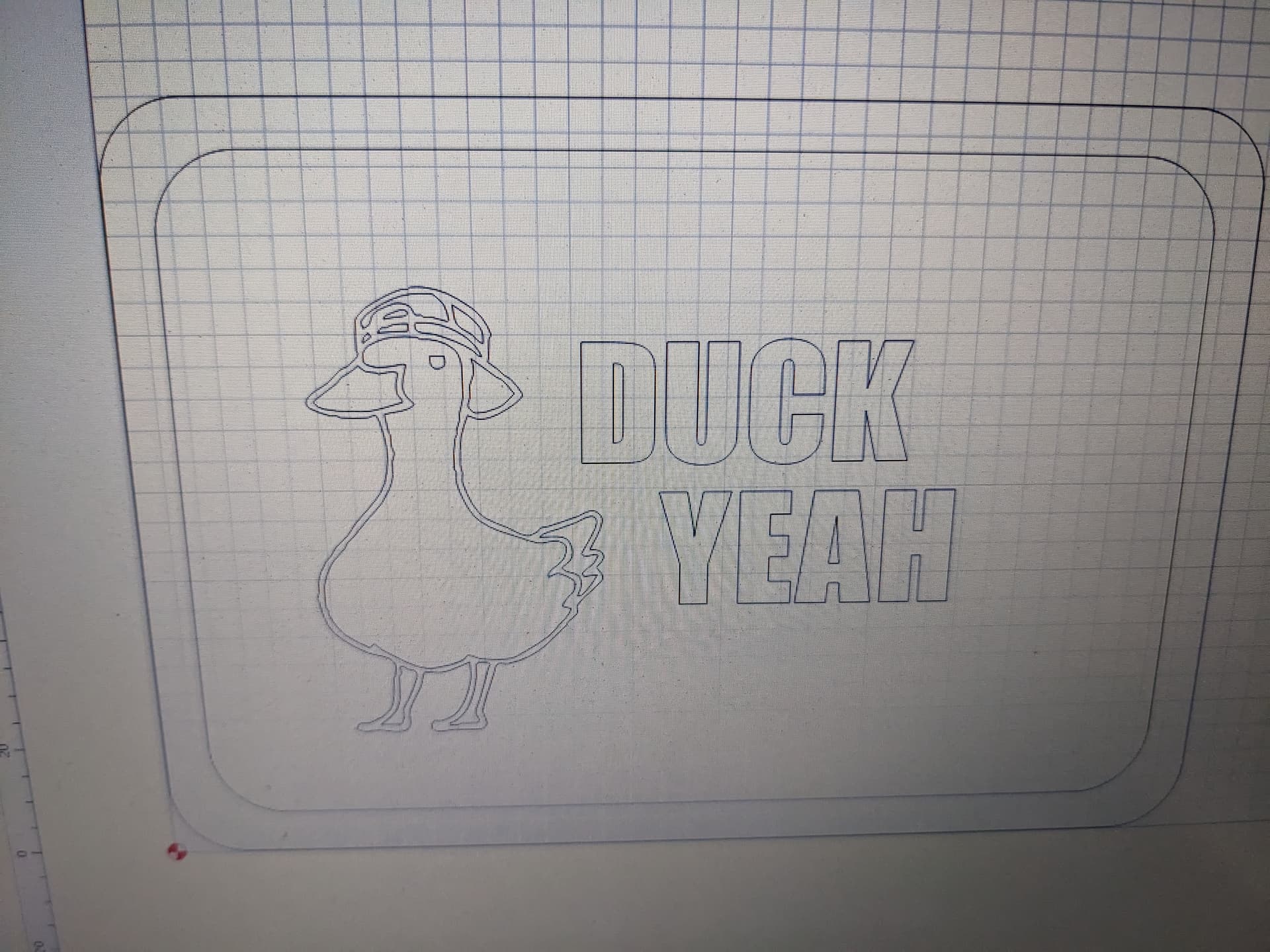
I’m going to be doing things in multiple parts. First is to make the tray and then the inlay plug.
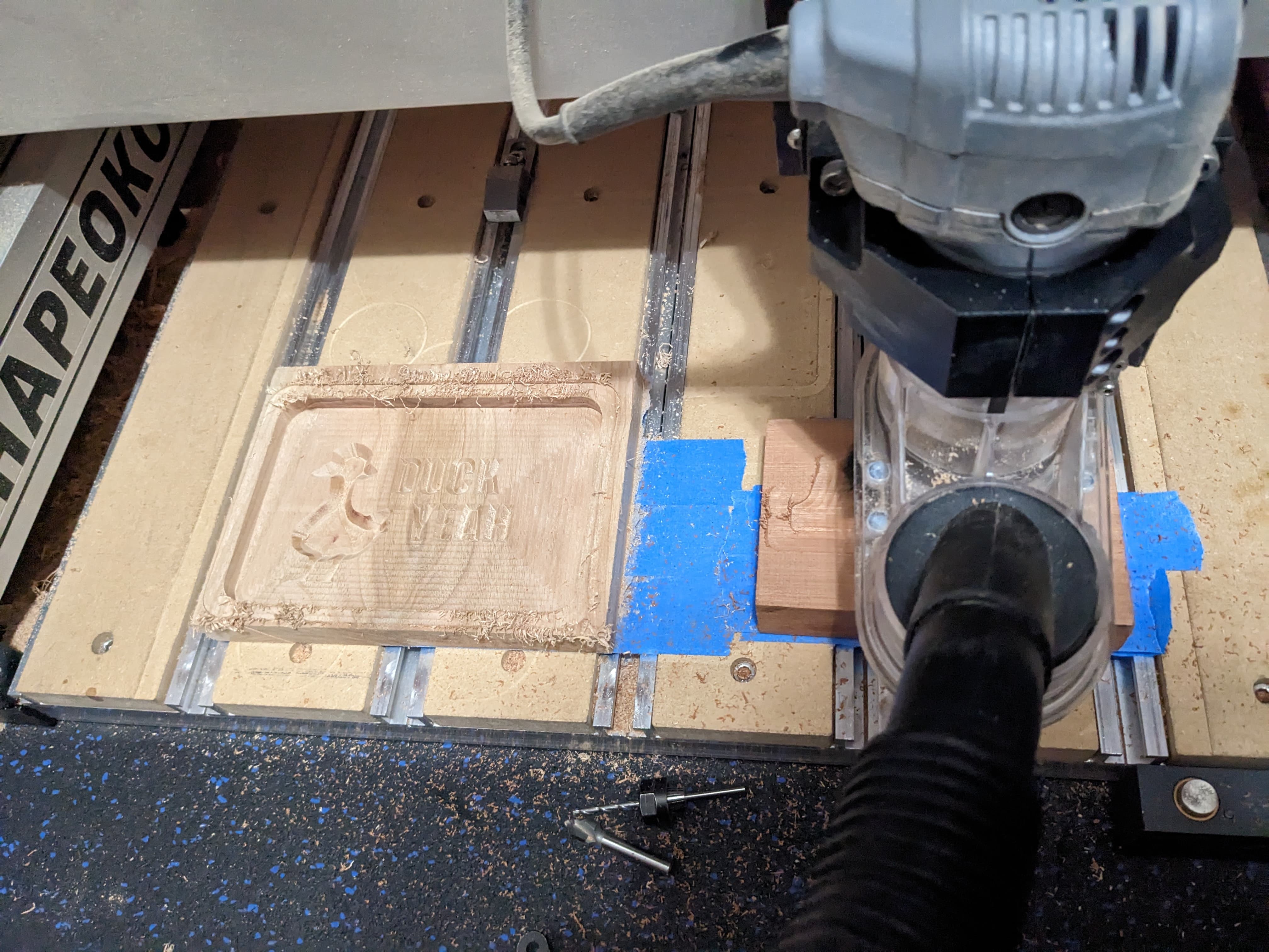
Inlay plug done.
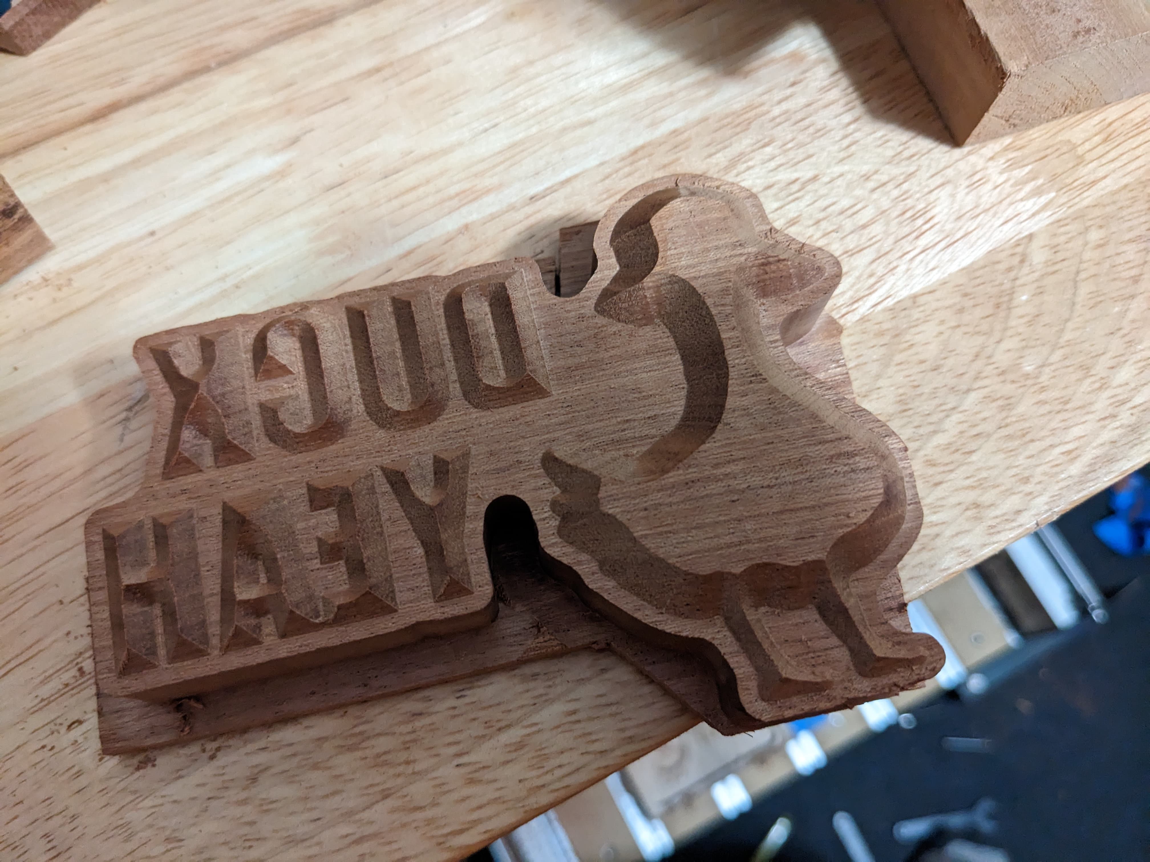
I should have done these in two separate parts. There’s a portion of the k that is raised that I didn’t notice until after glue was on.
We’ll see how it looks tomorrow. Worst case I could recarve the words out.
Up next is maple for the body and we’ll need to figure out what to do for the hat.
I think I have some yellow heart laying around for the beak.
Edit: I did a .5mm gap, so we’ll see how that looks tomorrow.
4 Likes
If you’ve ever watched videos of how folks do inlays in Vectric, ignore them. They’re jumping through a lot of hoops with the start depths and preoffsetting lines to make it work correctly. (Which is what we’re trying to avoid)
For what it’s worth, the “Bottom Gap” setting actually grows the inlay slightly to make sure you get as minimal a gap as possible.
The main reason to adjust the start depth for the inlay plug would be to leave only a minimal skin to remove after glue-up.
4 Likes
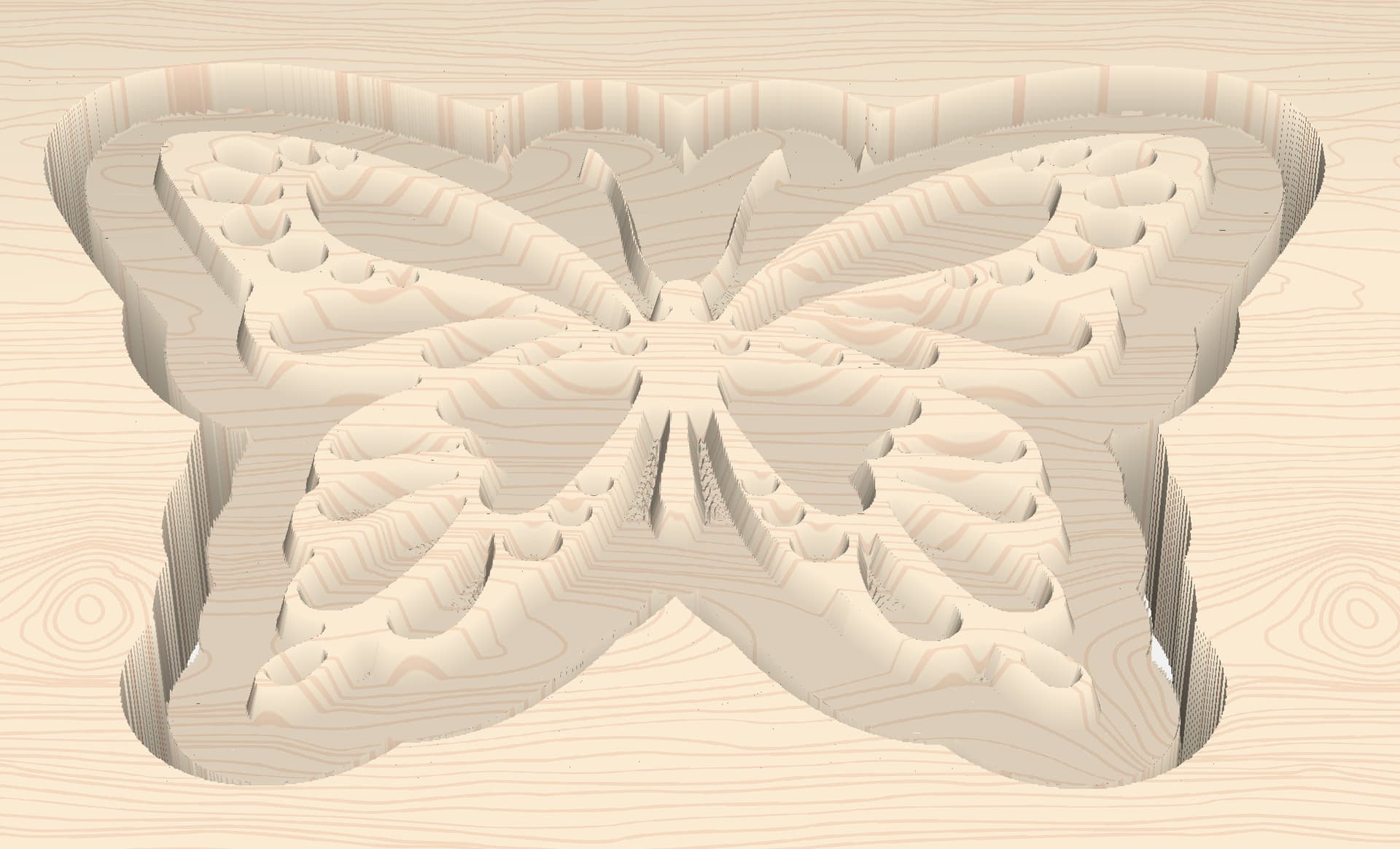
Just want to share a workflow tip I use:
For irregular shaped inlays (ie: cursive lettering, symbols, objects, etc) I’ve been using a 1/4" outside offset to define the advanced vcarve pocket boundary for the inlay. (re: butterfly outline in the attached image)
Then, I also add a contour tool path (outside/right, with a max depth of “t”) to that 1/4" outside overlay tool path with tabs so I can just have the machine cut the inlay out for me.
Since I typically use thin stock, it really doesn’t add much time, plus it saves me from having to use the bandsaw.

5 Likes

While waiting for inlay feedback, we made some changes for STL imports in CC Pro at:
What does this have to do with Inlays? Nothing, this is my way to bump the topic back up to try and get more inlay feedback.
5 Likes
Sorry…not feedback - I have no time to play this week
Just wondering: In Will’s example, the positive image is the male image, in George’s the male is the negative image. Is there any advantage to this or better results?
If you ignore the outside piece (outside the tabs), George’s part is ‘positive’ (embossed rather than engraved).
1 Like
I’d love to try the new inlay feature, but the C3D Repair team has my spindle controller, waiting for a board to come in.
Overnight a spindle controller to me and I’ll give the new feature a test drive.
Sorry…I meant Josh’s Duck
You can’t use the router?
That’s a good question. I think for me it made sense to do a negative for the duck and words. Especially for the duck since I was going to do multiple colors, but clearly I’ll need to do another with maybe an oval around the duck/words and have the base wood be the duck body and words. Probably will be able to test this weekend.
Overall though I think different images will have different approaches.
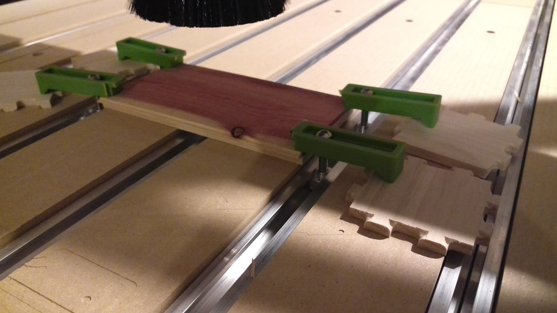
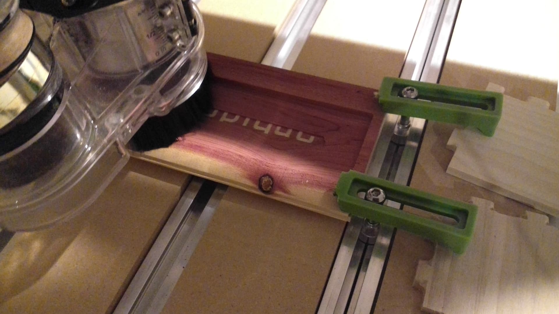
Lastly, the two pieces are glued together and then clamped.
Then, we make a file to remove the waste from the inlay portion (the traditional way to do this would be to use a bandsaw or planer)
inlay example — 4.5mm centered pocket bottom to remove.c2d (44 KB)
29 minute estimate in Carbide Create
also a 29 minute estimate in Carbide Motion, starting at 8:46PM
1 Like
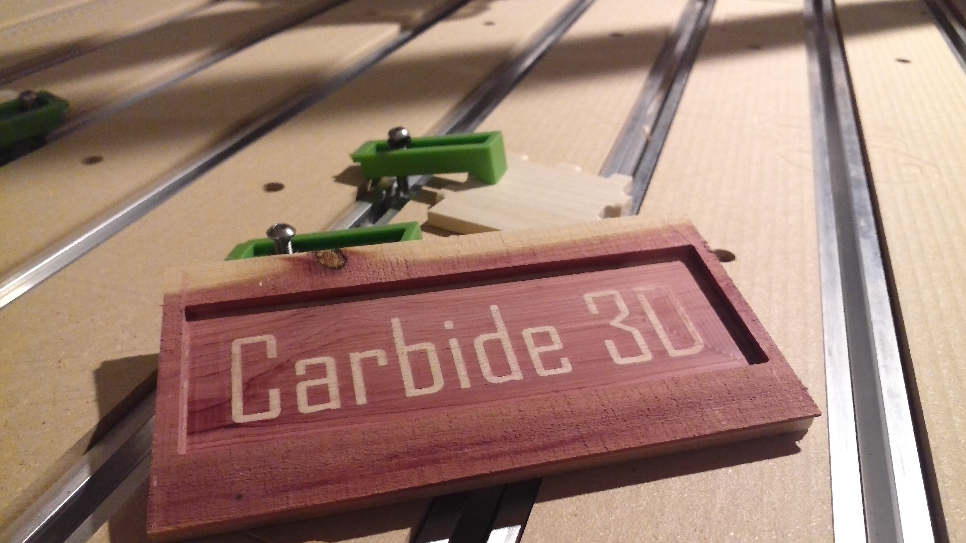
And w/ a bit of post-processing and sanding we arrive at a piece of cedar inlaid into a poplar board:

16 Likes
I guess it will depend on which wood you’ll want to cut away to reveal the writing. For example, if you wanted an inlay on the top of a box in a different color than the box, then the inlay piece would have to be reversed…otherwise, you need to cut away the box itself to reveal the inlay…You want to cut away the inlay to reveal the box…am I thinking straight?
It’s a function of “figure-ground reversal” — I probably should have put a border around my design, rather than a box to make the inlay element clearer.
1 Like
Rob,
FYI: I just want to share this with you.
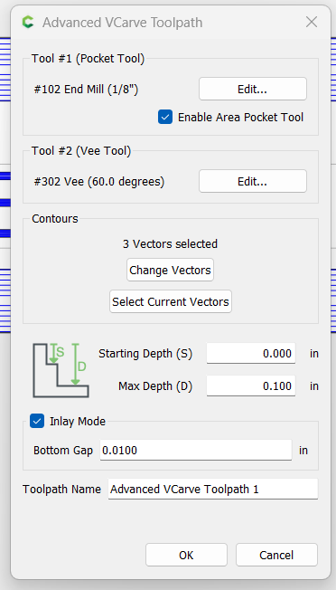
Since I can’t “test drive” the new feature until C3D repairs my spindle controller, I thought I’d install the CC 751-beta to create a side-by-side “manual vs. bottom gap enabled” comparison using my butterfly inlay file.
My manual method shows a 6 minute tool path time while enabling the new “Bottom Gap” feature results in a 24 minute cut time.
However, to be fair (“apples to apples”), both cut times are identical when I set the manual method to also start cutting at 0.00". Nice work, Rob!
I can’t wait to get my spindle controller back so I can try this out for real!
Tourist info:
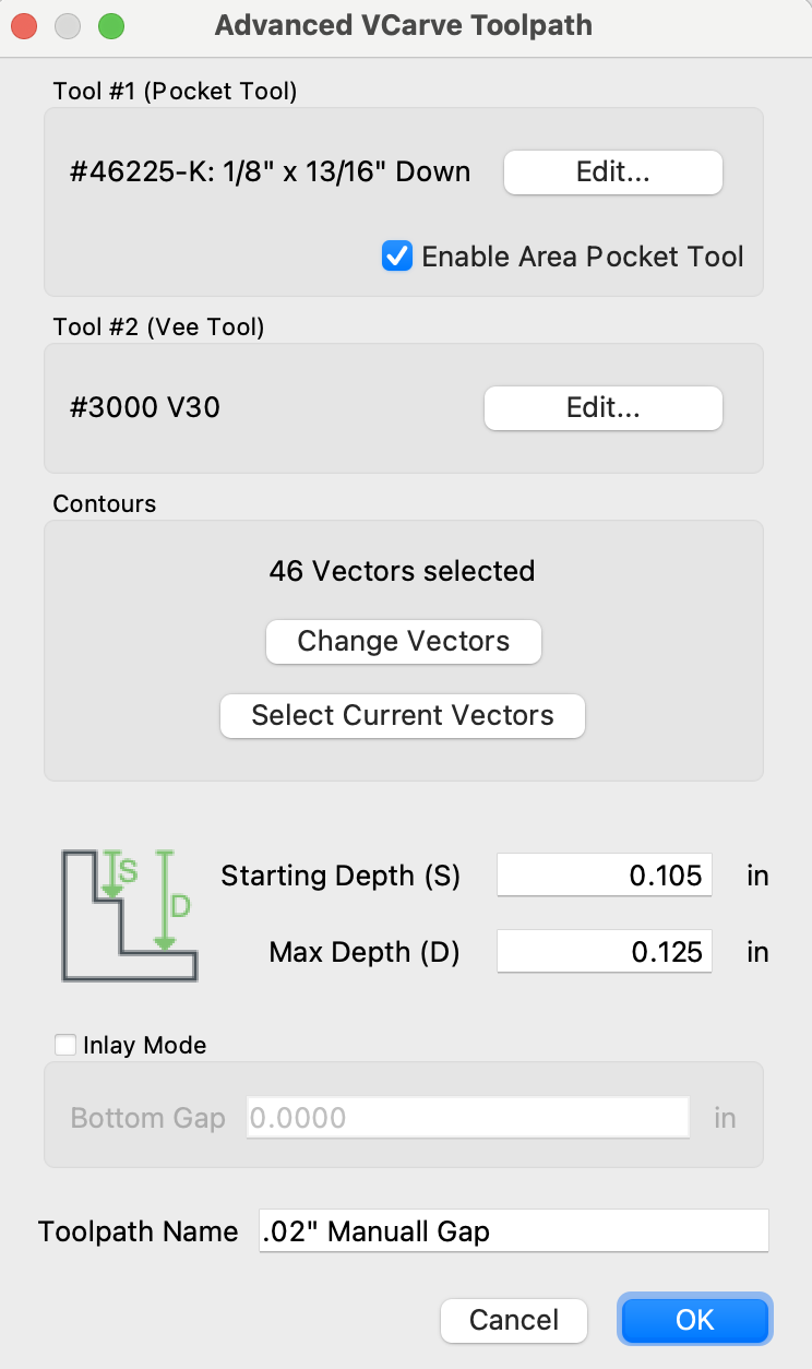
Manual Inlay settings:
Start depth: 0.105"
Max Depth: 0.125
Inlay Mode: n/a - not enabled
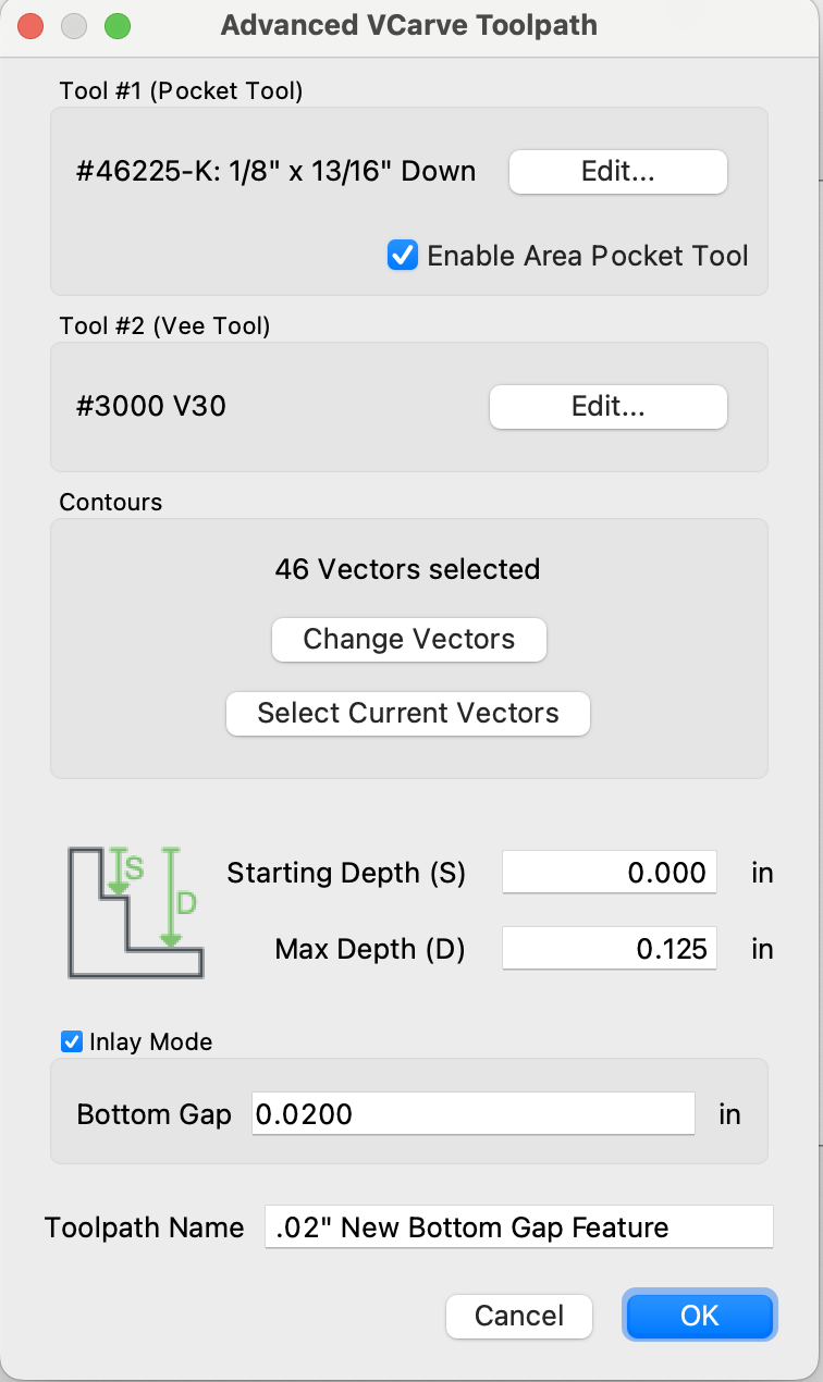
New “Bottom Gap” Inlay Mode Settings:
Start depth: 0.000"
Max Depth: 0.125
Inlay Mode: .0200"
I’ve added a few screen scrapes for your “reading pleasure” ![]()