Can you share a screenshot of what you’re seeing?
1 Like
MAC display 1280 x 800 and PC 1360 x 768
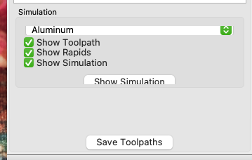
Neither of which meet our min. system requirement of:
- Screen Display: 1280 x 1024
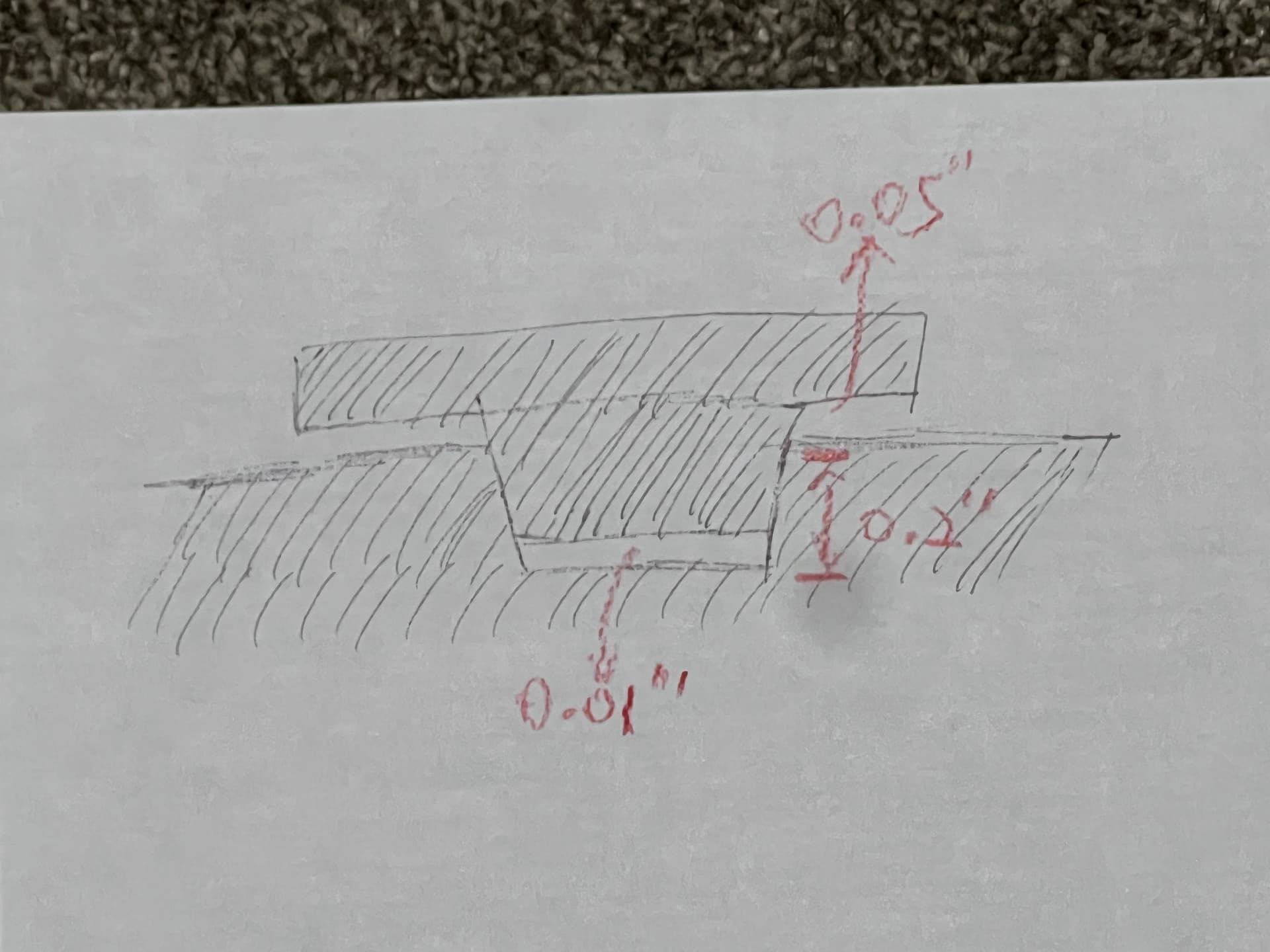
Are these the right numbers for the setup above?
Female: Starting Depth 0, Max Depth 0.2
Male: Starting Depth 0, Max Depth 0.24, Bottom Gap 0.01
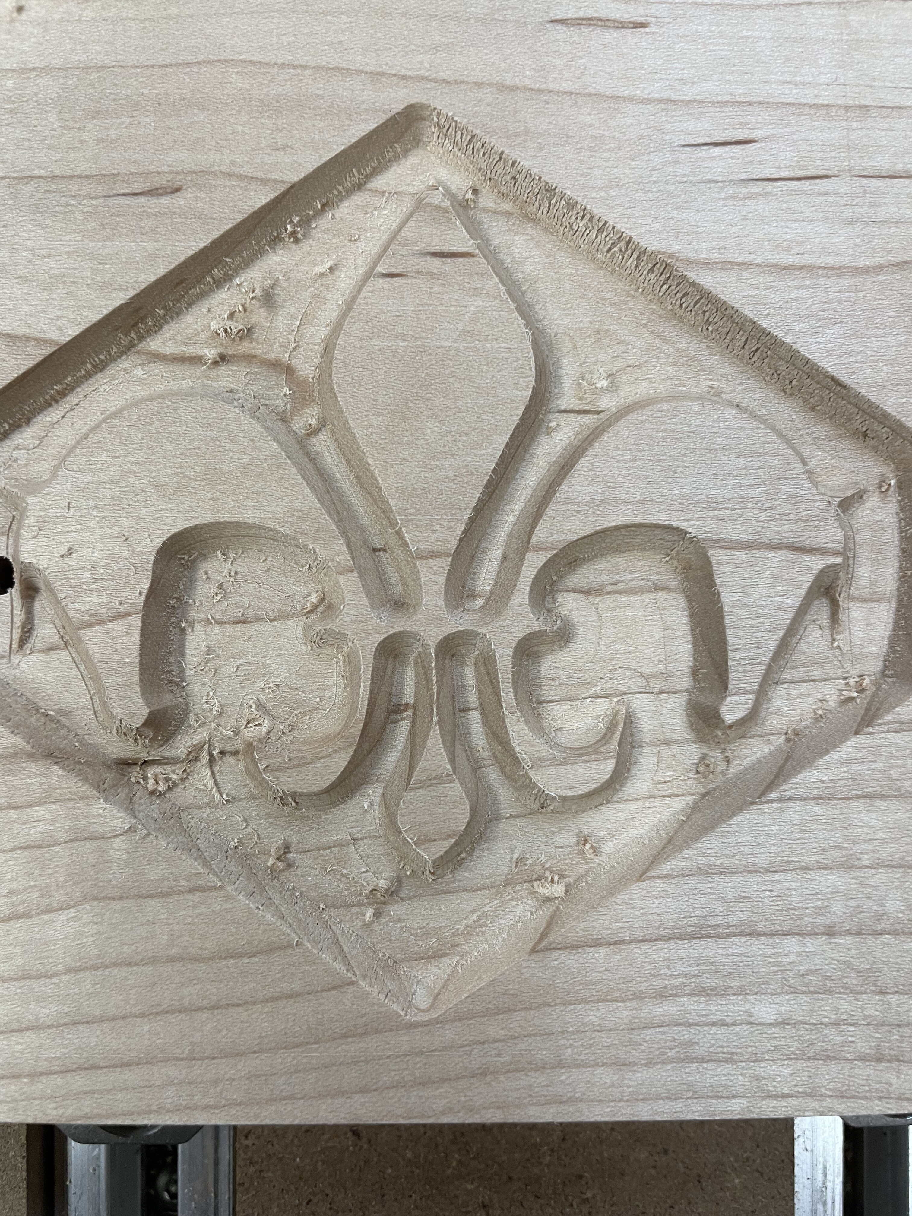
This is how it came out after cutting the plug . Still not sure why the plug was so loose. Any tips ?
that’s waay farther off than my machine achieved (and my machine has some evil mechanical issue where the X axis skips steps – still chasing down where that comes from)…
Are you sure the angle of your V bit is correct?
(do you have a way to measure that somehow)
Link to a youtube video on how to measure angles by cutting: Test your V-bits angle - CNCnutz Episode 151 - YouTube
3 Likes
Yeah I’m not sure why it happened, I’m going to try another test . The v angle is correct so it’s not a bit issue and the bit is brand new. Im thinking maybe something with the glue gap depth
I’m no expert, but I’ve found that the max depth for both the male and female components should be the same.
For what its worth:
My favorite settings are:
v30 bit
male and female max depths both = .125"
CC’s “Inlay Mode - Bottom Gap” = .02"
Disclaimer:
The views of this contributor don’t necessarily reflect the views of C3D employees, staff, friends, family, neighbors, or strangers. ![]()
Translation:
Your mileage may vary.
3 Likes
Is anyone having success with new inlay mode? I have been trying just basic square inlays and the plug is always too loose. I tried with both 30 & 60 degree V Bits. Should the values of the inlay and the values of the plug be completely equal?
Start Depth: 0.00
Max Depth: 0.2
Bottom Gap: 0.01
Yes, the values should all match up — at least that’s what worked for me for the Carbide 3D and “A” files above.
If you have files which aren’t working using Carbide 3D tooling, please send them in to support@carbide3d.com and we will try to look into them with you.
A similar situation happened to me, but for a different operation.
After several “try-this-try-that” sessions (ie: tramming, installing and surfacing a new waste board, using brand new end mills, etc), the bottom line, >>>for my situation<<<, was that after 9 months of casual use, the C3D router bearing had worn down enough to introduce a 0.030" runout. Thus every tool pathing operation I made was actually off by that much.
I’m not saying that this is your issue, but do suggest seeing if your router’s bearing is worn. e.g: put a long end mill in the router, tighten it as if you’re gong to make a cut, then apply pressure on the end of the bit to see if the shaft/collet assembly shows any (“wiggle”) movement.
For me, I cut several controlled “test pockets” (squares and circles) with specific dimensions (for example, from 0.125" up to 3" in 1/8" increments) then using both a digital and analog caliper, compared the pocket results with the original dimensions in my C2D file.
BTW: A new router resolved my issue.
4 Likes
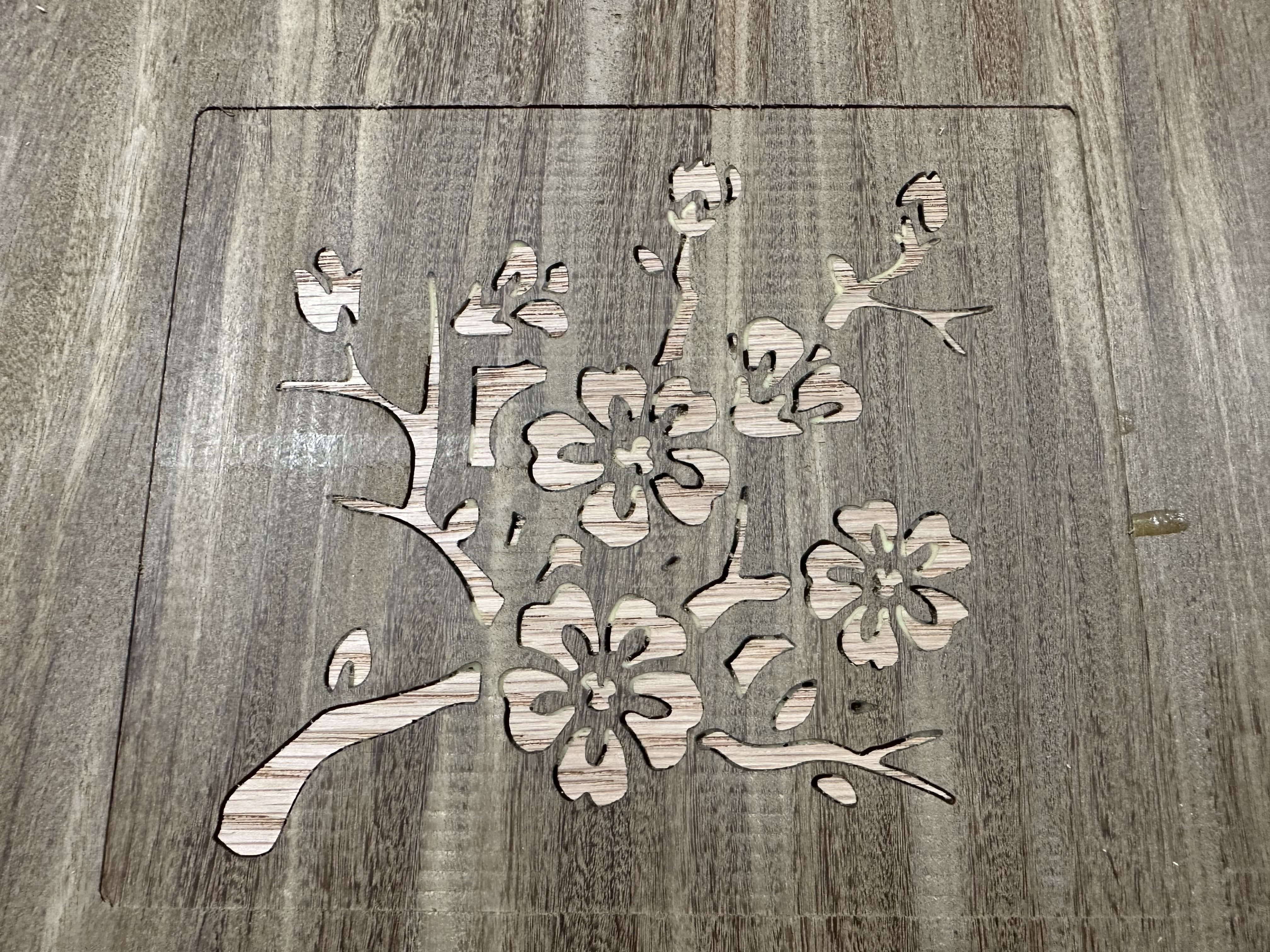
Someone mentioned that they were worried about small details going away due to the pocket expanding. I’m having an issue that might be something to do with that (or more likely just me making a mistake).
I’m using the beta inlay mode in 757. The attached file is the socket part of the inlay. As it is now with just the standard advanced V-carve it looks like it should. As soon as I click on inlay mode with a gap of 0.01 the pocket grows so big it obliterates the design. Hopefully is just me making a mistake instead of a bug. I think I am following the directions on the forum discussion of the beta feature, but I can’t figure out why it is doing this.
flower inlay-pocket.c2d (92 KB)
Thank you for any help you can provide.
1 Like
I thought the ‘Inlay mode’ was for the plug only?
1 Like
That was it. Thanks for reminding me. I had used it successfully before, but for some reason I got the order messed up on this one Thank you!
Dont know what to say. Either my s3 xxl is junk or the program. I have redid this inlay wedding present multiple times and spent probably 30 hrs on it. My machine will just not cut it worth a crap. Always gaps. I did each piece by itsself to see if it helped. Nope. I went and bought new clamps im clamping the male perfectly flat all the way into the female too. Most of the gaos had some glue in them but i can poke it right in. No wood under it. All peices male and female were brushed perfectly with glue and brushes.

Looks like all the gaps are due to slop in the Y axis. With the machine on, but not running, can you move the tool front to back? (Might need an indicator to measure).
Given that everything seems to fit perfectly side to side, I doubt it’s a problem with programming.
Something mechanical on the machine not holding those Y dimensions.
Maybe try a roughing → finishing strategy to reduce forces that pull your Y axis out of line??
1 Like
The defects are also along the grain, and in one area (under the “B” in Bixler) around knots, so may be caused by failure of the wood, also the differences of climb vs. conventional cutting, so adjusting feeds and speeds may help, as will a more acute V endmill (which will leave less material/cut away more, but which will have less width variation for a given height variation and should be less likely to cut away excess stock).
Using a V tool which is specifically intended for wood cutting will help as well.
I ran into a similar problem with a walnut/maple combo. The finer maple details would get cut off and there were some small gaps. I even switched to a new 60 degree downcut bit. I also spent a lot of time on machine tuning but hadn’t thought about slop at the spindle.
I started to think maple wasn’t a good candidate even though it is pretty hard.
Mine fit together well. And the plug really looked OK, but delicate. I may have lost the detail bits in the post glueup flattening.
After lots more reading I am going to try checking for slop at the bit and maybe repeating the test in MDF to eliminate grain as an issue. I noticed yesterday that the bottom hole in my collet nut seems a little raggedy but not sure if that is an issue as long as the collet is gripping properly.

1 Like
Thinking about just fixing it with an s5 4x4
Hello Rob,
If i select the inlay mode and set the bottom gap to 1" on the piece that is reversed ( being inlayed) will I then have a 1" gap between my pieces after glue up? Does it cause the depth to be continued along the path of the 60degree angle of the cutter?