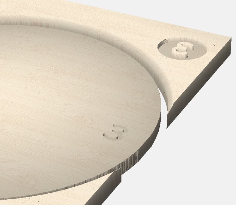
My thoughts were to do a wooden clock face, 12 inches in diameter, with a slight convex shape and to inlay alpha numeric digits using a contrasting wood. The stock thickness would be .750”. The rounded shape would be 10º with a height of .250 and a base of .500.
My thoughts are that I would need to do the inlay portion of the project first, on the flat surface, then apply the rounding model tool paths. But, I’m affair the rounding model tool paths will wipe out the inlays, especially near the edges.
Is there another way to go about this? Is it possible to do the inlay portion on a rounded face?
The main purpose of a clock is to tell the time. In the case of a retirement its main purpose is not to tell time but to just be wall art. My question would be why make it so complicated. Of course I understand the challenge and you can likely make it work but why? Other than the challenge what is the purpose of making a round dome shape?
I am sure you will get help with this but keep in mind the purpose and it is to tell time but to amuse people about the retirement. Since we are taught to tell time in school at an early age the clock will still represent the current time so just make sure the hands contrast against the background to the primary purpose of a clock is to be able to read it from across the room in dim light.
If you do an inlay on a rounded surface you will need to use a simple pocket to receive the inlay NOT anything with a vbit type of inlay process. I used a 1/8 em and then 1.5mm to get the finer edges. When you create inlay (male) you may need to offset the pieces by .01 in smaller so you don’t have to fight tapping it in. After that then do the convex toolpaths. Hope that makes sense.
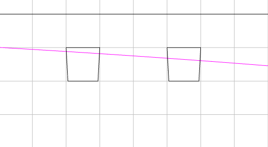
I don’t see why you couldn’t use a v-carve inlay. You just have to account for the curvature & the height at the finished surface of the model. I would use a very steep (6°) V-bit
The difference in height across the number is less than 1/16"
Thank-you @Tod1d. I was thinking a steep v bit was the answer but for the life of me I could not figure out the radius of the top arc. That’s was the missing link to draw this up in a profile view to see if the carve would come together and not wipe out the inlay.
I frequently draw up a side/section view to work things out. You might have to get creative with the v-carve depths to get a match. I tried to match mine up from -0.125 to -0.250, and ran the female 0.1875 deep (from the -0.125, so 0.3125 total), so there’s a good 0.125 + of stock to glue.