Hello all, after many videos I find that I may be confusing myself here and would like to ask someone to verify my settings for me please.
Carbide Create Build 778 Built on 2024-07-29
2 Squares Rounded corners, nothing fancy just practicing before ruining a good piece of expensive stock.
Stock = 0.99
Offset = 0.50 to the Outside
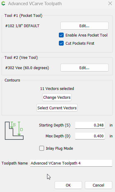
Tool Paths = Advanced V-Carve
Entire Box and Offset selected and highlighted
1/8’ roughing bit
60 Degree Vbit
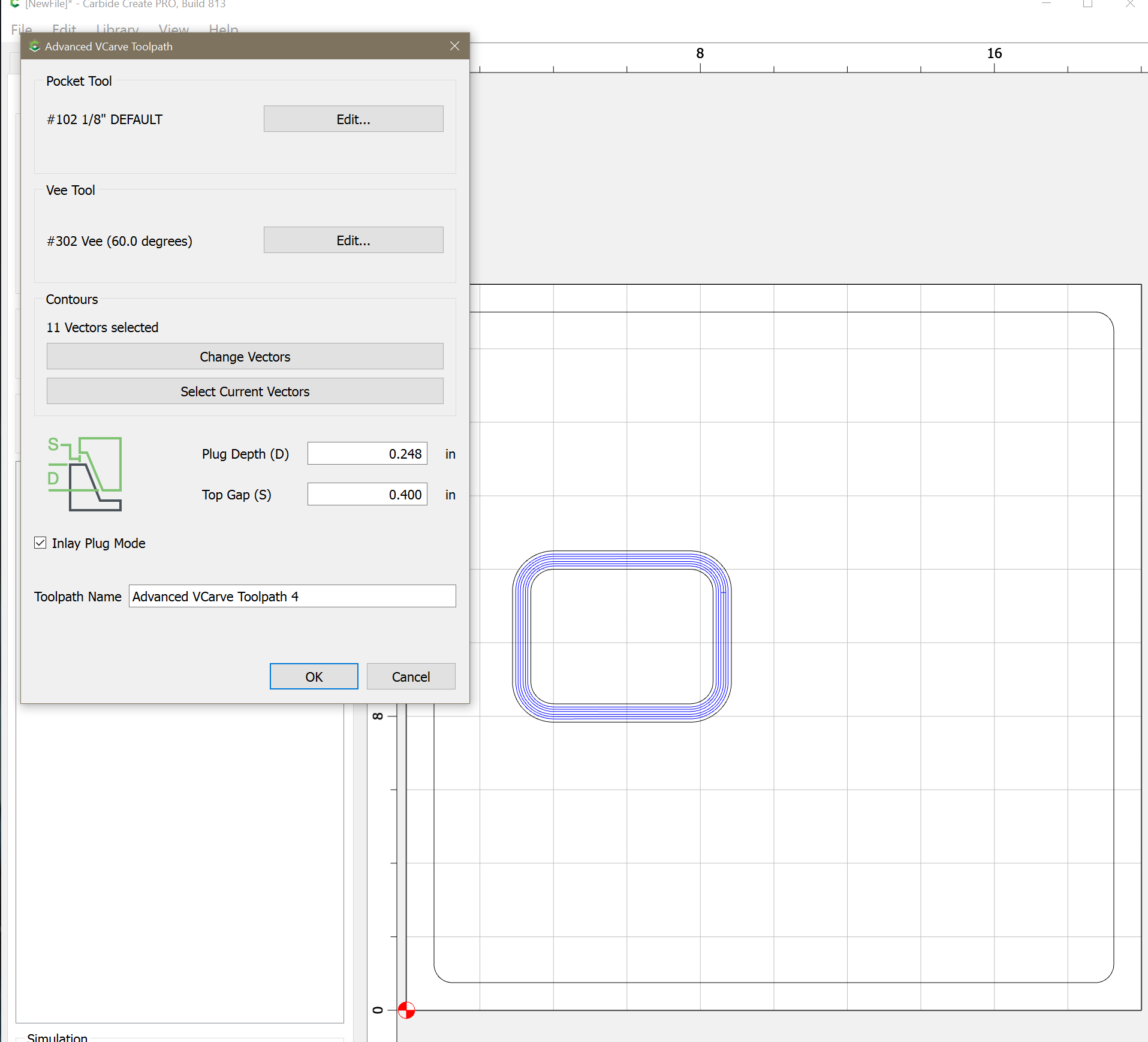
Inlay Plug box checked
Depth = 0.250 - .02 = (0.248) My project is 0.250 deep but I subtracted .02 for glue.
Top Cap = .04 Seems to be the standard from what I have read.
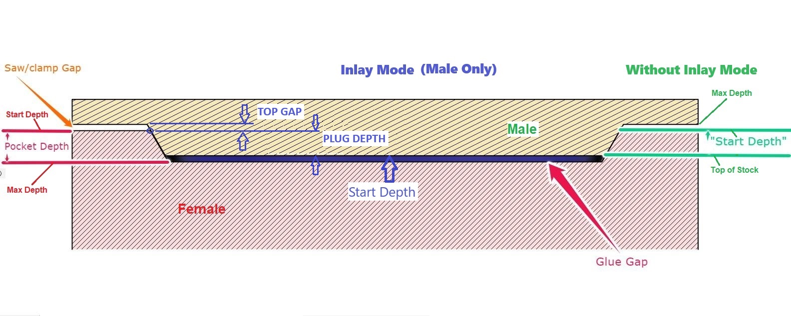
4 attempts and im ready to throw something across the shop, either the cut is off, not deep enough or too deep. If I understood correctly top gap if for the glue squeeze out correct? The Male and Female plug should mate like a puzzly right? Or should the plug be proud of the pocket?
Hi,
I looked at your file.
Could you please clarify your design intent? I see a channel with V-walls cut out outside the rectangle when I run a sim. Is this what you were aiming for? I don’t see inlay plug mode checked.
I don’t see any toolpaths for the plug.
I typically start at the surface (0) and would go max depth 0.250".
And take .020 off the plug. If the female is 0.248 and the plug is 0.250, there will be no glue gap.
The plug should be proud of the pocket.
BTW, were all 4 attempts with the same tool and same file? If so, could the tool bit be getting pulled out of the collet?
The file you shared does not have Inlay Plug Mode checked.
Start depth 0.248 Max Depth 0.400 means the top gap is 0.152 ??
Your math above, Depth = 0.250 - .02 = (0.230)
Top gap is a “saw gap” so you can turn it sideways & bandsaw the base off the male inlay.
Or just so the base doesn’t contact the female side & allows the male to fully seat in the pocket.
Glue Gap is the female max depth - male start depth. Or with the inlay mode, the female max depth - male plug depth.
thank your for your indepth explanation of saw gap, and pointing out the inlay plug mode was not checked along with my math is wrong… why is it so hard for someone to just help answer the question…
its a simple square for christ sake… I am a newbie yes, inlay is kicking my A**… so are people that just can’t say ok here is what you need to do…
may as well find another support group to get help with this matter… thanks for your reply…
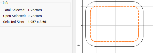
I have a square cut into a practice piece of wood,
I want to cut a plug (inlay) to fill the hole back up (as if it never happened)
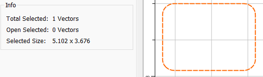
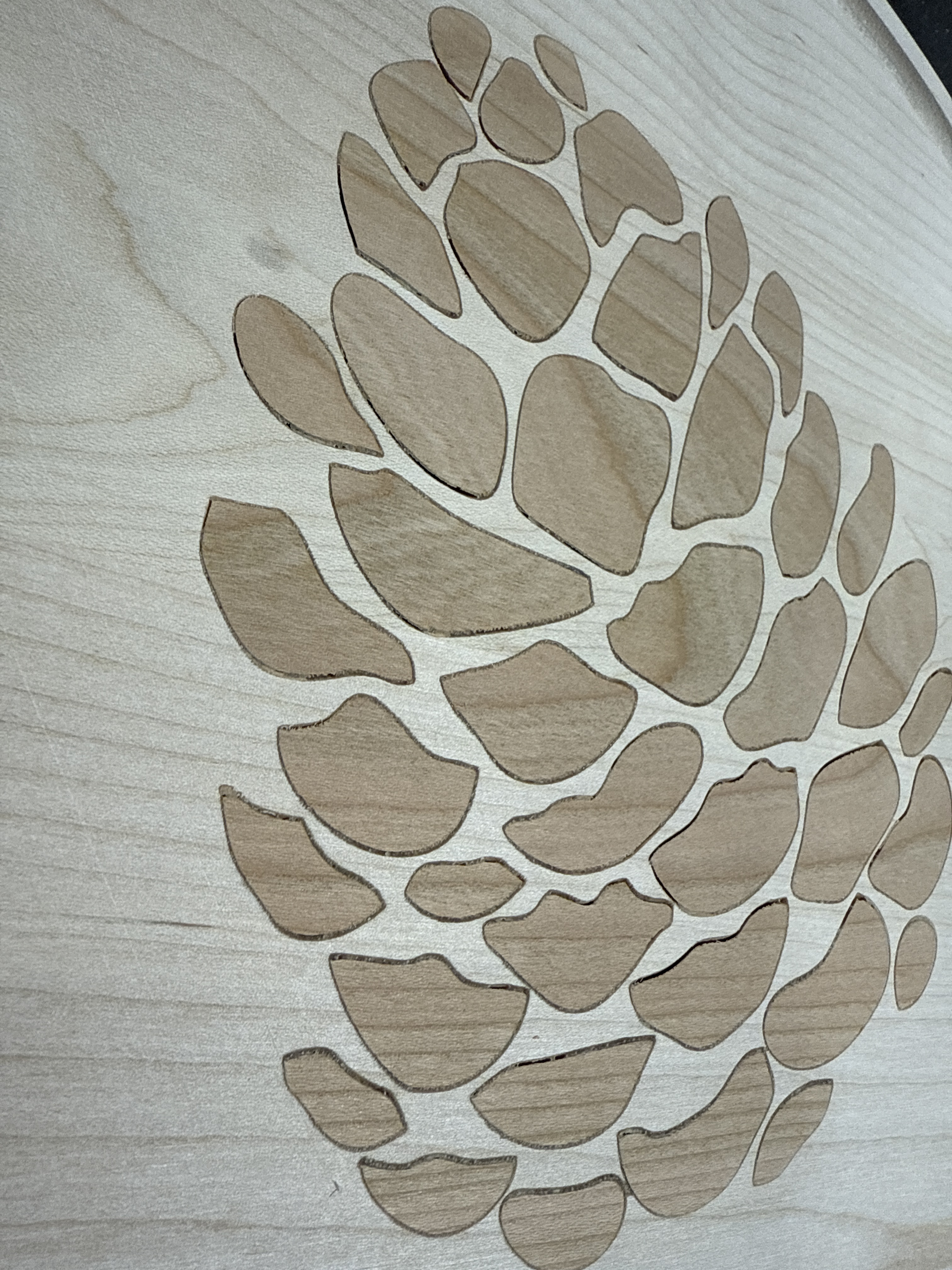
depth is 0.250 Female the photo is not the square, the photo is of the plug.
Should I put a (offset) around the square, then select both the square and offset and use the advanced vcarve option in carbide create v7 build 777. ( see attached)
Do I even need the Offset vector ?
every attempt the distance from the bottom of the plug to the bottom of the FM is way too much, what am I doing wrong…
I suppose its too difficult to just get someone to say ok here is what you need to do… but its ok, yall go ahead and be critics if you wish, I will not let your arrogance stop me from learning.
Create your offset or another vector around the male shape so you can fit the female to the male without removing the male from the machine.
Set the Plug Depth to 0.130", set the Top Gap to 0.120" or greater. Cut the male.
Now fit the female to the male & measure the top gap. It should be 0.120", but it will likely be a little bit off. This could be due to accuracy of the machine, slop or deflection, or a Vee bit without a perfectly sharp point. Either way, adjust the plug depth to get to the actual 0.020" glue gap you want.
Most folks use a matched pair, one for the negative, one for the positive — the latter will usually have some offset geometry to separate it from the surrounding stock and make it easier to apply.
Did you look through:
and compare your file(s) to the ones in that thread?
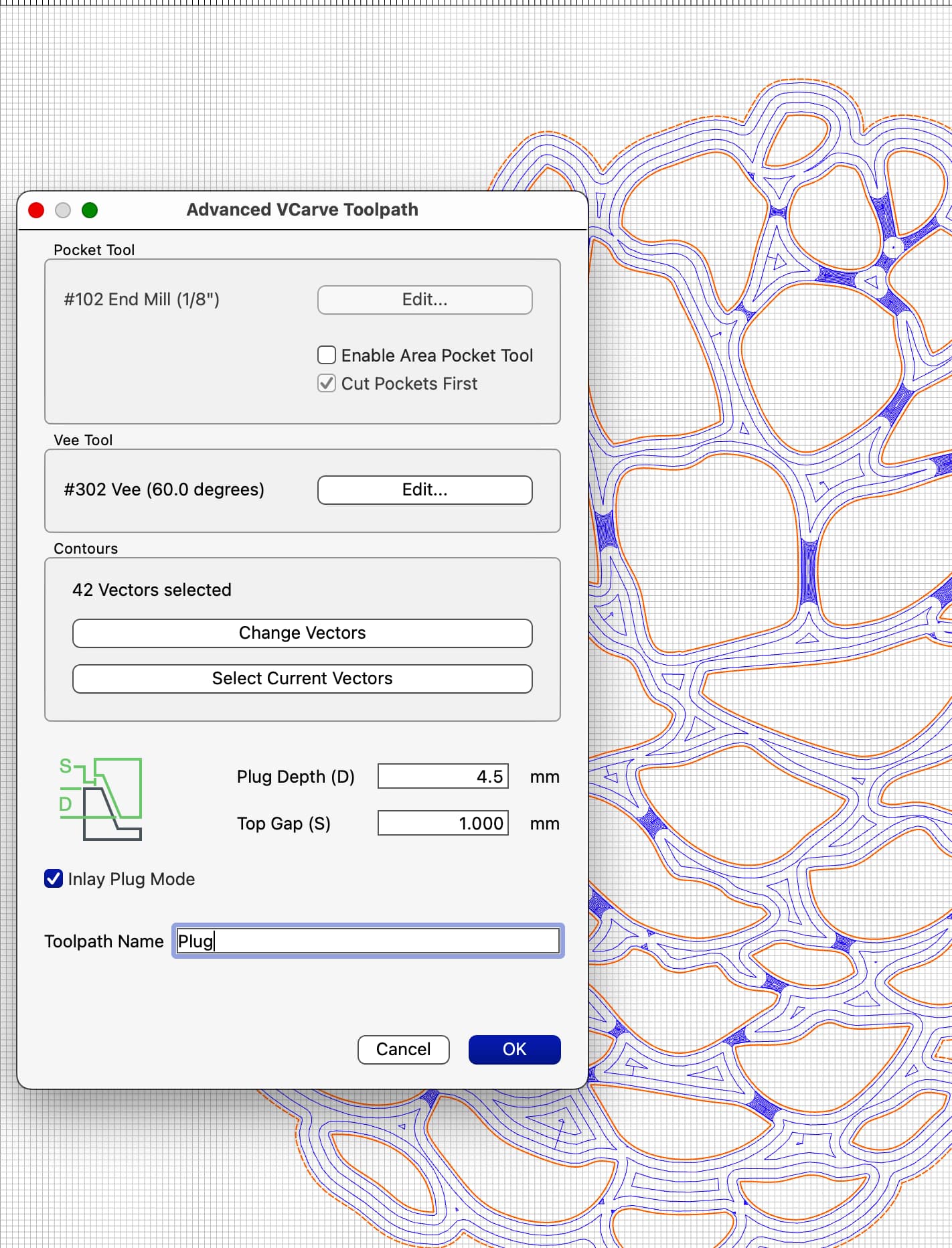
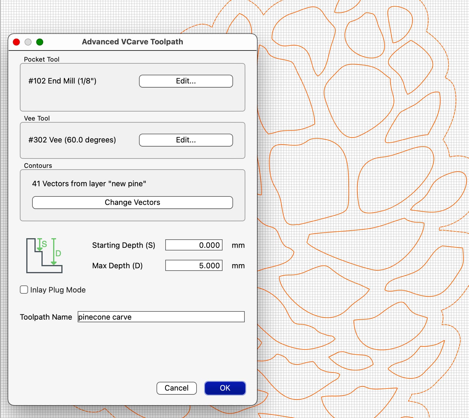
Q: with v8 how to define S and D with inlay mode? Still 1mm/S - 5mm/D and then when making inlay 0.5mm? Had success with your video but now settings changed and I didn’t get the same result.
This is with new settings in CCPro V8. May have been human error when clamping(?) but a small check of file would be appreciated before I cut a new one