I’ve watched a bunch of vides on the subject. Would someone mind taking a look at what I did?
INLAY-TEST.c2d (772 KB)
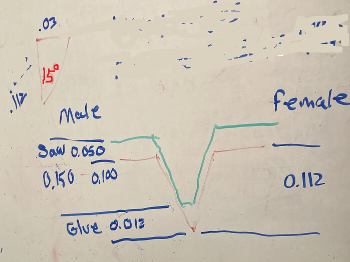
Your pocket, the female side, the lines are about 0.060" apart. With a 30° Vee that means about 0.112" deep. You want the male to fit into the female about 0.100, which is controlled by the Starting Depth. So that looks good. The difference (Max Depth: 0.150) is how far the rest of the male plug will sit above the female, or the “bandsaw gap”. So yours should be about 0.050". This should work
The only thing I would change is the depth per cut on the tools. Depending on the material.
Both 1/16 mill & 30° are delicate tools, I wouldn’t go more than 0.050". 0.030 if cutting hardwood.
1 Like
I’ll make the adjustments. Thanks for looking.
I’ve switch back to V6. Here is the new C2D file with the adjustments made. And here is the G-CODE. For some reason it goes right to the max depth of 0.150". No I didn’t check it before hand and yes I broke the 1/16" bit. But that’s on me, I should have known better. Any Idea why it goes to max depth?
Ugh! The Plug is because the start depth is 0.100. Create 3 plug operations, from 0 - 0.05, then 0.05 - 0.100, then 0.100 - 0.150.
It looks like the pocket (female) is doing the same thing. With DOC on the tool at 0.050, and max depth of 0.150, it should be cutting 3 levels. I’m sure I’ve had V-Carves that cut multiple depths, so not sure what’s going on with that. Might need an extra path for the pocket as well.
I’ll do that. But why wouldn’t it use the depth per pass setup from the tool definition? Doesn’t that kind of defeat the purpose of putting in a depth per pass if it’s just going to go to the max depth in the 1st pass.
If I make 3 plug operations at different depths, does that mean I’ll have to switch tools for every depth?
Thanks again.
Because the starting depth is at 0.100, it thinks you’ve already cut down to 0.100, and only need to remove the remaining 0.050. But it also puts the vector at the starting depth, which is what you need to make the plug fit into the pocket. It’s a limitation of the software that you have to work around.
Sadly, yes. You will need to change back & forth from the end mill to the Vee cutter at each level. Unless you want to edit the G-Code and re-arrange the toolpaths so there’s only one toolchange.
Another possibility is to use a Pocket toolpath (that does use depth of cut) to clear out most of the material first. If you program a pocket toolpath with a 0.090" tool, then use the 1/16" tool in the machine, that will leave the offset clearance for your vee bit. You could go at 0.030 DOC to 0.120 max.
2 Likes
For what it’s worth, here is the formula I use for V carve inlay work.
Considerations:
- I design in VCarve Pro. I assume there is a way to do this with Carbide Create but I’m not familiar with it.
- I use a 1/8 inch end mill for the clearance toolpath and a 15 deg V-bit for the V carve. The sharp angle of the V-bit allows for deep penetration while giving reasonable detail at the surface.
- As you can see, I work in the metric system. I’ll leave the conversion up to you.
When making the male cut you need to create three tool paths in order to remain within the cutting limits of the end mill.
Path 1: Start depth 0.5 mm; Flat depth 3 mm.
Path 2: Start depth 4 mm; Flat depth 3 mm.
Path 3: Start depth 7 mm; Flat depth 3 mm.
This will create three tool paths for each of the two bits. Total amount of material removed will be 10 mm.
Run all the end mill tool paths first, then run the V-bit tool paths. You don’t need to swap bits for each path. End mill first, then V-bit. Personally I disregard the Path 1 and 2 created for the V-bit and just run Path 3. The V-bit will handle the depth just fine since the
endmill has cleared away most of the material.
Making the female cut is much simpler. One toolpath for each bit is all that is needed. Just make sure you use the same two bits that you used to make the male.
Start depth 0 mm; Flat depth 8 mm.
The male should now fit into the female cut leaving a 2 mm bandsaw gap.
Hope this helps.
1 Like
Hey @cnc_aero I did a detailed write up here with diagrams explaining each cut. This was using Estlcam, but same thing can be done in CC.
Hope that helps.
1 Like
Thanks to everyone with the help and advice tips. I made a separate pocketing cycle and went down to my desired depth of 0.150” and it worked perfectly. Then when the v-bit went to work it destroyed the walls that were remaining. I’m sure it’s just because of the geometry I’m trying to cut. They are very thin by the time the pocketing is finished. I’d have to make it larger or redo the v carve portions so that it doesn’t try and take it all in one pass. After that happened I took a step back to figured things out. I haven’t been back at it yet.
I will try it again with all the new knowledge I have from everyone here.
Thanks to everyone again and I’ll post the results soon.
Cheers
Yeah - that’s why I run that as a two pass for both the pocket and the slug to get to full depth. Material also matters, some are really brittle and prone to chipping out or two soft and tear out instead of cutting. A good test is to use MDF or some variant - because there’s no grain it cuts really nice and smooth. Get that working and you know your formulas are right to replicate onto your actual pieces.
I take a simpler approach: set z 0 height to surface. Raise the bit by the amount it thinks it’s going to start and re-set z0 to that point. Run the paths. Move z0 back to surface. Set z 0 and run it again.
1 Like
This topic was automatically closed after 30 days. New replies are no longer allowed.