I’ve struggled with understanding how to do an inlay for about a year. Lots of resources explain how to do it with various paid programs. But none of them went through how to do it with free resources. I finally stumbled on a video in German that I was able to watch what he was doing and fully understand. It was so simple, I was a little mad. ![]() Once I understood what I needed to do, my very first inlay came out flawless. I’ve made a dozen in the last two weeks, including some mixed media (aluminum into wood, wood into aluminum).
Once I understood what I needed to do, my very first inlay came out flawless. I’ve made a dozen in the last two weeks, including some mixed media (aluminum into wood, wood into aluminum).
I’m capturing the steps here for anyone else trying to figure out how the heck to make this work with free software and not getting lost in 3D software like F360 or FreeCAD. Here’s what I used:
- Inkscape 1.2
- Estlcam 11.244
- cncjs 1.9.26
These steps would work using Carbide Create or other programs.
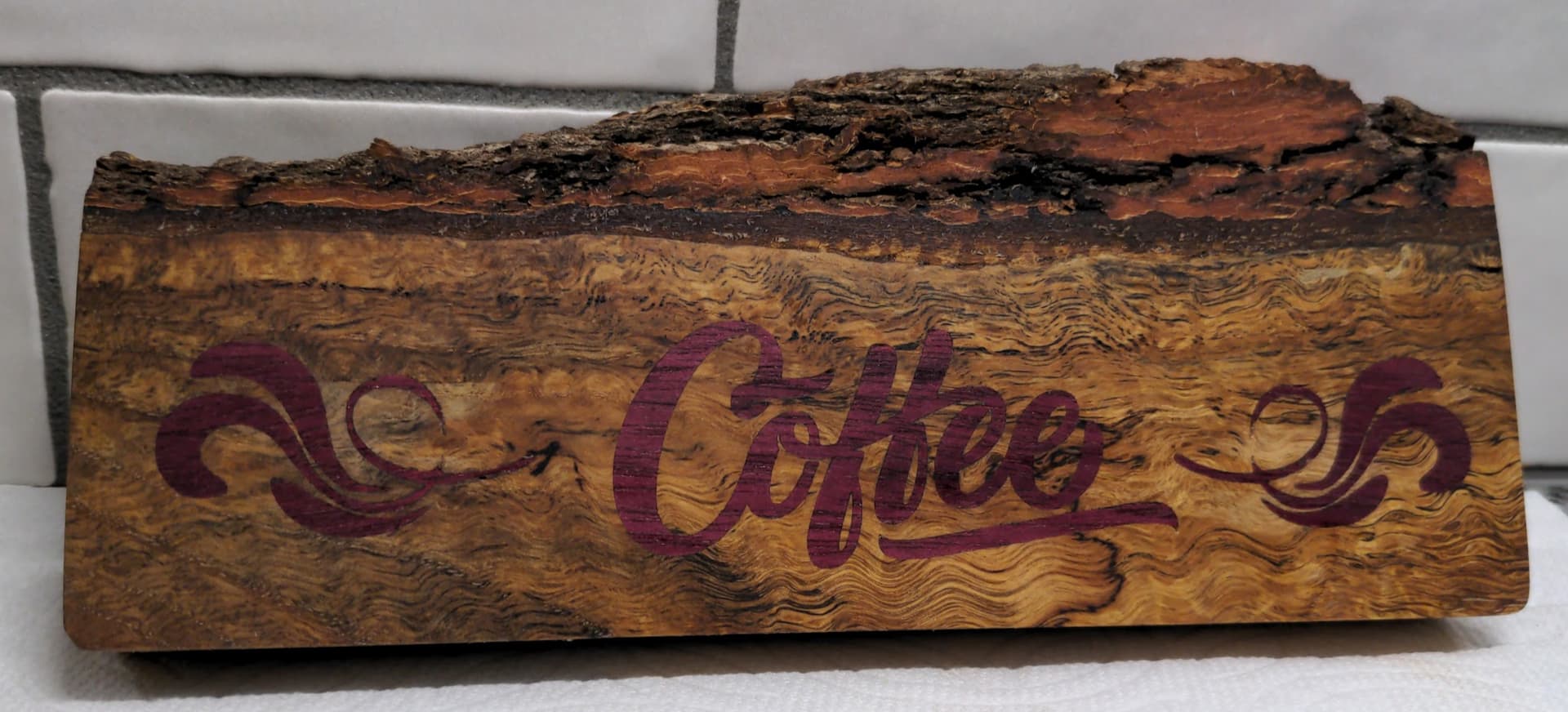
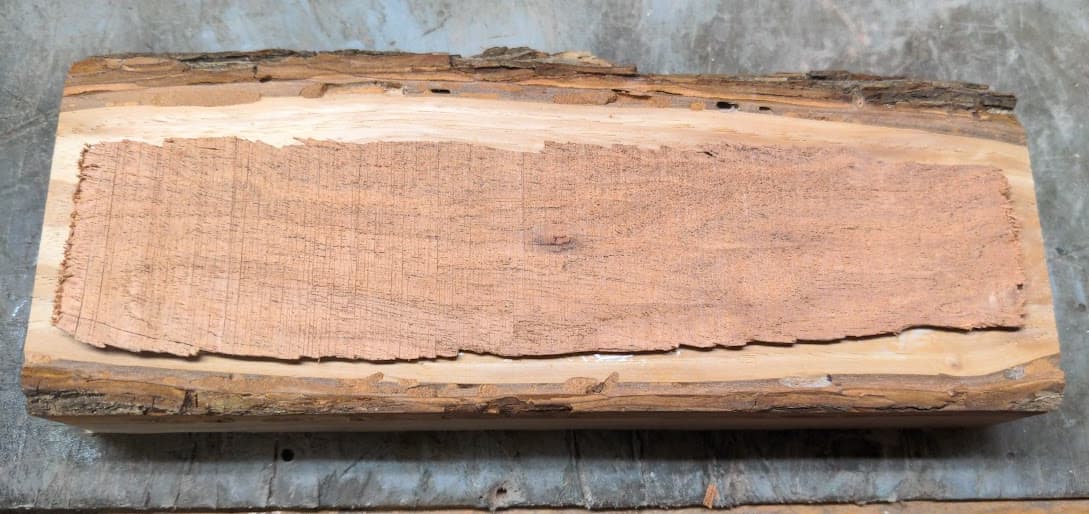
Here’s my very first inlay ever.

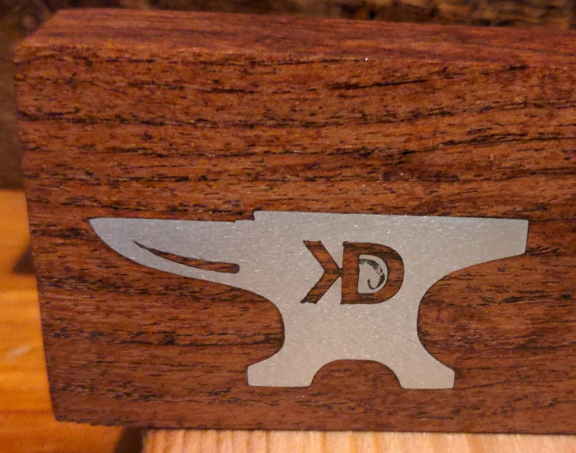
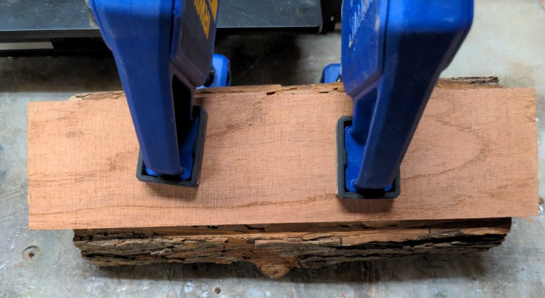
And here’s my second

So let’s get to it!
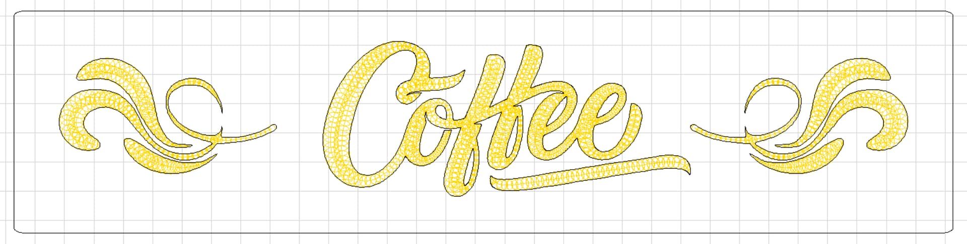
- In Inkscape, create the drawing for your project. This is you design that will be v-carved into your material.
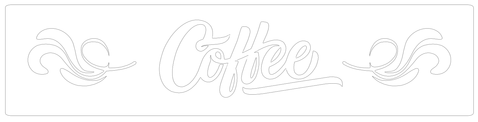
(tip: I like to work in outline mode: View > Display > Outline.)
(tip: Set your stroke width to 0.001mm. Why? CAM programs can interpret stroke width differently, this eliminates stroke width impacting your final cut. Object > Fill and Stroke > Stroke Style > Width.)
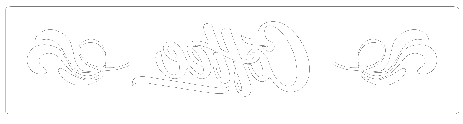
- Select your design, make a copy, and then while it is selected Object > Flip Horizontally. This is the design that will be inlayed into a your base. You should now have both designs, one right reading, the other reversed. Save this file as an svg, like Coffee Example.svg.
(tip: Before saving, select all then: Path > Object to Path. This ensures all your text and rounded corners will import properly.)
- Open Estlcam (or Carbide, etc.). Import this file File > Open > Coffee Example.svg

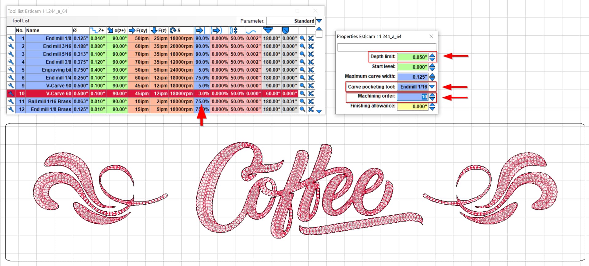
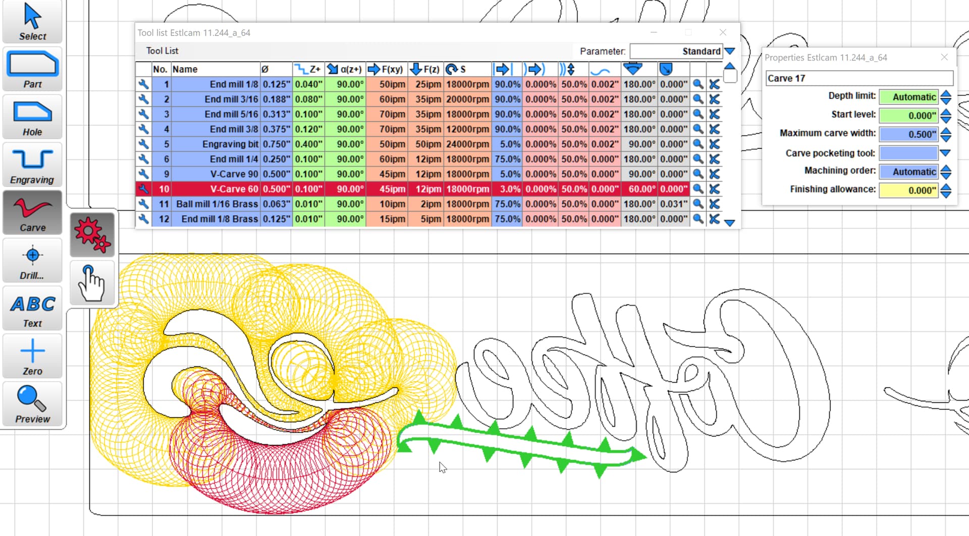
- We’re going to work with the top design first. Using the Estlcam “Carve” tool, select the inside of each piece of the design.
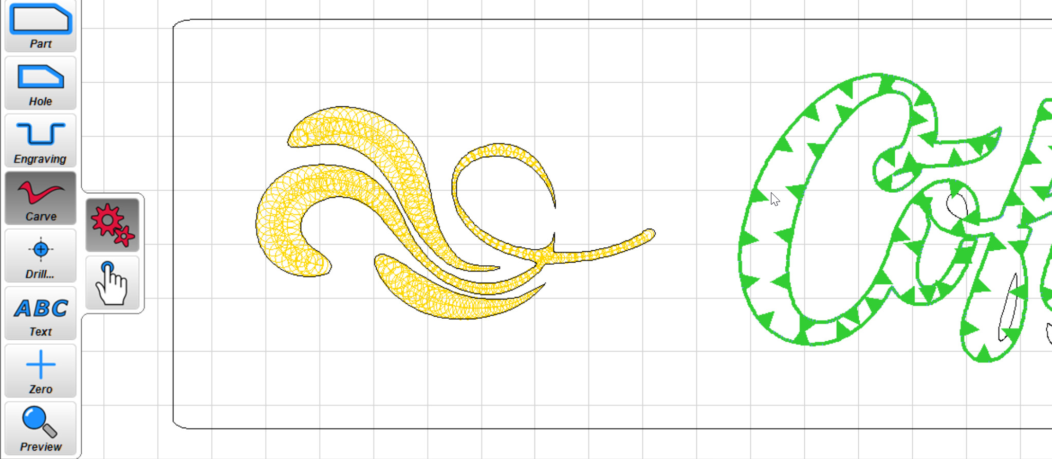
- Select the tool paths you just created and choose your v-carve bit. I’m using a 60deg Kyocera that has a very sharp tip.
- I set my Stepover to 3% to clear the bottom - this will depend on your bit.
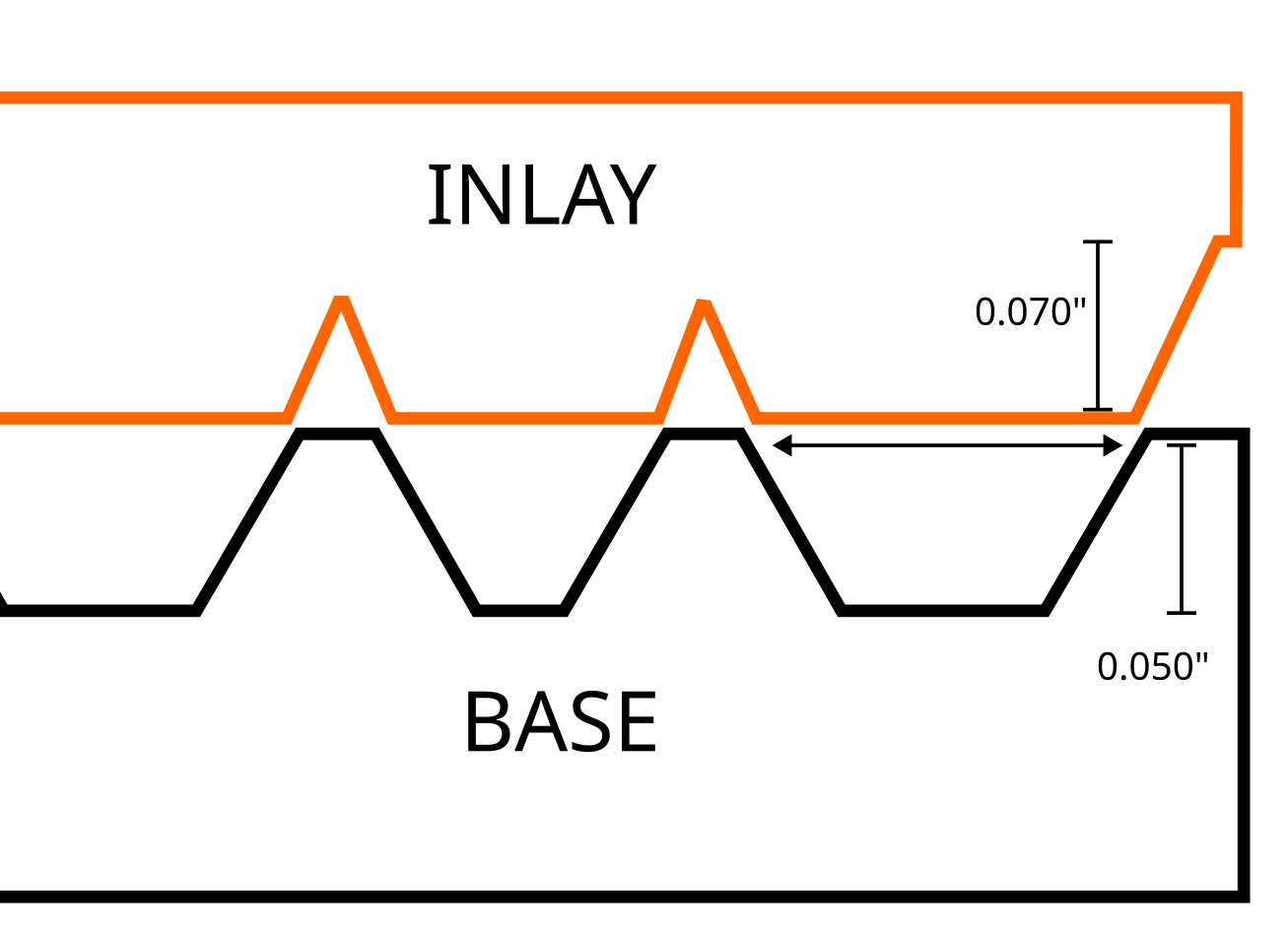
- Set your depth limit - I use 0.050". This does not need to be very deep to achieve great results. Adjust as needed for your project.
- Set a Carve pocketing tool. I’m using a 1/16" endmill since these are pretty small letters.
- Set Machine order to 10.
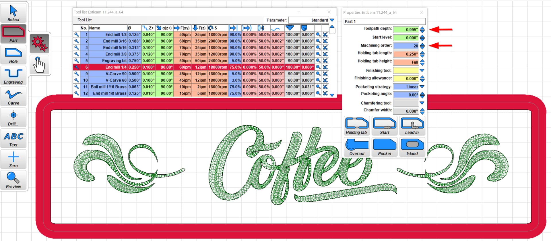
- Using the Estlcam “Part” tool, select your outer shape and appropriate bit. In this case, I’m using a 1/4" endmill.
- Set your Toolpath depth (I set mine to full depth of 0.995" for my stock, no holding tabs since I am using tape and glue).
- Set Machine order to 20
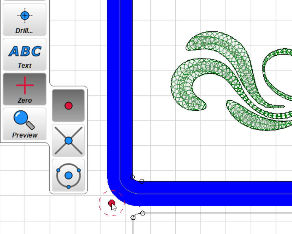
- Select the Zero tool and place the home point for your project.
-
File > Save Project to save your working file: Coffee Example.e10
-
File > Save CNC Program to generate and save your tool paths: Coffee Example.nc
-
File > Save Project As and give the project a new name to begin creating the next step: Coffee Example Inverse.e10
-
Select all your tool paths and delete them, time to start working on the reversed image!
-
Using the “Carve” tool, select the outside of your design.
- Select the tool paths you’ve created and select the same v-carve bit as before.
- Don’t forget those tiny inside loops, like the center of the “e”!
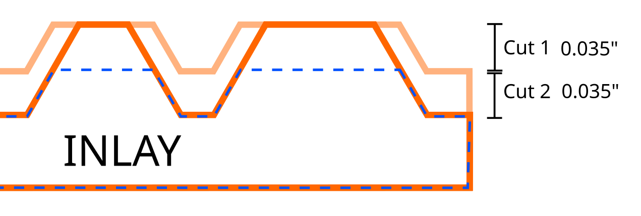
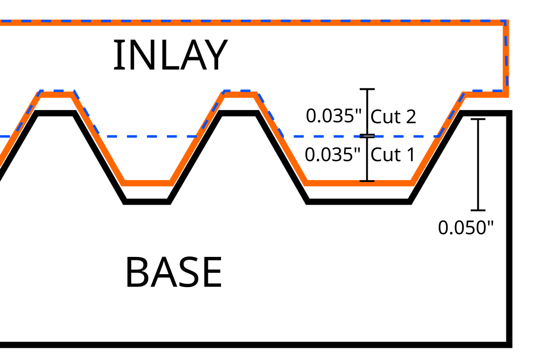
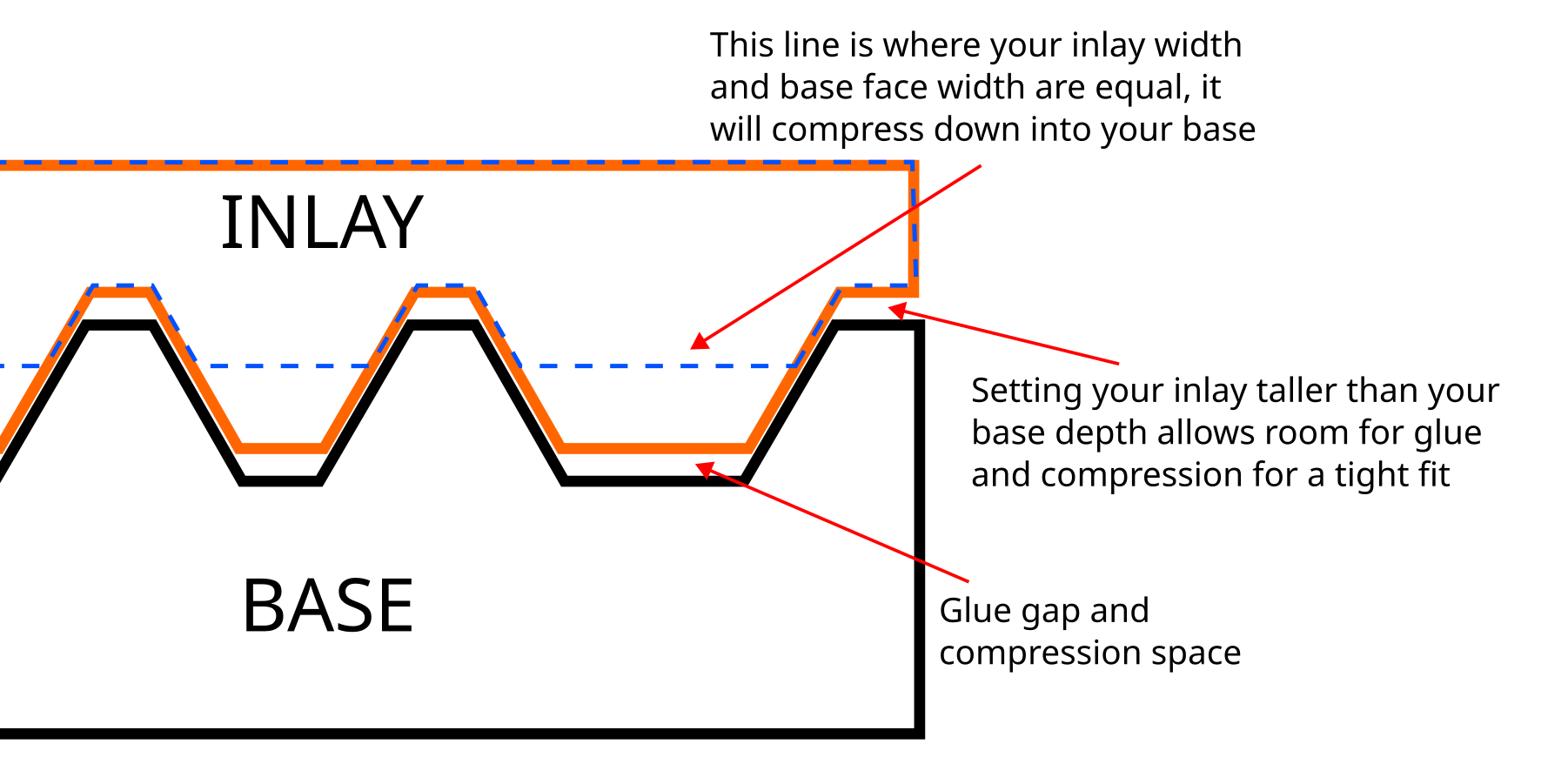
- (warning! math!) My depth on the first piece was 0.050", I want the inverse piece to be a little taller than that, so the total height will be 0.070". This is the first of two cuts we’re doing, so this cut will be 1/2 of the depth.
- Depth limit: 0.035"
- Start level: 0.000"
- Maximum carve width: 0.500" (adjust for your design)
- Carve pocketing tool: 1/16 endmill
- Machine order: 10 (IMPORTANT!)

-
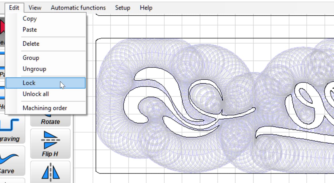
With the same tool paths selected, go to Edit > Lock. The paths will turn grey.
-
Repeat the same process, selecting the same tool paths with the carve tool.
- Depth limit: 0.035"
- Start level: 0.035" (IMPORTANT!)
- Maximum carve width: 0.500" (adjust for your design)
- Carve pocketing tool: 1/16 endmill
- Machine order: 20 (IMPORTANT!)
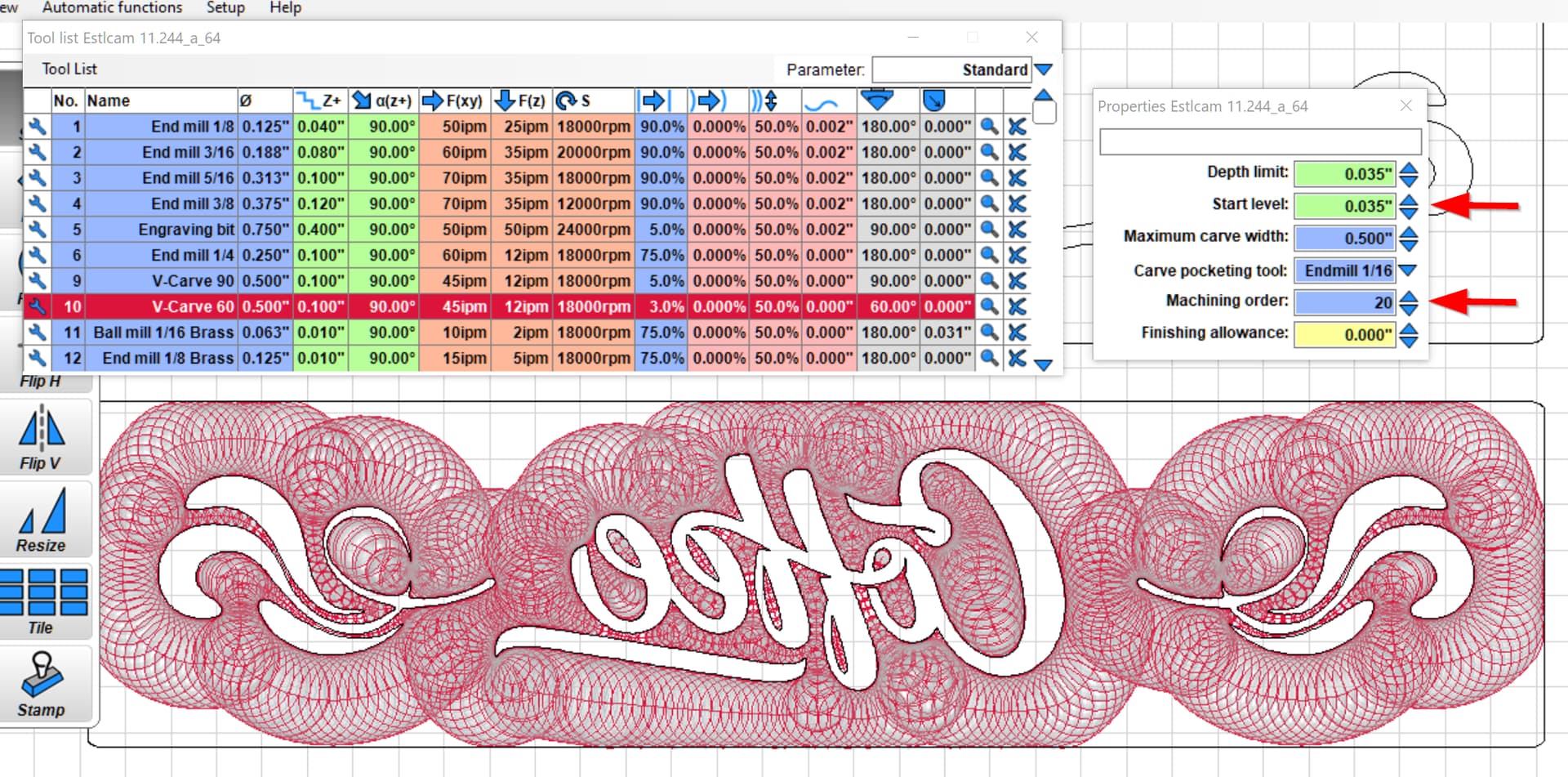
- Set your Zero location.
- You now have two tool paths stacked on top of each other. The first starts at 0.000" and cuts down to 0.035", the second starts at 0.035" and cuts down another 0.035" - a total of 0.070" deep.
- File > Save Project to save your working file: Coffee Example Inverse.e10
- File > Save CNC Program to generate and save your tool paths: Coffee Example Inverse.nc
- Optional This will save you some tool changes, but only do this if you are comfortable!
- Open your Inverse file in ncviewer.com
- Click on the gcode window and then ctrl-f
- Search for “m6t” - your tool order will be pocket 1, v-carve 1, pocket 2, vcarve 2.
- Reorder your tool paths to be pocket 1, pocket 2, v-carve 1, vcarve 2. Do this by selecting all the code for pocket 2, then ctrl-x to cut and ctrl-v to past into the new location after pocket 1 and before v-carve 1.
- On pocket 2, delete the tool change header as appropriate for your setup. For mine, I delete from (No. 3: ) to G04 P3 (which is the start of the new tool path to the pause I have for the router speed to ramp) as highlighted in image. This will allow pocket 1 to immediately continue to pocket 2 at the new depth without a tool change prompt. Do the same for v-carve 2.
- Save the new file.

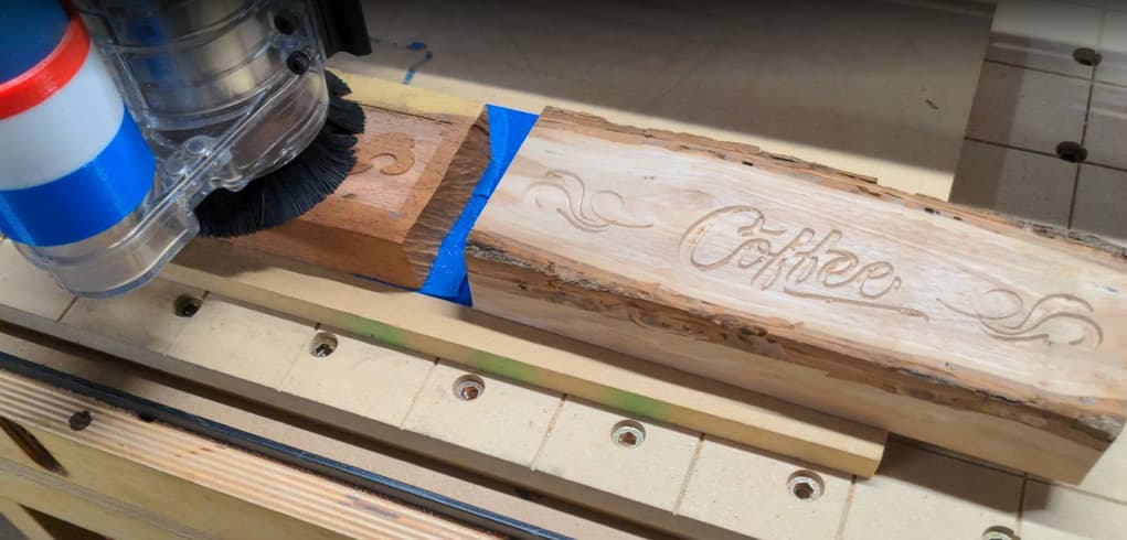
Your set up is now done! Go cut your two new files like you normally would. My next posts will show what we’ve done in this setup and then how to assemble and finish your new inlay project.
tl;dr (for those impatient folks, here it is in 6 steps!)
- Create your art in Inkscape
- Copy your art and create a mirror image with “flip horizontal”
- Import both into Estlcam
- For your “right” reading art, select the inside of the tool paths using Carve and your favorite v-carve bit, set the depth to 0.050"; save this tool path
- For your mirror image (the inlay) select the outside of the tool paths using Carve and your favorite v-carve bit, set the depth to 0.035", start level to 0.000", machine order to 10; lock these tool paths
- Select the outside of the same tool paths using Carve, set the depth to 0.035", start level to 0.035", machine order to 20; save these combined mirror image tool paths as a new name