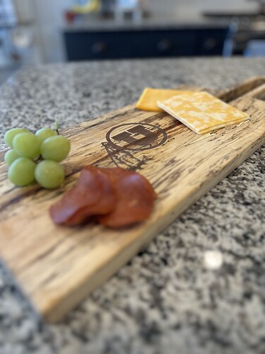
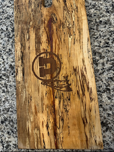
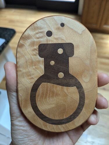
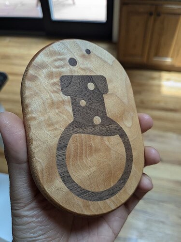
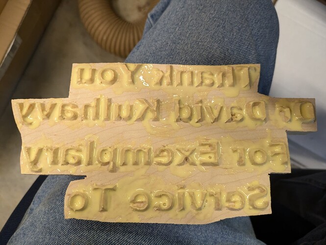
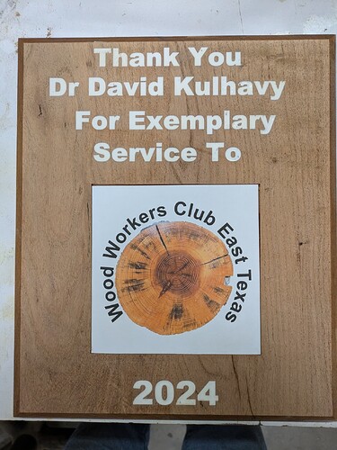
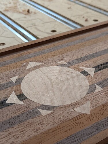
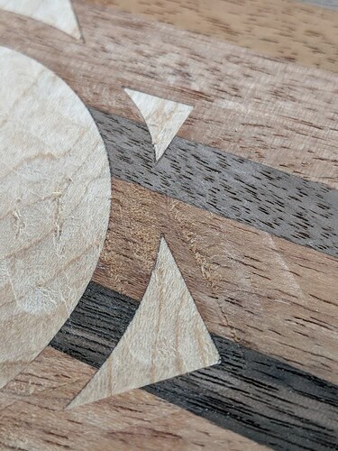
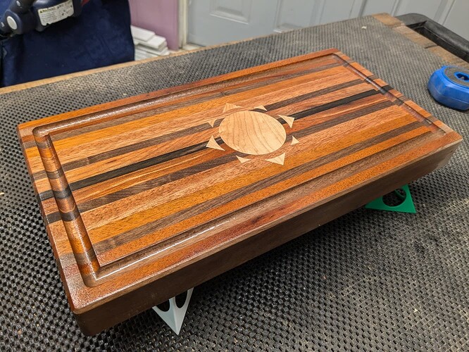
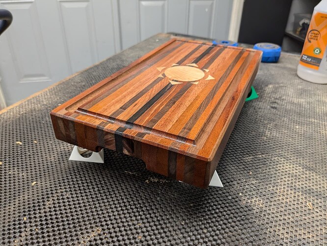
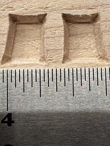
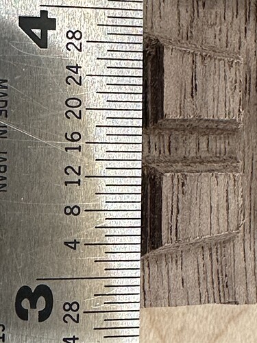
All sanded down and finished/staged. Thanks again for making this process easier. This was my second ever inlay.
@wmoy Thanks for your input. I wanted to get the female portion done and would have changed the material size to more closely match the size of what was needed for the inlay. Before carving the inlay I would have made the material size changed as well as thickness.
I will try this again but for this project the experiment is over.
I played with your files a little @gdon_2003. Maybe try something like this as an experiment and build from there, just a thought… Both socket and plug in one file but on two different layers.
Service Plaque.c2d (936 KB)
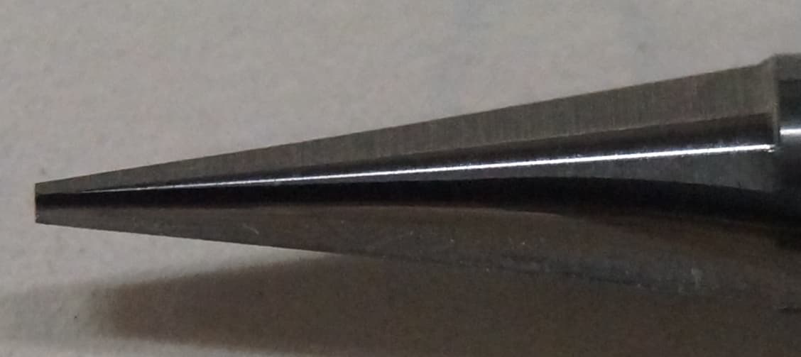
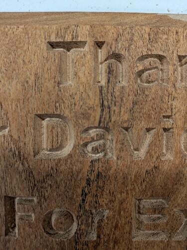
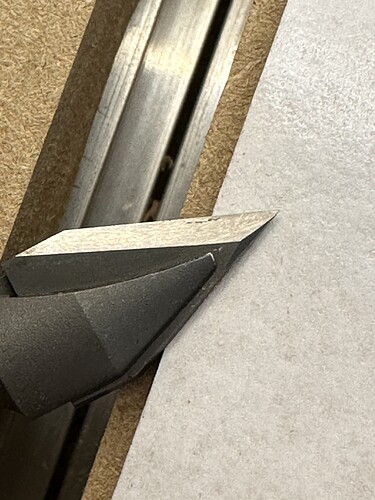
I discovered why I have a ledge around the inside of the lettering. I used a brand new 15 degree vee bit and I examined it before starting. It had a sharp point on it. However today when I removed the bit from the router and photographed it I found that the tip was missing. Not sure how it broke off. It had to have been when machining the mesquite because I am positive it had a sharp point to start off with.
So I will try the inlay on another project but for this one the die is cast and I was out in the shop setting up the scale and other things needed to mix and pour epoxy.
Here is a picture of the bit.
Many people here on the forum have bought vee bits that had a rounded nose and did not come to a sharp point. The issue with that is the BitSetter thinks it is measuring the sharp tip when in reality it is measuring further up on the bit. This results in a shallower cut than anticipated.
Ed, Thanks for looking. I took a look and it looks like you changed the bottom gap from 0.020 to 0.030 and changed to the #302 bit. I will try these settings on another project but this one is about to get epoxied.
I feel like ai lost the tip on a similar bit when it was hitting the bitsetter. I had an earlier thread asking if there was a way to slow down that initial plunge but didn’t really get an answer.
My bit was from IDC and they replaced it for no charge.
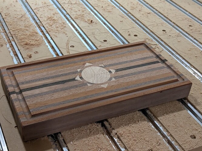
Chiming in with some success from the new inlay feature!
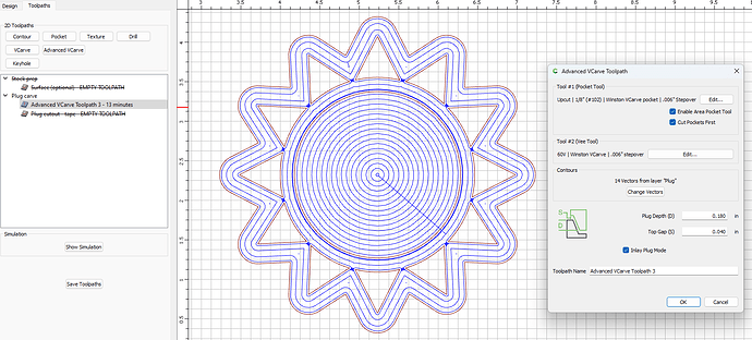
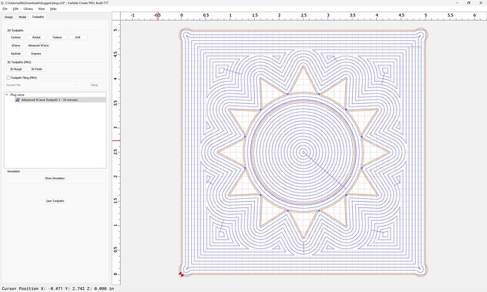
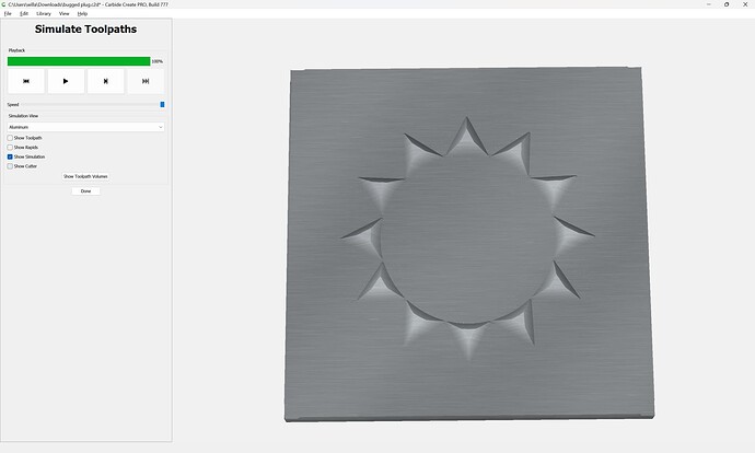
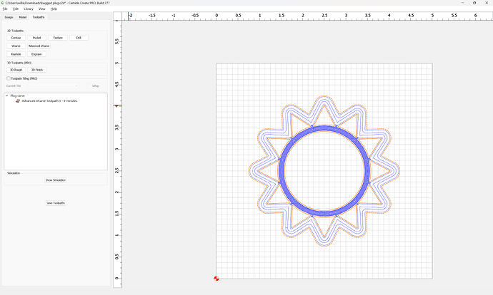
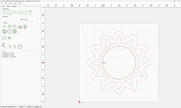
I am a bit confused though as I begin work on my second inlay. On the plug side, CC is not choosing to carve the portions of the vector that I’d expect. Given the outside offset, I’d expect the rays and the center of the sun to be raised, and everything in between to be carved. For some reason it’s trying to carve the center as well. This is the only toolpath enabled on the file. If I uncheck “Enable Area Pocket Tool”, the problem corrects itself, but obviously that setting isn’t suitable for an inlay ![]()
Any ideas? What’s especially confusing is on the female side it’s behaving exactly as expected, so I don’t think there’s anything wrong with the svg itself ![]()
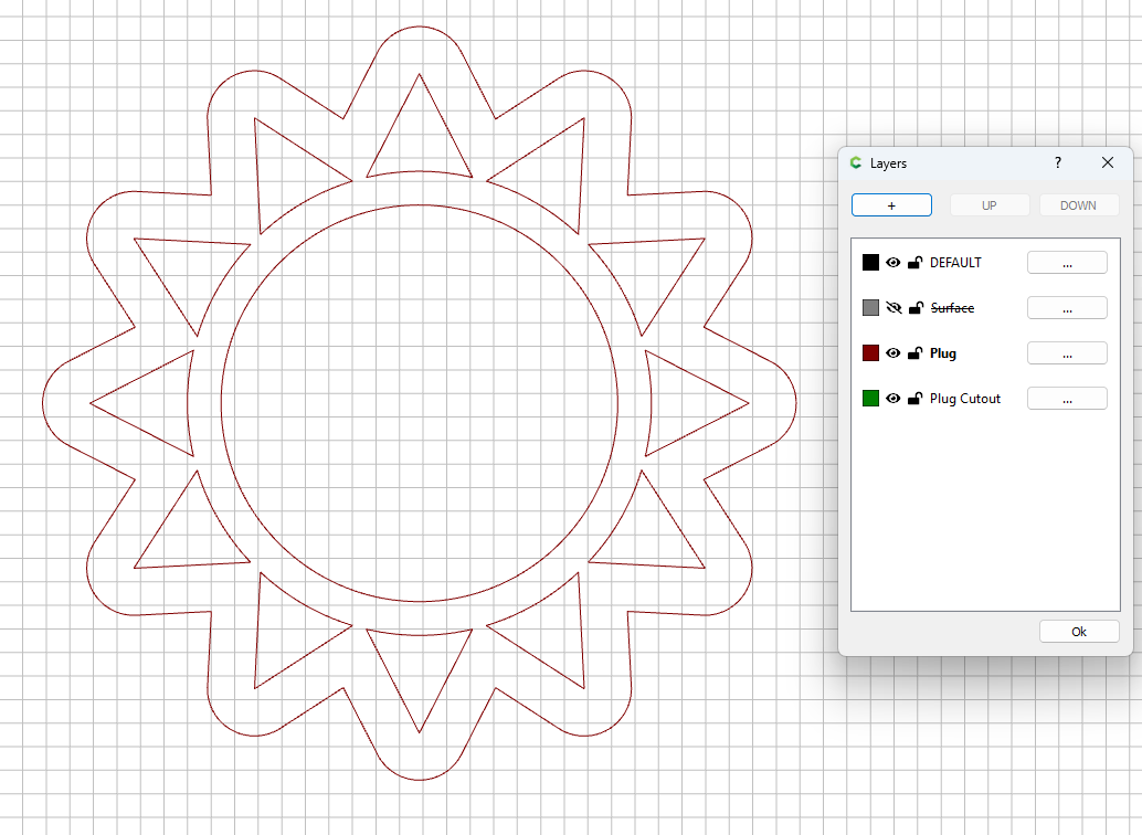
Here’s a shot of both pieces side by side. I’d expect the outer offset on the right piece to force the adv vcarve to invert all of its operations.
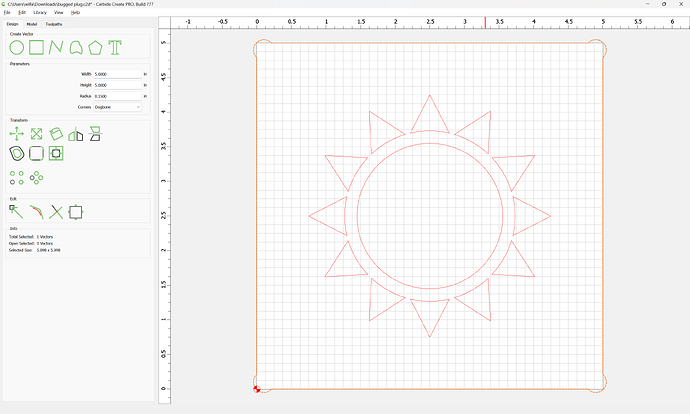
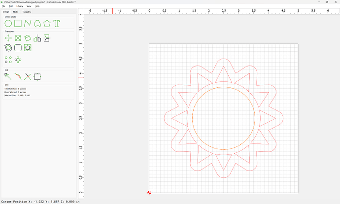
Here’s a simplified demo file for build 777. Hoping someone can point out a dumb user error ![]()
If you open that file you can (hopefully) see the problem in the toolpaths tab. Try inverting the VCarve by moving the outer offset line to the DEFAULT layer. Everything will work as expected. ![]() I’m really scratching my head here.
I’m really scratching my head here.
bugged plug.c2d (136 KB)
No, I am looking for the center circle of the sun to be raised so that it’s included in the plug. On the main workpiece side, that circle is (correctly) getting pocketed. Since the plug has an extra outside offset around the entire design, I’d expect all VCarve operations to invert.
This image might help understand my expectations. Red represents recessed area, green represents raised (part of the plug). The left shows what I’d expect with the configuration of that file, but instead it’s doing the right.
It’s as if the presence of the circle has no effect on the VCarve. In fact, you still get the exact same result if you delete the circle altogether! This feels very odd to me.
So this is bizarre. I tried shrinking the main graphic from 3.5" to 3" and it works as I’d expect. As soon as I bump it back up to 3.5", the problem comes back.
I just made this quick video to demonstrate:
OIC.
Although it’s circular, the central portion is not defined as a circle:
Re-drawing it as a circle:
does not change things, so this is definitely a problem with toolpath generation — filing a bug now.
Yes, I designed it as a circle in the source software (Affinity Designer) but I imported it into CC as an SVG. I had a similar suspicion to you and tried recreating it straight in CC as a circle as well to no avail.
One thing of note: If you delete any one of the “rays”, the problem goes away. So there is something about this specific design at this size + configuration that seems to trip up toolpath generation. It only breaks once I scale the sun above ~3.35", and is broken at any size larger, but works at any size smaller.
In the meantime, I redesigned this from scratch with some minor alterations and it’s definitely working as expected now ![]() so I’m unblocked, but glad we were able to pin down this weird edge case. (Also glad I decided to design the plug BEFORE carving the workpiece!) Thanks for taking the time to investigate, WIll!!
so I’m unblocked, but glad we were able to pin down this weird edge case. (Also glad I decided to design the plug BEFORE carving the workpiece!) Thanks for taking the time to investigate, WIll!!
I’ll post updates in this thread with the results from this inlay!
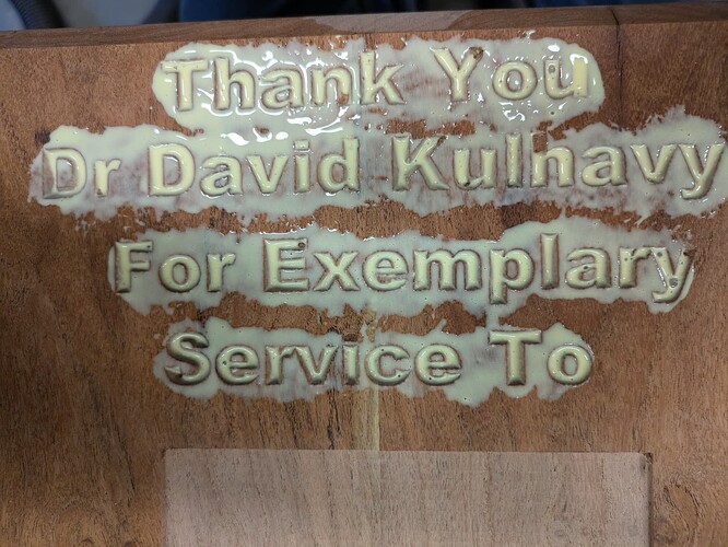
So I was inspired from some of the above posts and decided to give the inlay one last try. On my last attempt the tip was broke off my vee bit so I had a step in the bottom of each letter. So I filled it with epoxy and it is ok but I got the torch a little too close and burned the epoxy. It came out ok but I decided to try the inlay. @Ed.E had recommended I use a 60 degree bit and increase the bottom depth. So I did that. I used a 60 degree Cadance Manufacturing Groovee Jenny down cut vee bit. That bit is amazing and leaves an almost perfect finished surface. On the female pocket I used a 1/8" down cut but it was barely used. The 60 degree vee bit did almost all the work.
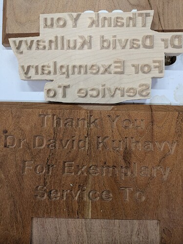
So then I made the male inlay using the recommended parameters from @wmoy and @Ed.E on some maple. It looked pretty good. After reversing the text and doing a .30" offset I carved that with a 3/16" down cut bit and the 60 degree Jenny bit. I originally tried a 1/8" but the time to carve went way out and a 1/4" barely cut anything and would have made the vee bit do all the work. A vee bit does good at some things but clearing is not it forte.
I applied TiteBond II. That is what I had and works well but sets very fast. I am out of TiteBond III at the moment and that has a longer set and working time.
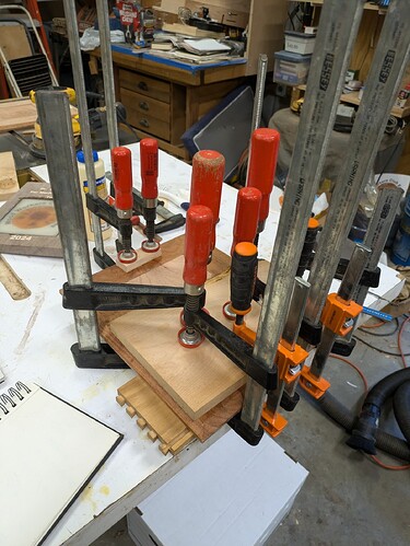
I got it all clamped and will see tomorrow how it came out.
Keeping my fingers crossed. I want the inlay to work but this is my last attempt. I have had so many failures that at some point I just change gears and go with something else. Hopefully with all the advise I got it will work.
Here is the previous one I epoxy filled.
Great results with my sun inlay!
Here are some of the (very minor) issues I ran into, in case this helps anyone else:
- Material selection: The maple plug was chipping a bit during VCarving, so naturally there would be minor gaps after glueup. This maple had some light figuring which always presents challenges with machining. Probably best to stick to plain hardwoods, at least for the plug, where you’re likely to need the finest details.
- Clamping/glueup: My previous inlay was a tiny test piece, so it was easy to get clamps around it. On bigger pieces like this you need to a plan to get pressure on it during glueup. I opted for a bunch of stone blocks and while it seemed to work okay I am sure the pressure was uneven and doesn’t compare to the 100s of lbs of force from tightened clamps. I’ve also seen folks online use mallets to make sure it’s fully seated which is something I’ll try next time, but I still need a better solution for sustained pressure (tips welcome!)
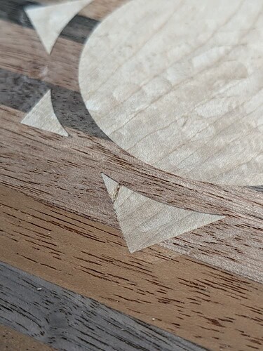
- Plug trimming: I decided to experiment with using a rough hogging bit (The Beast from IDC Woodcraft) with very aggressive F&S to see how quickly I could remove the plug. It worked, but as you can see in the 4th pic, it seems to have taken a tiny chunk of the inlay with it (probably due to the figuring in the maple). Next time, I’d probably just go a little slower with a normal 1/4" upcut bit, or use my bandsaw first. I also don’t have to trim it so close to the workpiece and can just remove the remainder with a handplane. I suspect a handplane would also avoid the “smeared sawdust” problem Winston presented in the video.
Overall I’m very pleased with it. Thanks again to the C3D team for putting attention into this feature, and to Winston for the incredibly detailed video. It’s really reignited my love for CNC ![]()
Bonus tip: I highly recommend setting up “template” files for repeatable tasks like this. I created inlay template files with all layers and toolpaths pre-defined. I used layer-based toolpaths rather than vector-based to make swapping out art easier later. Having everything pre-defined like this is especially helpful for the Adv VCarve toolpaths on the plug.
Aside from the bug I ran into yesterday, my second inlay went much faster than the first utilizing this template. I just made a copy of the template, adjusted stock settings, and imported my art into the appropriate layers. For me, this is way more preferable than waiting a few months, trying to remember which project I last did an inlay on, and hunting down that file as a starting point. The last project may have had some quirks that forced you to make some unusual settings, and you might have forgotten. Or maybe you forgot you had an even more recent project that has a bunch of toolpath improvements. Maintaining a simple template file means I always know where to find my most up-to-date, hard-won knowledge and tricks.
Just be careful you make a copy of the template and don’t accidentally overwrite it ![]() I make my template files Read-only to prevent careless mistakes.
I make my template files Read-only to prevent careless mistakes.
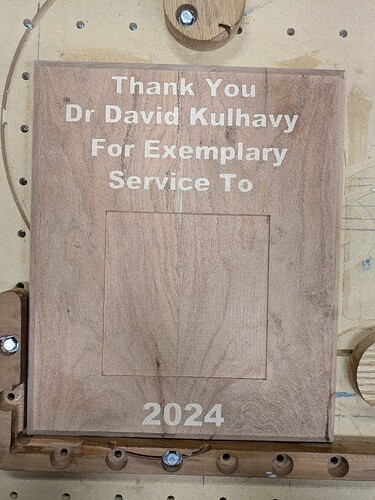
Well I will call this a success. After multiple tries everything came together. There was a small problem but that was an operator error. When I glued the top half of the male inlay somehow I did not get the wood pressed down as far as I should have. The outcome is acceptable but I guess I just did not look under my clamping board to see that I had enough pressure. The bottom inlay that was 2024 came out perfect.
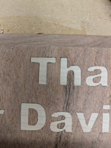
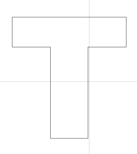
The “T” looks off but further down where the inlay was perfect the “T” was a little off on the right side of the top bottom of the “T”
That might be something with the font but it caught my eye.
Here the the whole thing and it looks acceptable.
So here are my files.
Service_mesquite_60degree_female_pocket.c2d (276 KB)
service_mesquite_exlempary_male_plug.c2d (528 KB)
service_mesquite_keyholes.c2d (248 KB)
On the male inlay I used a 3/16" down cut bit to do the clearing. I tried a 1/8" and a 1/4" and the 1/8" took forever and the 1/4" barely took anything and the vee bit would have done all the work. So since I had the 3/16" bit it was just like the 3 bears that was just right.
Both the male inlay and the female pocket I used a 60 degree Groovee Jenny bit but a #302 would have worked.
In my previous versions I was using a 15 degree vee bit. That made for more of a flat bottom but with the 60 degree bit the bottom of the letters was basically a V shape.
So the main lesson was to increase the bottom gap from 0.020" to 0.030" and the female pocket was cut to .20" but the male inlay was cut to .18". So if I would have seen that the plug was in a little crooked I think it would have been a little better.
Sometimes perfect is the enemy of good enough.
Once I get the plaque finished I will post a final picture.
Edit. I opened up the female pocket file and zoomed in on the “T” and it appears symmetrical on both sides of the “T”. So in two locations the T has an odd shape. Perhaps the direction of cut but it is not the font.
The font is Arial Black which is just a block font. Being a simple font is the reason I picked that font.
First attempt at inlay, thinking this is more machine than software. Brand new 45deg vbit, but my lines arent straight, corners curve out. Any suggestions?
What exact bit are you using? Seems like maybe the geometry of the bit doesn’t match the ideal-case which CC uses to calculate with. Perhaps the tip of the bit is rounded vs pointy-sharp?
ShapeokoProXXL
HDZ
carbide router, speed setting 3
Spetool 45 bit, very first cut out of the package
“ SpeTool CA W06014 Carbide Tipped V Groove 45 Deg 1/2" Dia x1/4" Shank x 2-1/4" Long Router Bit “
Surfaced the board, then
0.6mm glue gap
3.0mm pocket
1.5mm top gap
This is the he/him side of the cut
Thanks
