Inlay with 30 degree bit

Hi group,

I am having a hard time succeding my inlay with this SPE 30 degree V Bit.

Has anyone succeeded with it or any other 30 degree V-Bit? If it’s the case, how do you configure the bit in CC?
I copied the Carbide create #302 60 degree v-bit and change the “Included Angle” from 60 to 30. Nothing else.

But when i look at my result, the male piece is never perfect for the female. There is crack at many places.It’s either the glue that fill it or just nothing.

Help!

I think we’d need to see photos of how your current projects are turning out and the C2D files to see where they might be failing.

2 Likes

Also, have you updated to version 830 or later of Carbide Create? There was a bug with the angles being inputted in earlier versions.

2 Likes

I prefer this bit for Inlay.

SpeTool has a Carbide 3D speeds and feeds spreadsheet on thier website.

1 Like

Yes, I am using 835.

Ok but how do you create/set it in CC?

I know, I tried it and no good result.

Martin, inlay in edge grain IS a nightmare, especially for fine structures - sharp angles. While carving out will succeed, the counterpart needs to have a sharp edge that fits in, and that breaks easily because alongside the grain the wood has not much stability.

Either use end grain for inlays, or round patterns without sharp edges/corners.

Here are picture of my result. I know I am on edge grain and i have broken grain/part but I just want to test if it fill the layout.

I Just added photo in another reply

I understand that about the grain. But my problem is to fill up the main part of the layont and not the detail.

Martin, appears to be a problem with depths, so that the glue gap might be not deep enough, or mechanical deviation from pulling the bit towards the cutting edge. do you mind copying the project here?

2 Likes

Can you post the file?

Test 57 V30 F.c2d (416 KB)
Test 57 V30 M.c2d (704 KB)

Well, I don’t have the same version you have. Ugg.
Based on your pictures I assume the male plug start depth is not deep enough.

Here’s my updates.
Female Pocket depth 8mm same as you had. I did add a Facing Toolpath.

Plug
Manual Toolpaths.
1.5 to 3.5
4.5 to 6.5
7 to 9
All Advanced V-Carve using 30 degree v bit.

I did change the clearance tool on the plug to a .25 EM to save some time. The Female side I kept the .125 EM.

FYI, I added a facing toolpath to both. I have found that facing the stock makes a big difference, especially on the fine details. Make sure to REZERO the Z after you face off the stock.

Female SD guy Edits.c2d (404 KB)
Male Side with Manual Plug Toolpaths in MM SD GUY edits.c2d (1020 KB)

Here’s my latest inlay. It’s not 100% done, but its looking pretty darn good.

4 Likes

Thank you very much for all the effort you put into this. I opened your file and look at it a lot.

Question : If my CNC spoilboard is flat and the piece of wood I am using is flat from the planer. Do the step of surfacing it really useful?

Also, I saw you did the male plug in 3 steps, Why don’t you use “Depth per pass” parameter in order to take care of that, Is it going to produce a different result?

I am using the “Inlay Plug Mode” that take care of the Plug Depth and Top Gap, Is it creating a different result than yours?

In “Simulation”, both way look like they produce the same thing. I am confuse if I should use or not that “Inlay Plug Mode” that look like being created by CC to manage all this.

Thank you again.

1 Like

Inlays are a much higher tolerance operation than a typical decorative project or sign.
The spoilboard should be flat, but also parallel to the XY plane of motion. Same with the top surface of your workpiece.
The machine should first be squared, calibrated, trammed & surfaced.
You can check the ‘flatness’ by touching off to several spots on the top of the workpiece & checking the Z values. Planers are not always high precision tools. Wood also tends to move. If the wood is a little warped the planer may bend it flat while cutting, but it can spring back after planing.
It’s a good idea to surface the workpiece when doing inlays.

Your first image of the “57” inlay looks much better near the center of the workpiece, and worse as you move away from center. This could indicate a non-flat male. If the stock was higher toward the outside, that portion of the plug may be bottoming out before it is snug in the pocket.

Inlays can be done with or without the inlay plug mode. without it, the depth where the vector is traced is determined by the Start Depth. With Inlay Plug Mode the depth where the vector is traced is determined by the plug depth. Inlay Plug Mode allows you to use depth of cut from the top surface. Whereas without plug mode you need several paths to establish a depth of cut.
So, yes you certainly can use the Plug Mode with depth of cut.

Here’s cheat sheet showing both that helps me keep track of what the parameters do

I’d suggest starting with a test. Something simple, like this with the pocket & inlay hanging off the edge of the workpiece so you can see the fit. (Or you can assemble them & band saw them in half.) Start the male with a plug depth of 2.5mm and a Top Gap of 3mm. (Still a total of 5.5) Expect it to fit high & need recutting. Clamp them together and measure the actual plug depth. Now adjust the plug depth & top gap to account for the difference in the programmed value & measured value.

3 Likes

For the Facing toolpath. If you are 100% confident that the planes are perfectly parrallel then you can skip the Facing Step. In my humble opinion, knocking off .5mm to ensure the surface is perfectly flat to my machine is worth it. Escpecially if you are doing some fine detail. It doesn’t take much to screw up an inlay. Secure you stock, run a pencil over it, touch off, set your Z, run the spindle to all four corners of your stock and the middle. Just verify the stock is actually perfectly flat and parallel to your machine.

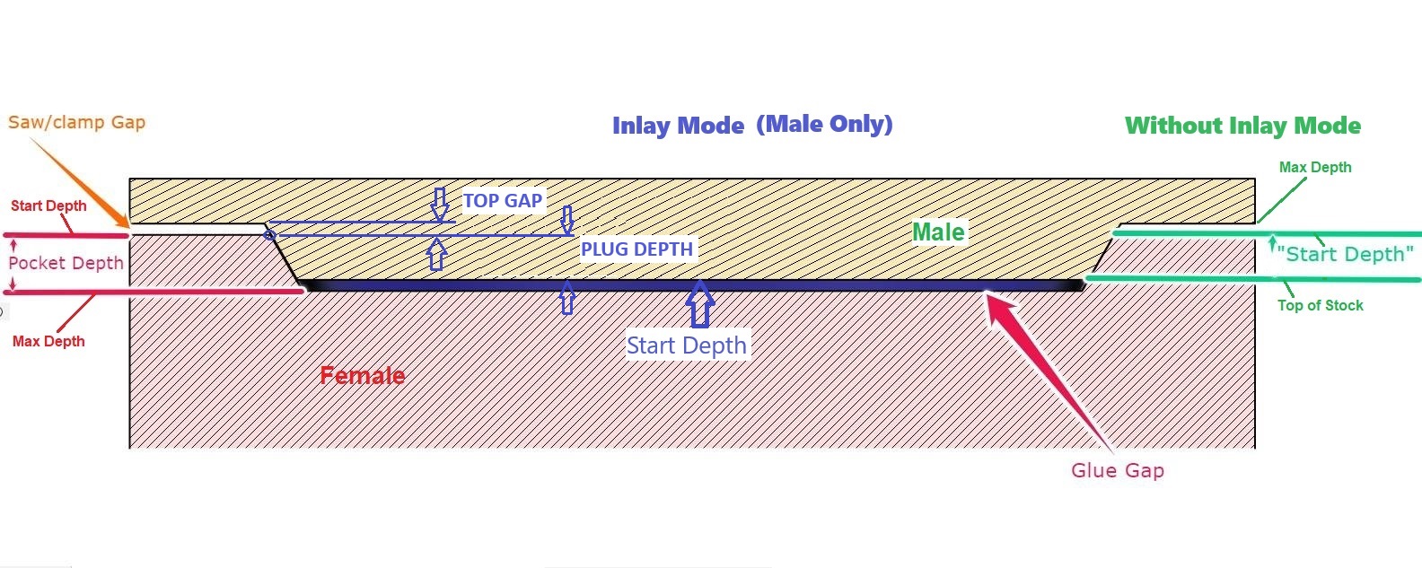
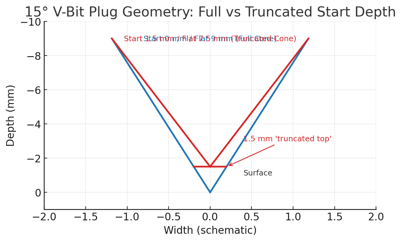
I didn’t use the Depth per pass because it changes the geometry of the carve. I can’t explain the math, but here’s visual. The blue would be a regular advanced V-carve, while the red is the manual 3 step v carve. I asked Chatgpt to explain this to me and this is what she produced, so like I said I can’t explain the math, but this is a representation of the difference.The “truncated top” allows for the bottom glue gap.

You can use whatever method you choose to do your inlays. The numbers I provided are proven numbers and proven toolpaths. I am sure CC has done a lot of homework to made the inlay mode work, but I do see a lot of questions on it. I am a keep it simple stupid type person, if it ain’t broke then why fix it.

Also, you can use my inlay toolpaths without having to buy CC pro. Using CC 8 and up you can group the toolpaths so you have less bit changes, which makes it nice.

FYI, there are also some “pro” tips. I can share.
Fit Adjsutment tips.
If the inlay is too tight. Reduce the Start Depth slightly.
If the inlay is too loose, increase the start depth slightly.

You can also “cheat” your toolpaths by slightly adjusting the angle you have the tool set to. IE use a 30 degree v bit but in the software change the angle to 29 of the plug only. This will also tighten the fit by a few thousandths.

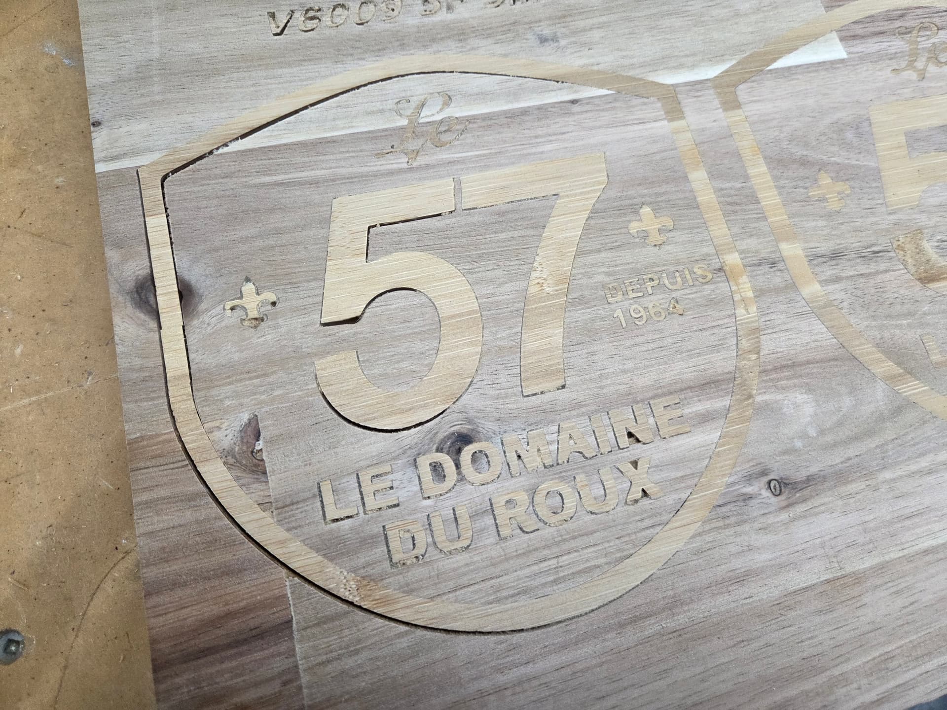
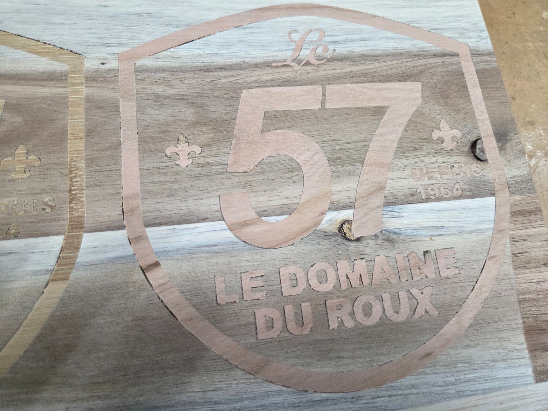
After you carve both the inlay and the plug, let the wood “rest”. At least overnight. The allows the internal moisture of the wood blance after exposing new grain. If you are doing a DEEP carve inlay let it “rest” longer.

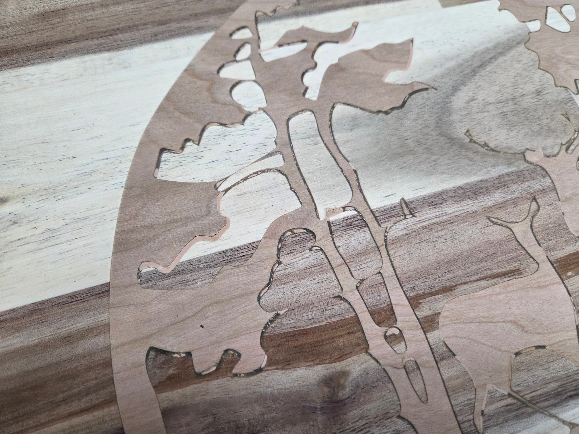
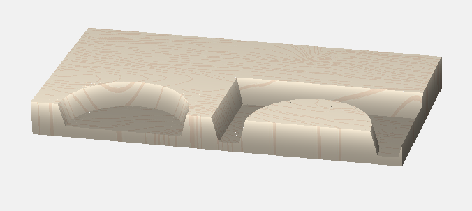
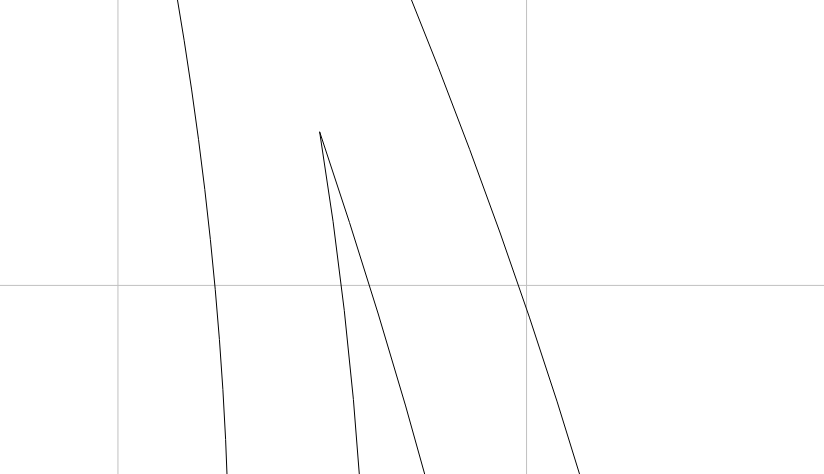
Another Pro-tip, remove any pointed Vectors.
This is a No GO:

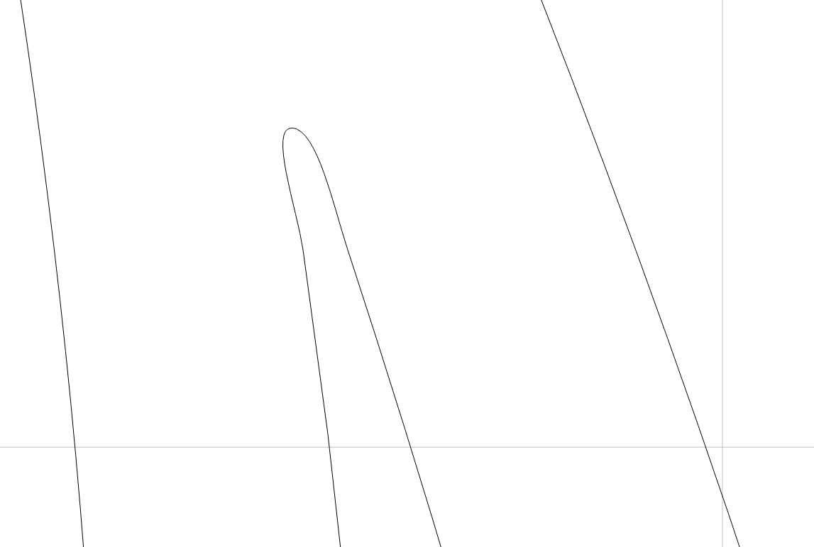
I added two nodes and smoothed it out. This point works.

The DOC at the tip of the Sharp point will be too shallow for the plug to penetrate, it will likely break off and or be too easily sanded off, leaving the female carve showing. You can just use some glue and saw dust to fix. I just remove all these really sharp points from the Vector.

I hope these pointers are helpful. I have spent MANY hours FAILING at Inlays, going back to the drawing board, watching YT videos and trying again.

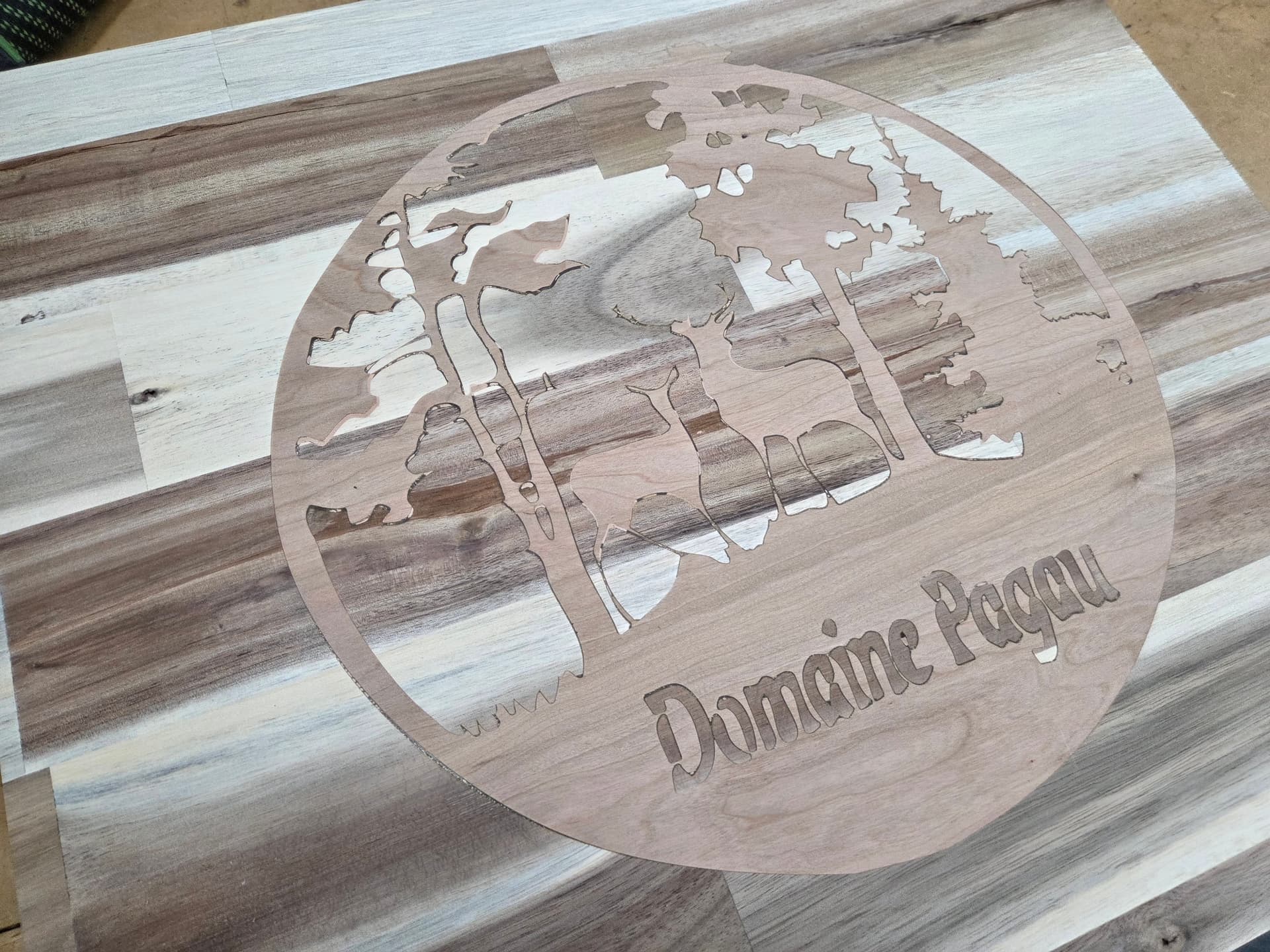
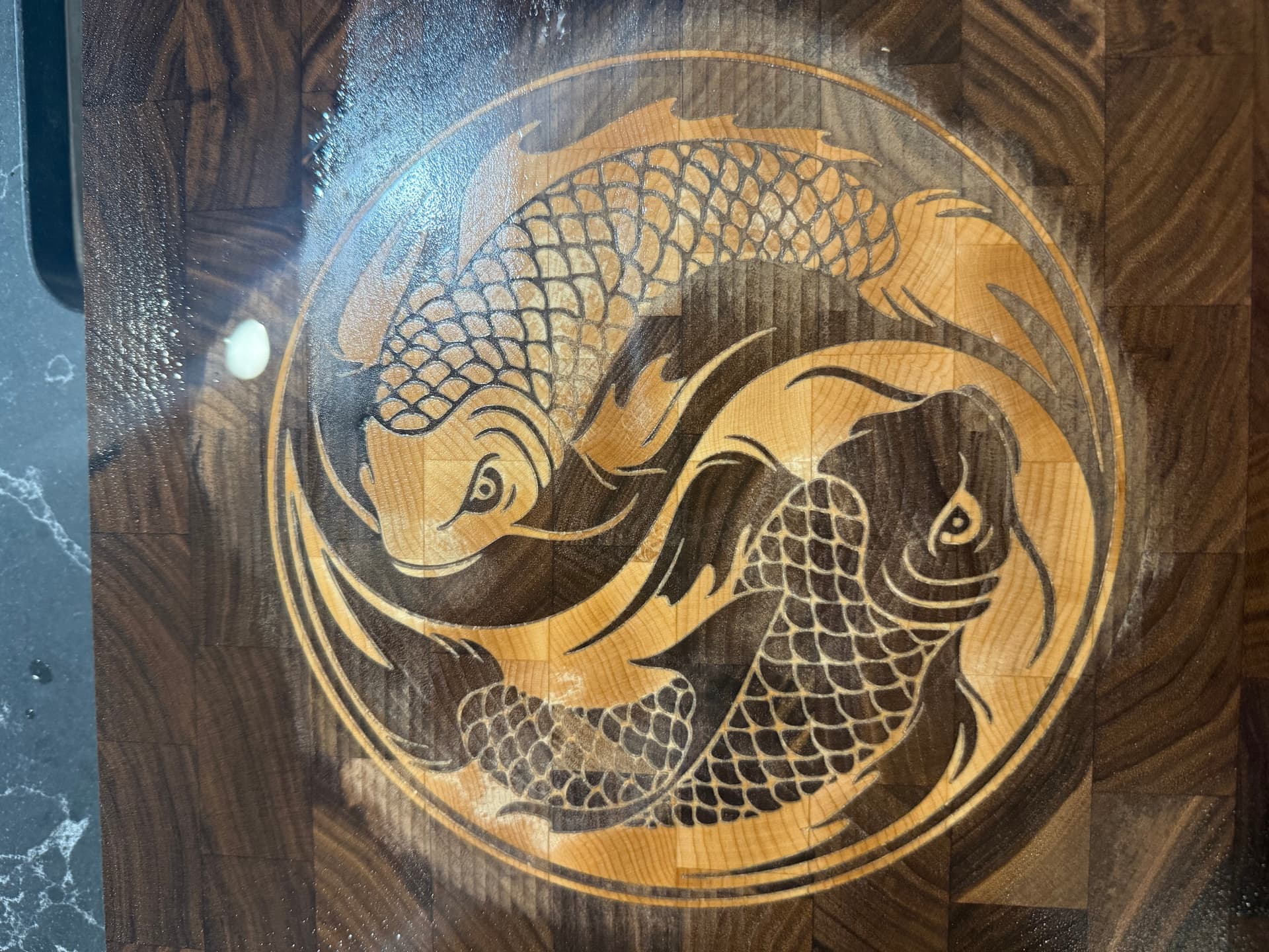
Also, I suggest practicing on a simpler and easier to carve design. Here’s a good starting point.
YT logo simple

3 Likes