No idea what im doing wrong, but whatever i do the male plug is always to loose. Ive followed the tutorials on here to the T, along with other software tutorials hoping I could find an answer. Ive dove deep into the bowels of the forum and read the other inlay issues, but come up with nothing helpful
I cut both male and female with the same bits. Ive tried different start heights, and glue gaps. Each time i get the same loose male plug.
Have you tried one of the example files from the thread:
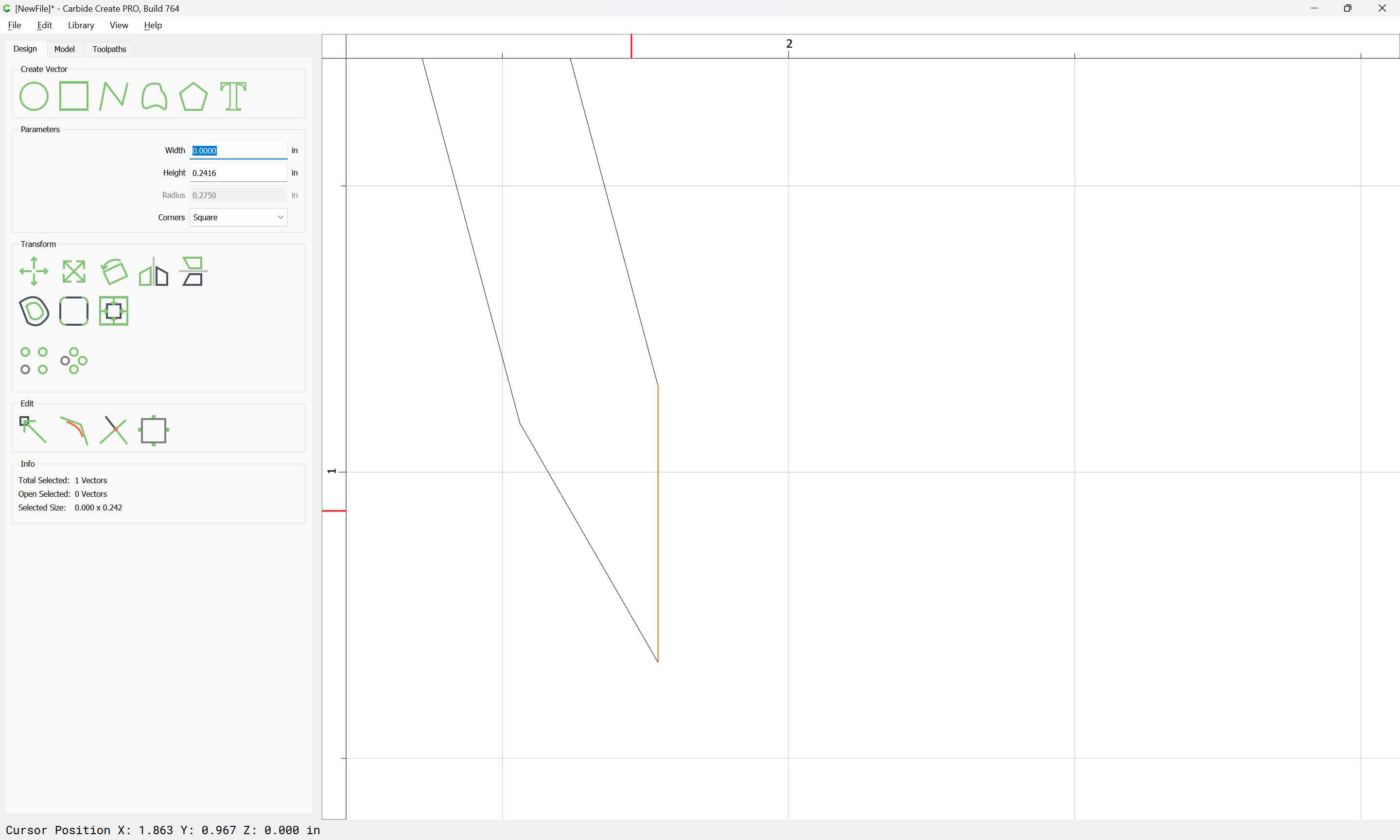
Post your .c2d file, step-by-step notes on how you are securing your stock and setting zero relative to it and managing all tool changes and a photo showing an attempt at cutting still in place on the machine with the machine at the origin or a specified offset from there?
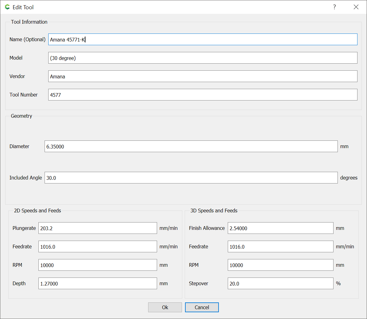
I cant use a 60 because there is fine detail that would be blown out.
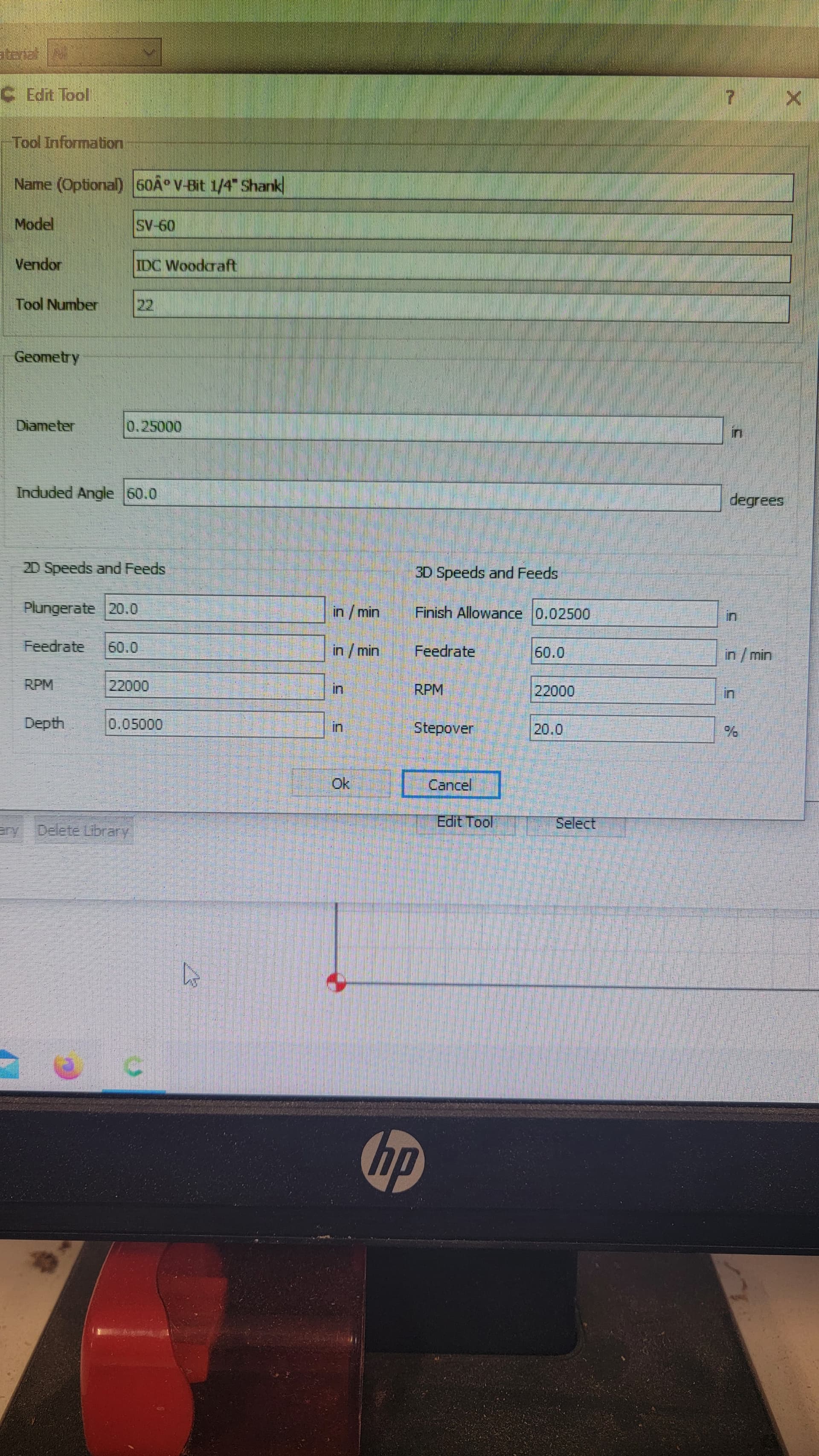
But for the 30 v bit I use the 1/4 version, would that make a difference? In my tool library its labeled as such. As for the flute length, is it pretty universal among manufacturers?
I will say that I have not tested the bits angle, but I have tried two separate bits from IDC, both were 30s, both gave same results.
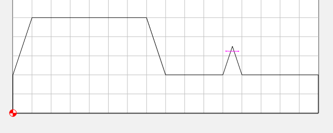
The calculations/cutting for a V tool require that the tool geometry in the software match the physical tool.
One possibility would be to adjust the angle slightly to make up for this rounding — might be worth a test cut — it would slightly increase the material removed, esp. at the bottom, but that might make driving things into position easier.
Im not sure if it does, ive always gone by what the simulation is showing. And when I switch to a 60 v bit, some of the detail gets removed.
The rounding over from the bitsetter seems logical. Would it be possible to recut my female pocket with the 60 V, since i have not removed the project from the spoil board. I could just adjust the project to work with a 60 V
Actually, on second though, the 30 degree, being more acute would have removed more material than the 60 would — it would work to go the other way though, which I guess is what I was thinking.
I should just be able to rerun my adv v cut just swapping out the 30 for the 60 right? I haven’t removed the piece from the spoil board yet, or do I have to plane the project down and start over?
Your setup in CC looks right. The 0.010 gap may be a little small, but you said you tried with larger values.
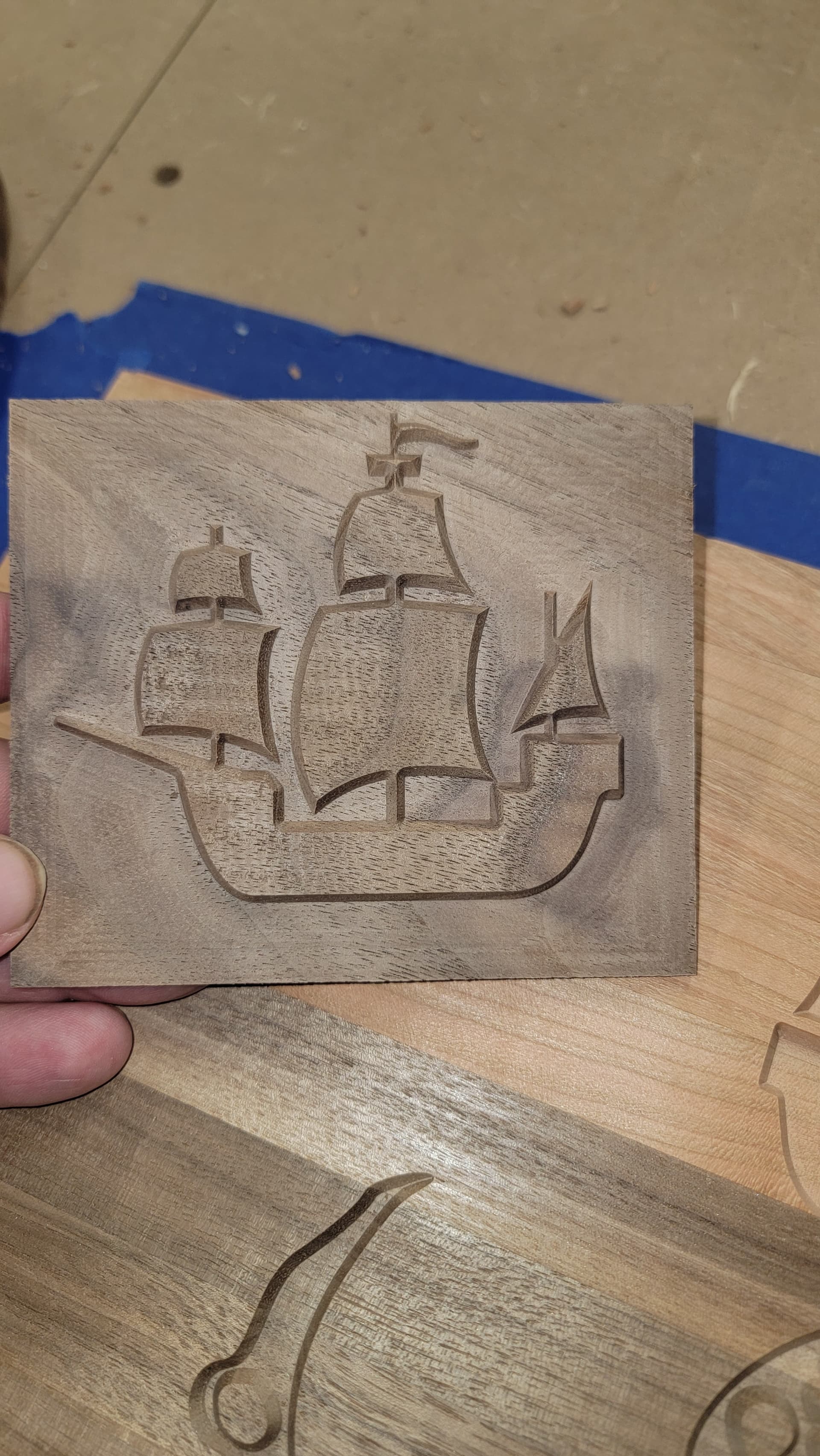
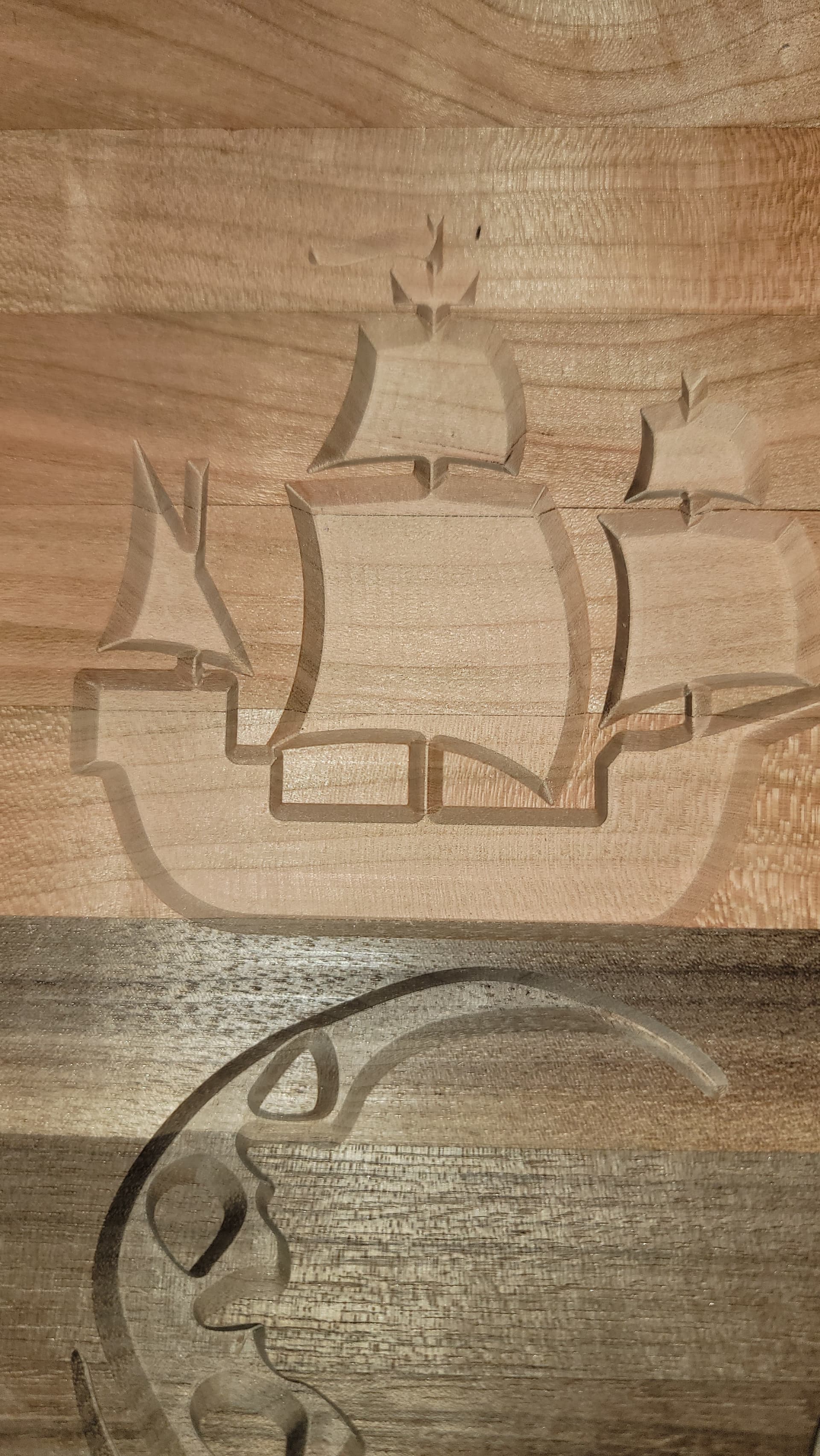
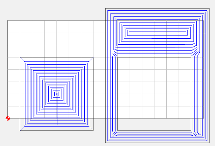
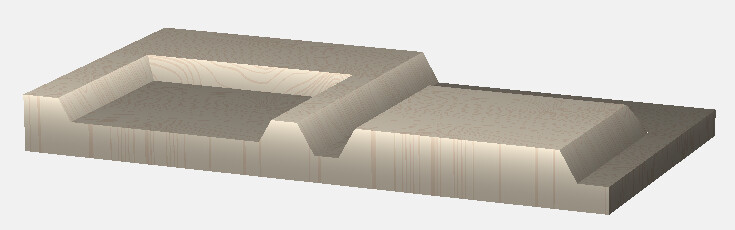
Do a test like this, where the pocket & inlay overlap the edge of your test piece. You can put them together & see the fit. The features are even sizes, so you can also measure them to see if they are cutting to the right size.