@SLCJedi doesn’t it top out at 200 ipm?
Has anyone with the 4x4 and VFD spindle kit try to extend the spindle to VFD cable? Mine only gives me about 24" of play from the back of the machine, which is nowhere near enough to be able to bring the controller to the front of the machine so I could utilize the spindle disable button on it. Is extending that cable even possible?
1 Like
The default grbl settings do top out at like 197 IPM. But you can edit them up to 275 IPM. It is not recommended and I’m going to limit myself to 200 for projects as they recommend anyway. This was just “because science”. ![]()
@jakesmakes, I’m with you. I’d love to get my VFD closer to the control box.
2 Likes
I extended the VFD cable on mine by about 4-5 ft so I could mount it under the table next to the main controller. I didn’t on mine, but I imagine you could also extend the wiring of the spindle on/off switch just as easily if you wanted to bring it to the front of the table. The rpm screen on the VFD is detachable and just uses an RJ45 to extend that to the front as well.
Obviously it should go without saying if you aren’t comfortable with electrical wiring then don’t attempt it.
If you want some more info on how I did it, I can write up some more details and I think I’ve got some photos of it as well.
4 Likes
If you could that would be amazing
1 Like
So the cable they use for the VFD is an Igus chainflex control cable CF130-UL which has 4 18awg conductors. If you happen to have some of that on hand great. I didn’t, but I did have some other nice 18AWG copper wire that I could use.
First off you will need to open up the VFD box, once inside you will see something like this.
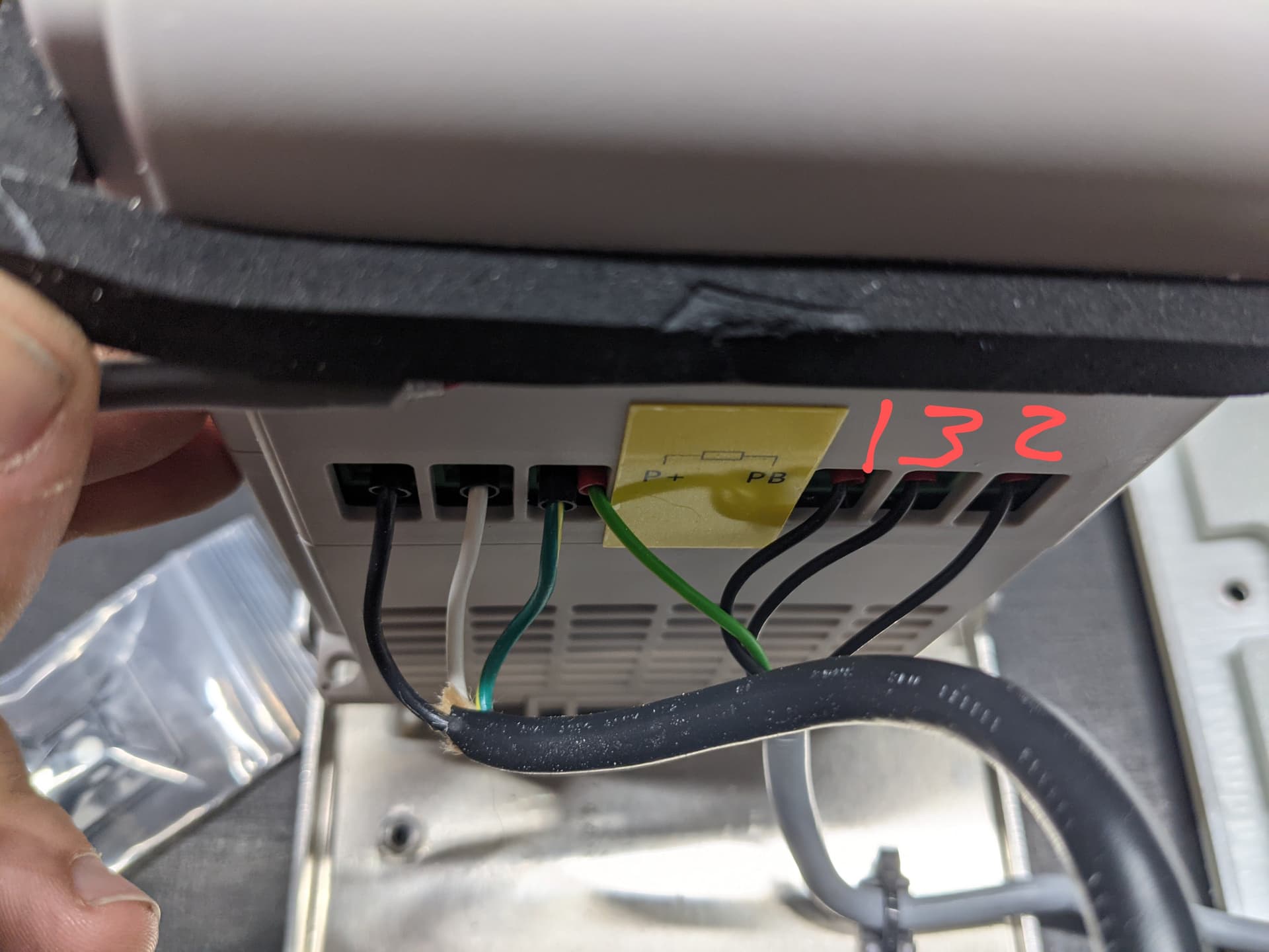
The left side is the mains power, Black is hot, white neutral, green ground. The right side is what feeds to the VFD. You have a ground, and 3 black wires. On the insulating jacket they have markings of 1,2 and 3. This order is important. My photo is marked up how they were ordered on mine but always verify with yours as well.
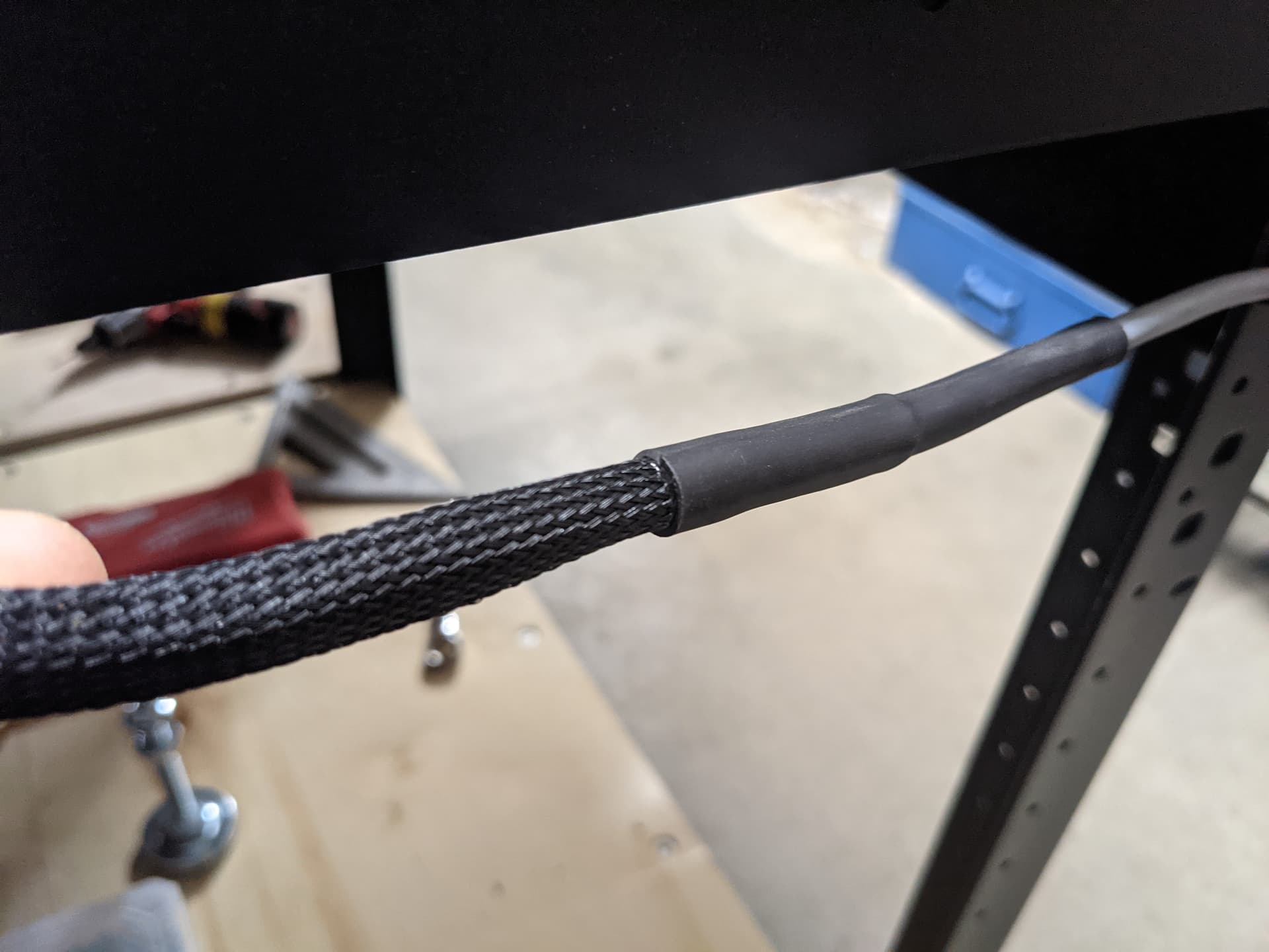
These are the wire you will want to disconnect and extend. I just cut the sheathing back another 6 inches or so, cut off the original ferrules and used heatshrink crimp connectors to splice in the new wires in, staggering the crimps so that the cable didn’t have a huge bulge in one spot. I then also put some nylon braided sleeving, with heatshrink on both ends to hold it into place, over the section of cable that comes out the back of the shapeoko to give it some more protection.
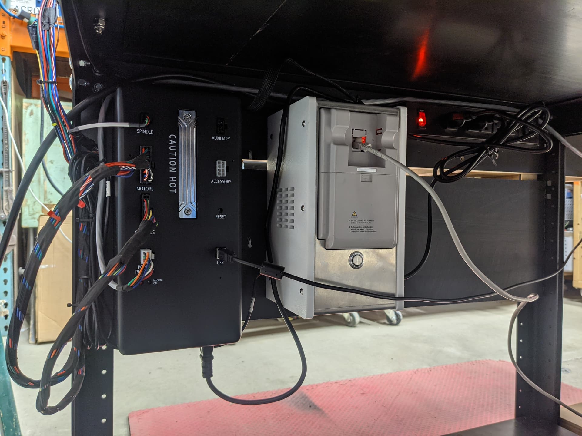
Now you should just have to put some ferrules on the new end of the wires and reconnect correctly to the VFD, and assembly and mount the box where you have planned. This is how it looks under my table as of now.
3 Likes
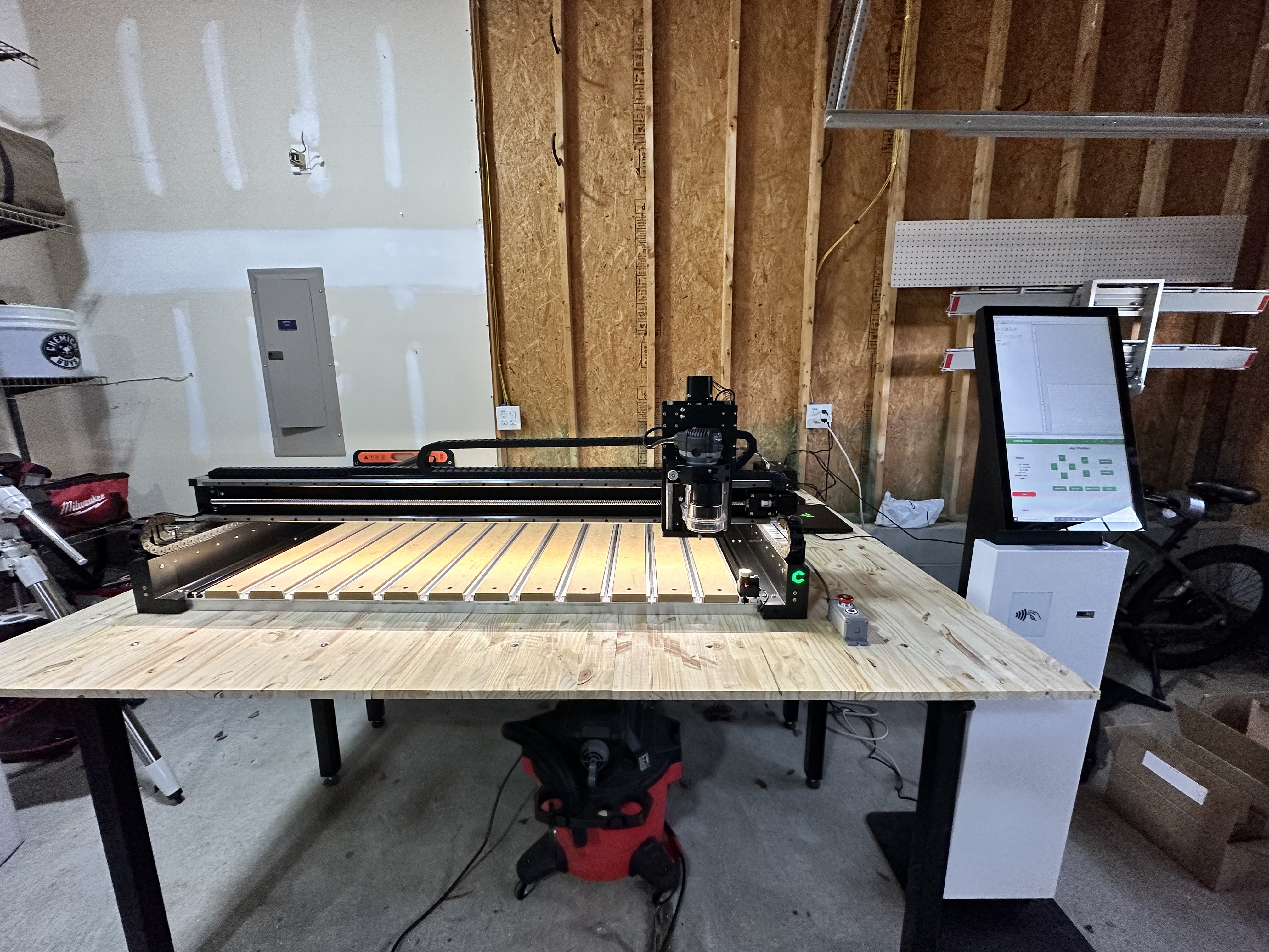
@Hivetyrant what’s going on with that controller stand? Now I feel like I need that. ![]()
3 Likes
It’s pretty great!
It’s a touch screen kiosk designed for industrial sites. I upgraded the internals and use the RFID scanner and barcode scanner for home automation stuff mostly.
3 Likes
I just noticed in your introduction to the 5 Pro, “The table T-slot spacing is now 4.04”, instead of 100mm.” Since my 3XXL has been humming along without any adjustments since I set it down about 4 years ago, I haven’t paid attention to details of the new machine beds.
There must be some reason for this not to be a simple round number as in “4.0” inches.
It comes up in my situation, because I’ve been building fixturing on 2.0 inch spacings that fit my original 3XXL spoilboard. The difference for me is a 12 inch fixture has mounting holes spaced at 10.0 inches which would be off available centers by nearly +/- 2 inches.
( 4.04 * 2 = 8.08; 10 - 8.08 = 1.92 or 4.04 * 3 = 12.12; 12.12 - 10 = 2.12)
I understand that there isn’t anything to be done (because you folks are always stuck between a rock and a hard place), but the thinking process would be entertaining since the work involved with adjusting fixturing designs is part of my decision making process.
I’m not sure how we ended up specifically at 4.04" but the driving factor was how to get a 48" wide span, get MDF over the majority of it, make that MDF fully machinable, leave clamping around the edge, but not grow the Y extrusions wider to fill any gaps.
Everything was going to be a compromise in some way.
3 Likes
Ok, its obvious that multiplying by 4.04" and 2.0" are very similar operations ![]() , but the granularity between the two gets in the way when previously designed fixturing is involved.
, but the granularity between the two gets in the way when previously designed fixturing is involved.
But, so what!? The whole machine is different! And better! (Now if I can just get someone to buy my old 3XXL … (![]() not really.)
not really.)
1 Like
Perhaps it is just angle…but that looks like a 4x8 machine.
I used a slight wide angle lens on my phone camera. I think that is what is creating that effect since you’re not the first person (or 20th) to say that. ![]()
Come on, admit it, you got a custom 4x8 Joshoko5 Pro, didn’t you ? ![]()
3 Likes
I appreciate that you think I have sway for such things. ![]()
The 4x4 is already big for my space. ![]()
1 Like
Living in southern California, I have no idea how anyone has room for a 4x4 machine, much less a 4x8.
8 Likes
I’m fortunate in the house we found before it almost doubled in value for no reason. ![]()
It’s 24x24. Currently uninsulsted exterior walls, but I did install a ceiling and insulated it. Level-ish floor. 100 amps service to a sub panel in the garage with 2 legs of 220V. If love to run gas and water, but that’s not so likely. Behind our back taste is a good 200 yard wide easement for high tension lines… so no one behind me for noise reasons.
4 Likes
Hi there! I am new to the Carbide Community, and CNC in general. On Saturday, I received my Shapeoko 5 Pro 4 x 2 machine. I’m super excited! I’ve finished the assembly, and have been taking some notes for feedback for the Carbide 3D team to hopefully help improve the assembly process.
Anyway, I have been trying to configure the BitSetter on the 5 Pro, and I have been unable to figure it out. I’ve followed along both the YouTube Assembly video (Assembly - The Shapeoko 5 Pro - Video 8 - YouTube) as well as the Configuring BitSetter video (https://my.carbide3d.com/gswso/07/) and I keep getting stuck at the last step.
I’ve tried the same thing twice with the same result, and I’m sure I’m just doing something silly incorrectly. I have tried:
- Insert a 1/4" bit into the collet of the compact router and secure it
- Power on the machine
- Connect my MacBook Pro to the USB cable on the controller box
- Open Carbide Create
- Click “Connect to Cutter”
- Select “Initialize Machine”
- Wait for the machine to initialize and move to the back right corner
- Select “Set Zero” from the “Jog” menu and clicked “Zero All”
- Opened the “jog” controls and rapid positioned the machine to the SE corner
- Used the “jog” controls to somewhat precisely position the bit directly above the bit setter, about 2-3 mm above the BitSetter button in the Z direction
- Opened “Settings” menu
- Check the box for “Enable BitSetter” in the “Options” section of the “Settings” menu
- Click “Use Current Location” button
- Click the “OK” Button
- Click “Initialize Machine” button again
- Wait for the machine to move the spindle again to the back-right corner of the assembly, and then to the front of the machine
- Click “Resume” in the “Tool Change Required” prompt (as I have already inserted a router bit into the collet)
- Observe the machine move the spindle directly above the BitSetter, but approximately 3 inches in the Z direction above the button on the BitSetter
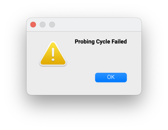
- Receive a message, “Probing Cycle Failed”
I am stuck! I would greatly appreciate someone nudging me in the right direction. I’ve attached an image from my iPhone of where the machine ends up whenever the “Probing Cycle Failed” message occurs.
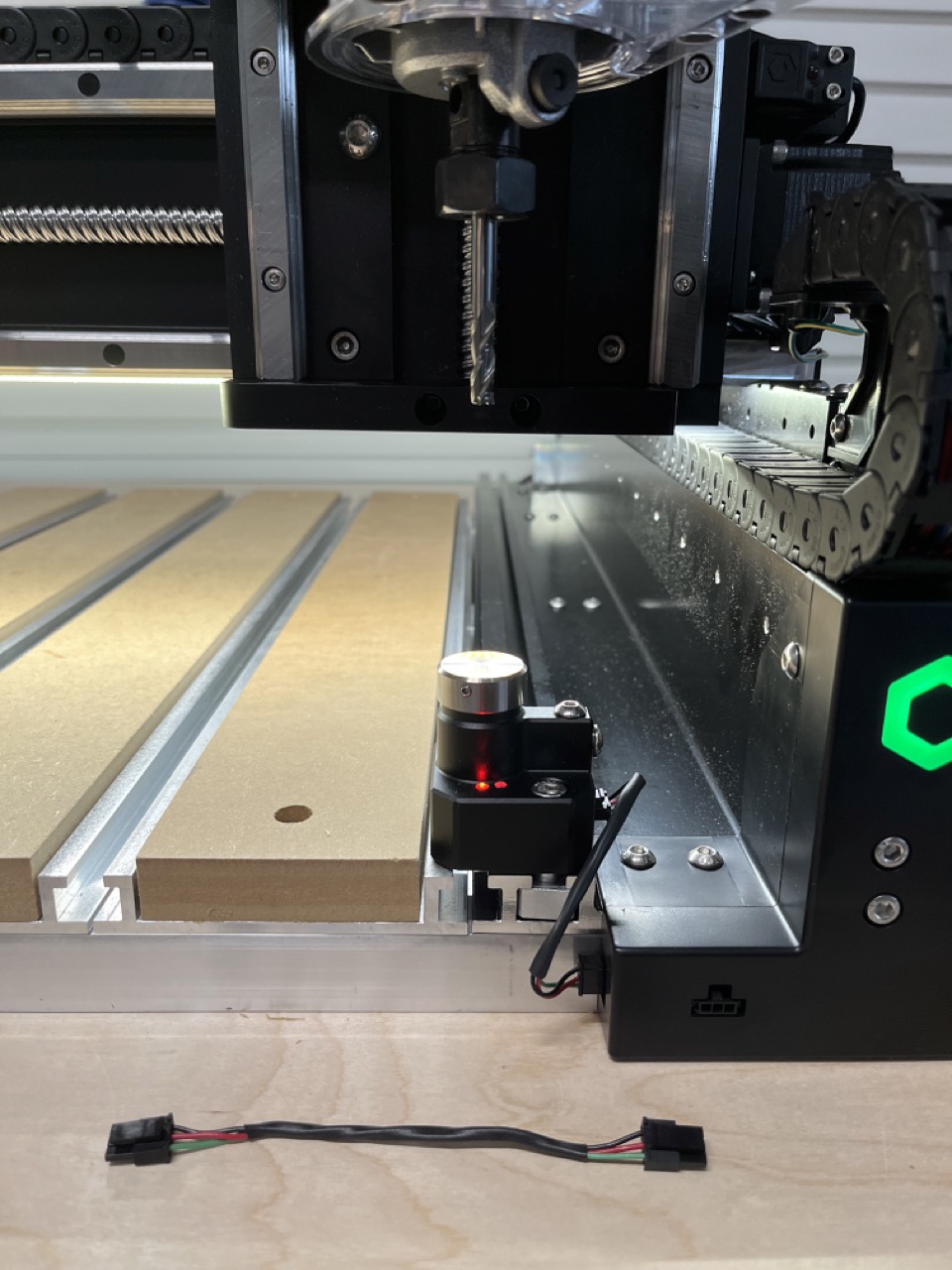
I suppose I am one of the early adopters of the new machine, and I received new wiring for the front panel extension as well as the BitSetter. I received these in a FedEx padded envelope with literally no instructions or context as to why I was receiving them but thankfully I found this forum thread which noted the issue ![]() . As you can see in the photo, the “incorrect” BitSetter extension is sitting next to the machine.
. As you can see in the photo, the “incorrect” BitSetter extension is sitting next to the machine.
What am I doing wrong? Thanks for any advice you can give me! I am excited to get started soon.
-Rob
Please install the new parts — they are intended to address this specific difficulty which you are having — contact us at support@carbide3d.com if you have any difficulties doing so.
1 Like