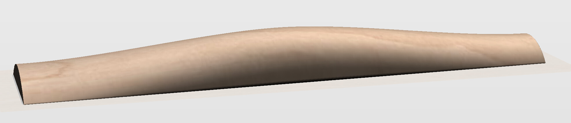
I need to mill a trapezoid shaped board with arcs in XZ and YZ planes (24 inches long, 4 inch wide at one end, 6 inch wide at the other). Each end has a max height of one inch. Half way between the ends, the max height is 2 inches. Cross sections are in the svg below. Is this possible to approximate with 3d in PRO? A mathematical approach relating the final dimensions above to the 3d modeled shape/surfaces dimensions/round angles in CC PRO would be ideal. Any takers? Thanks in advance. Bozo

Carbide Create Pro is intended more for decorative use than this sort of mechanistic 3D CAD functionality.
If you need this kind of precise control over the 3D model, you should model it in a traditional 3D CAD program such as:
and at that point you might was well use traditional 3D CAM.
If you did make the desired 3D model in a 3D CAD tool such as:
https://software.nasa.gov/software/LAR-17491-1
then it should work to export an STL and import that STL into Carbide Create Pro.
Thank you for the quick reply. Could the design be approximated? This is a decorative item, exact dimensions are not necessary. It seems like two models are all that would be necesssary, one defining the XZ surface and one defining the YZ surface. Is this correct or am I way off base? I don’t really grasp 3d modeling. Thank you. Bozo
For modeling mathematically, I just use OpenSCAD:
using the Blockly front-end:
https://www.blockscad3d.com/editor/
or, Python via:
1 Like
I’m sitting here trying to figure out how I would model it in fusion and it’s not happening with my skills.
I can place the 3 cross sections. And lift them. That’s simple. But it won’t be a curve from end to end. Will be two straight lines.
Now I need to figure this out. Thanks……
I think I might be able to do it if I draw up the wire then I can create some 3 point arcs then try and find the axis I need to revolve a shape to make the curved surface than cut out your shape from it.
1 Like
@Bozo, here is an initial try in Alibre.
loft.stl (1.1 MB)
Is it close to what you envision? I am just beginning to learn Atom (I have used SolidWorks since 1997 and though they work alike, the user interfaces are very different…) and I just drew the cross-sections you depict and lofted between them.
HTH
4 Likes
Well it cant be revolved around a single axis.
But it turns out that loft does give a curved surface
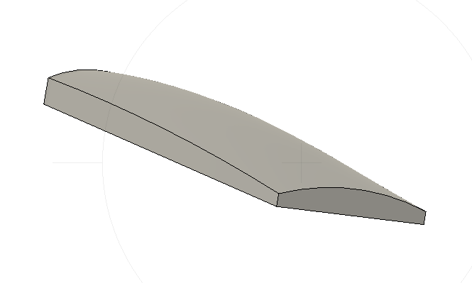
curved loft.stl (125.6 KB)
4 Likes
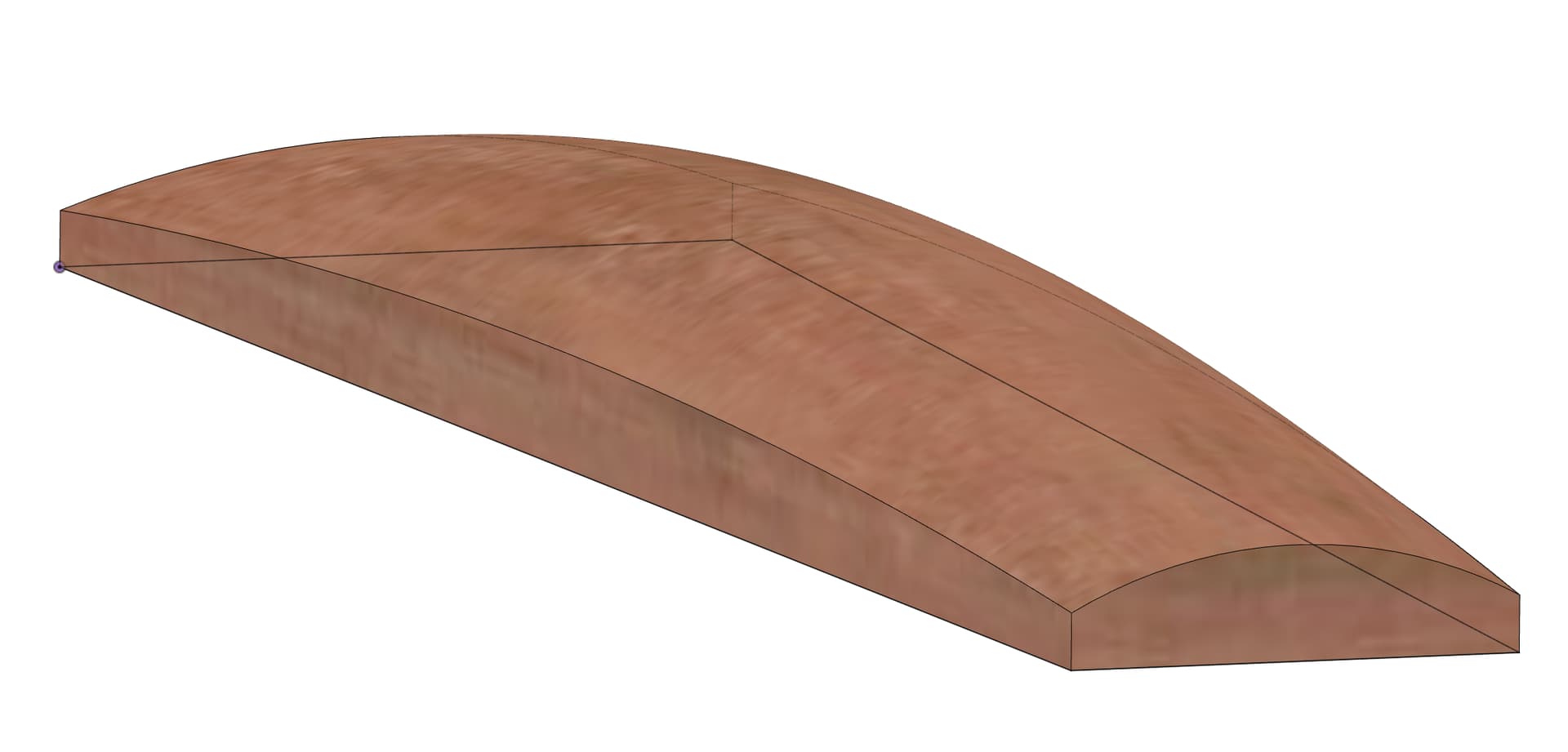
I did this in Fusion 360:
Here’s the file if you want to inspect/modify it:
Lofted.f3d.zip (78.9 KB)
I first created a sketch of the trapazoid, then a separate sketch for each of the cross-sections, located appropriately along the trapazoid, then lofted to each other.
Note the middle is 2" high while the ends are 1" high.
4 Likes
Interestingly, it works out that the base is half the total height. i.e. on the ends the curved portion is 0.5" high, and the base is 0.5" high. Same in the middle, base 1", curved portion 1".
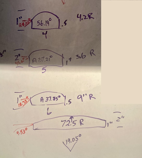
That being said, given the variable radii, and more importantly the variable chord angles, this would be difficult to model in CC. I think it’s possible, but it would require a lot of math. I’m pretty good at math, but I think even I would need a nap after figuring it out. ![]()
Here’s what I got. the Red angles being the angles you’d need to build the round component.
If someone really wants to figure this out, I will kibitz… Or to quote Sheldon, “Is this rhetorical, or did you want to do the math?” ![]()
4 Likes
Clearly, I am in the presence of greatness. Many genius IQs here. A huge thank you to all, especially Tod1d who taught me the modeled angle in CC is the angle of the tangent to the chord encompassed by the surface. Now I need some wood in the stove, coffee by my side, and study time to see what I can do with the information (after I plow snow). Cheers to all and thank you much again! Fantastic forum.
2 Likes
Ok after reading through this thread I need a handful of Advil or a bottle of Bourbon. When does the spinning stop?
2 Likes
Even if one can model this in CC Pro, I suspect you can’t create the appropriate 3D toolpaths with the core box bit, which is what you’d want to get that smooth 3D curved surface.
FWIW, there was no math in creating the Fusion 360 version. Just used the dimensions provided in the OP.
I hadn’t done a Loft before, so this was a good exercise for me to hone my F360 skills.
2 Likes
Have yourself a cup of Major Dickason’s Blend from Peet’s Coffee (now available in K-cups nationwide…I’ve drunk it since Peet’s was only 2 locations in Berlekey…). I’ve drunk it since 1981 and it’s been my CAD fuel since 1985 or so…
4 Likes
I’ve been making good use of the Gonzaga blend from Cravens coffee out of Spokane. I guess it’s time to maybe double my dose while I watch the bit spin and spew chips all over the floor and the ding dong sitting in front of the machine(me) ![]()
![]()
3 Likes
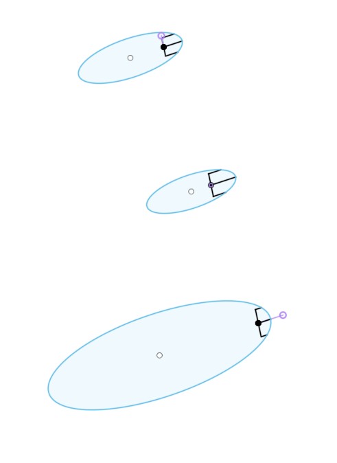
I think a close approximation is possible with PRO. The following SVG shows a single keyhole shaped model and the trapezoid to be cut 3d. A round angle of 18.92 degrees and a base of 0.5 inches should give a close approximation with this model. This is all based on the math. Now maybe I can justify a more modern computer and CC PRO to see how close I am.

1 Like
CC Pro can indeed do this as a 3D model if you model it as, say, an STL (a type of 3D solid). CC won’t do that modeling for you but you could do it in Blender (free) if you’re willing to climb a learning curve.
I’m not familiar with Fusion 360 but if it can output STL’s the file Smorgasbord created would be of use.
Interesting shape, similar to the problem of modeling a fretboard except for the additional curve along the length.
I guess it’s my turn to try it.
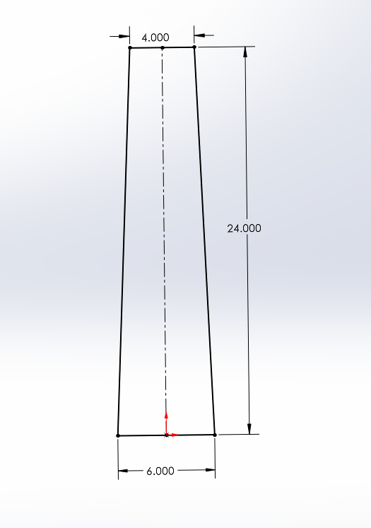
4" wide at one end, 6" wide at the other, 24" long.
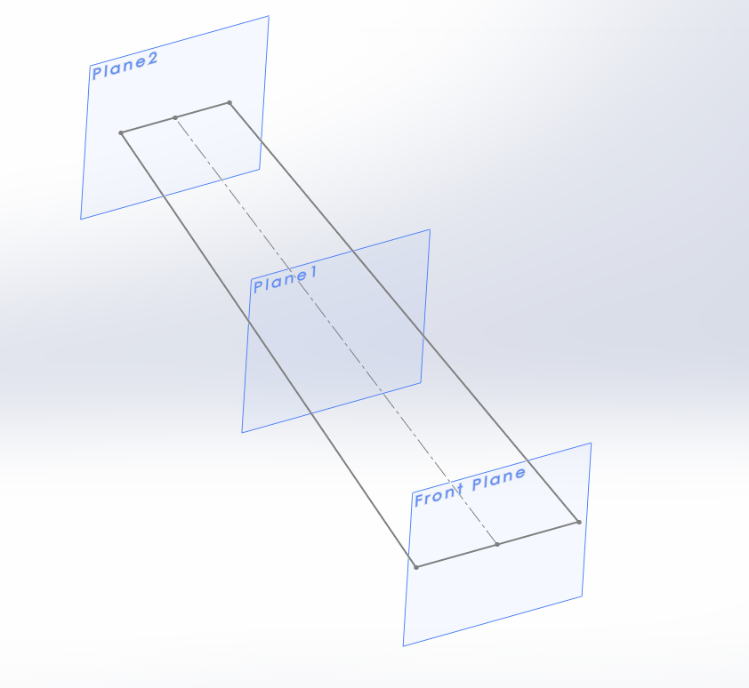
Three planes; one at 0", 12" and 24".
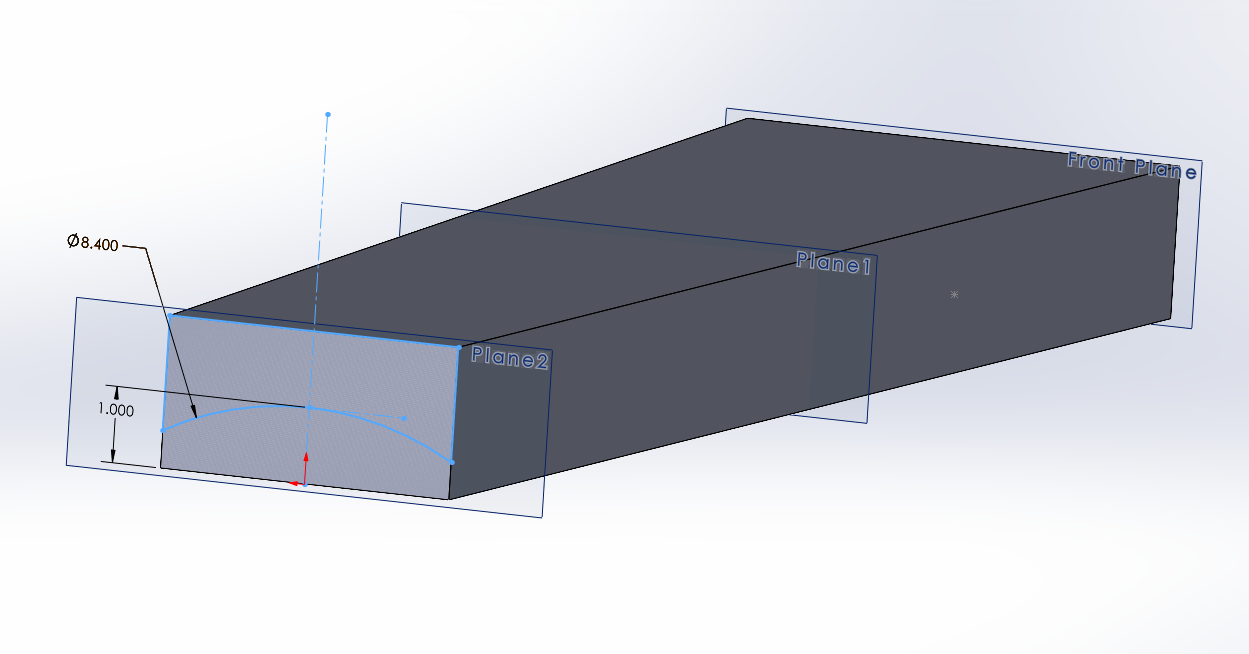
4.2" radius at the 4" wide end, with the top of the circle tangent to a line 1" above the bottom. I started with a circle, so it shows double that.
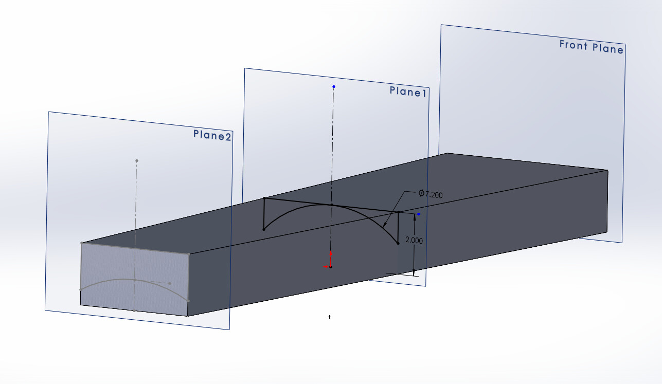
Mid-plane arc is 3.6" - 7.2" circle - with the top of the circle tangent to a line 2" above the bottom.
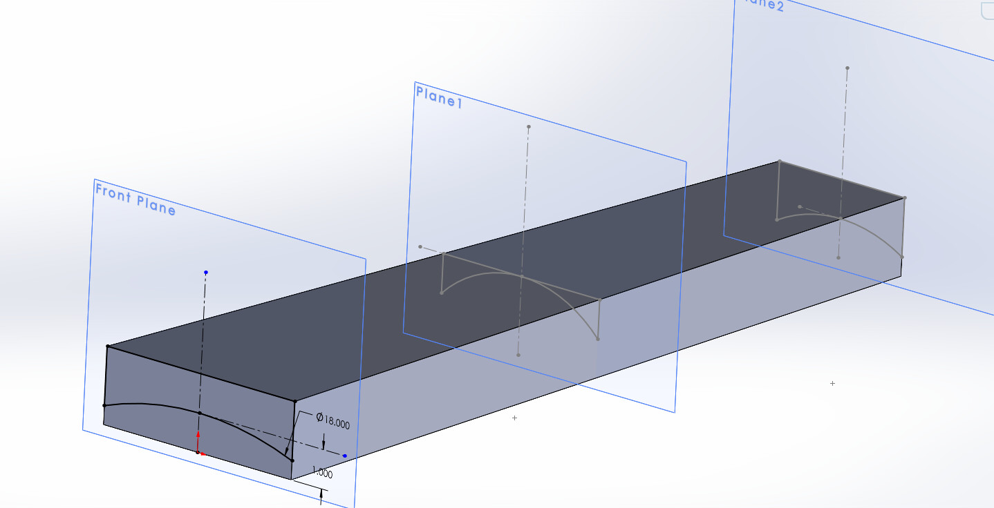
Bottom is a 9" arc - 18" circle - with the top of the circle tangent to a line 1" above the bottom.
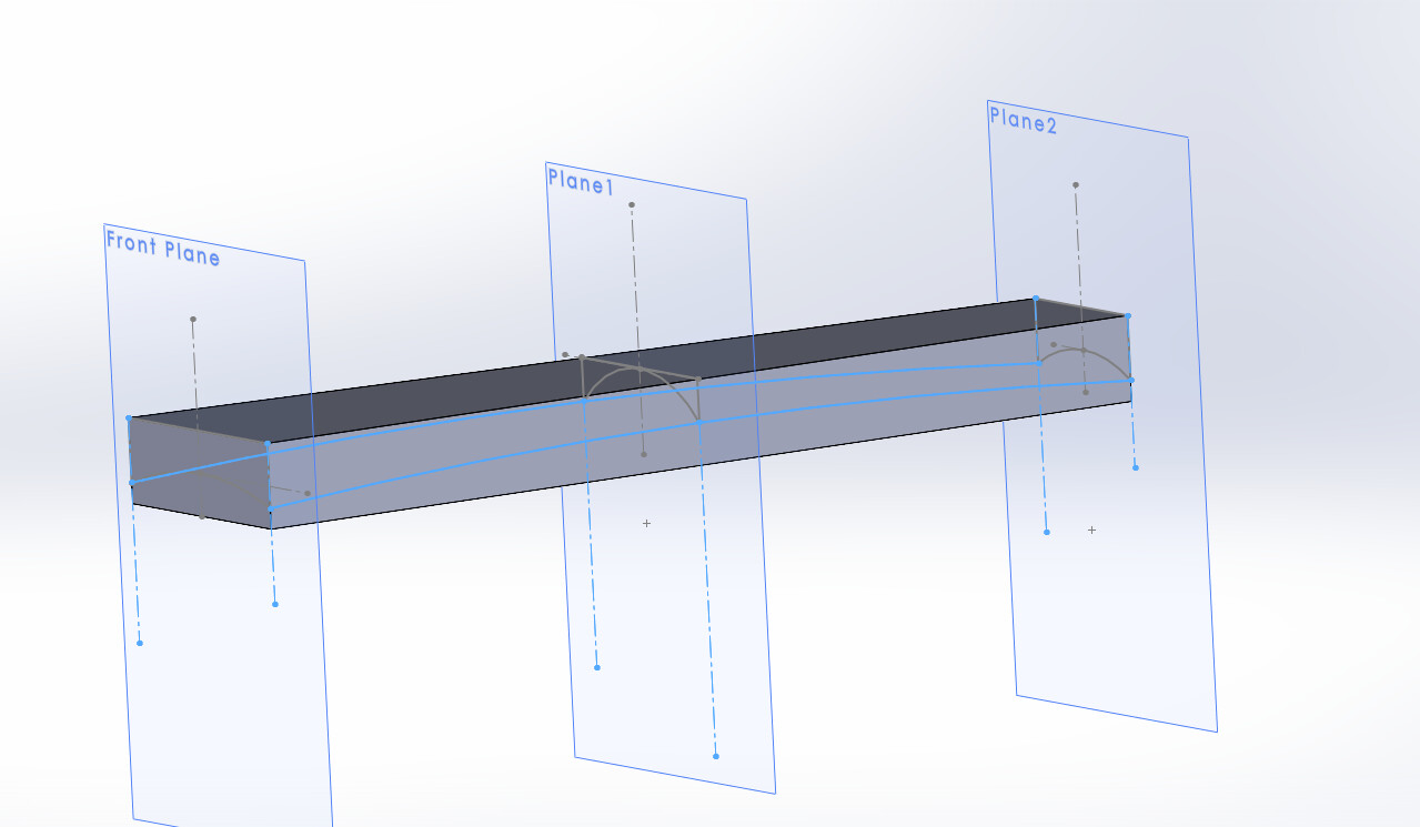
I added guide curves along each side (light blue arcs) by making a circle centered on the middle of the piece, and had all three points coincident on the circle.
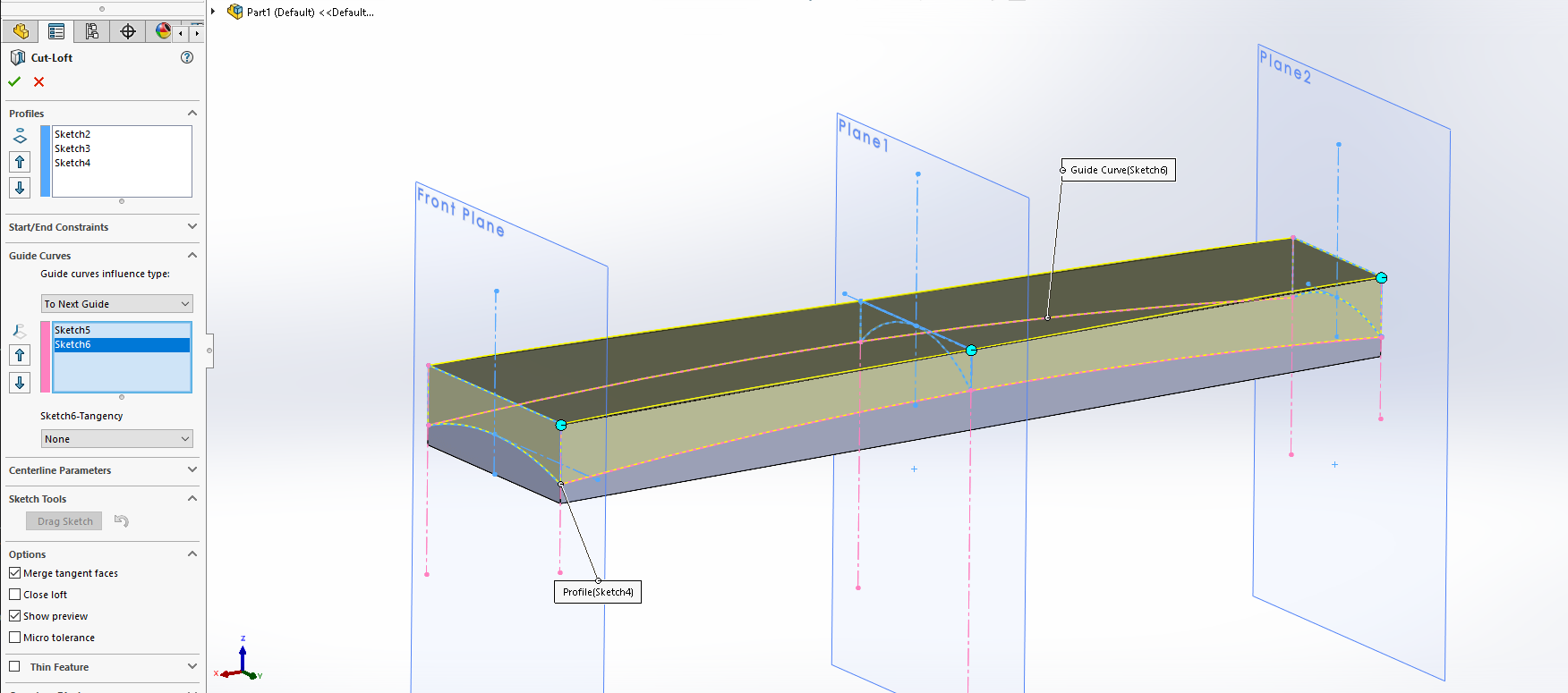
Then we do a lofted cut, and put in the three profiles, and two guide curves. I guess I could have done it as a lofted pad instead of a lofted cut, but potato potato. . .
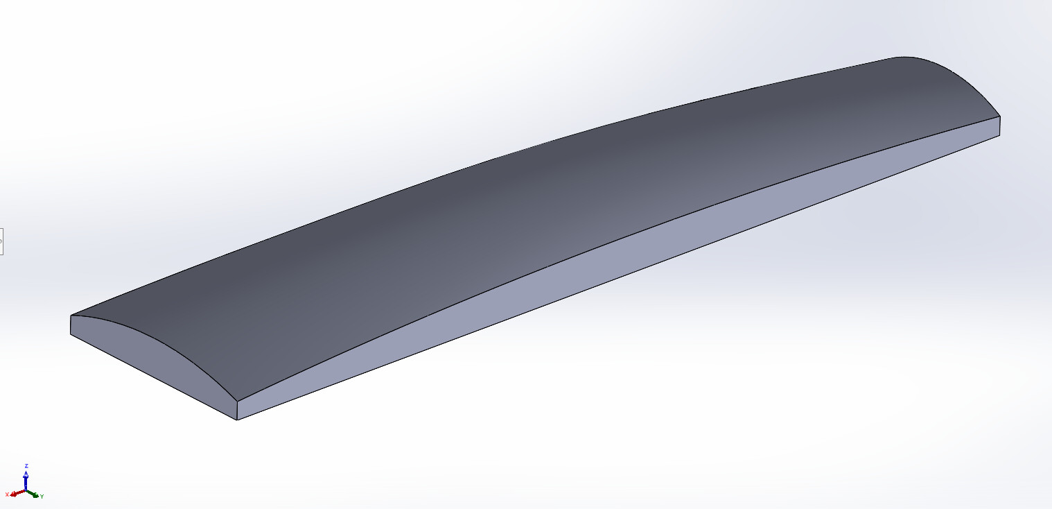
And here we are.
Bozo-T-Clowninator.STL (102.8 KB)
7 Likes
In CATIA the function is called “Multi-Section Solid”.
In SolidWorks, it’s called “Loft”
It is when you extrude a 3D solid, starting with one 2D drawing and extrude it towards another 2D drawing while it gradually changes shape from one profile to the other.
If you do not use “guide curves”, it will have sharp transitions if you have more than two 2D sketches. The guide curves dictate how the shape transitions from one sketch shape to the other.
I am not sure what Fusion calls the function, but that should be enough to get you going in the right direction.
1 Like
MadHatter, that is perfect enough. What software did you use to generate the stl? Thank you.