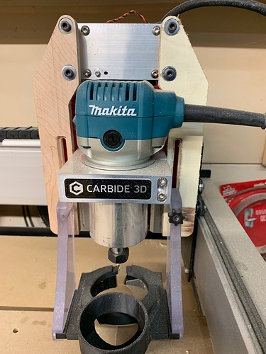
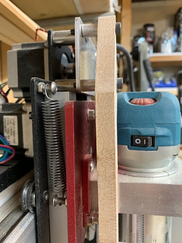
Does anyone have a Beaver Easy Tram that they either bought, and never installed, or perhaps bought and later upgraded to an HDZ? I’m not ready to jump to an HDZ, but I’m also having quite the time milling my own Easy Tram. It’s been a great learning experience so far, but I have some inventory I need to make for a show, and fussing with the tram / milling an Easy Tram is really taking up a lot of time.
I have an easy tram that came with my HDZ that I am not using, but I have no idea if it is compatible with the Carbide Z axis.
I’m not sure either, but comparing the pictures, it appears that the front plate of the Easy Tram is the same, but the larger back plate looks quite different. Thanks for the response though! Hopefully someone has one, or perhaps Mr. Beaver himself might know for certain if yours is compatible.
Nick Watters has one for sale on the shapeoko Facebook group.
I have an EasyTram but it is on my Shapeoko. I like but but just so you know, if you have a Suck-it Dust boot, you will have to modify the support as it will interfere with the operation of the EasyTram.
You know that you can download the Easytram files and make it yourself.
Hard12find: I assume you are referring to the Shapeoko and Nomad Users Group (Unofficial)? I am not a member, but just requested to join.
luc.onthego: Can you provide more detail or pictures about any Suck-It modifications? I know that I can make it myself. Actually my first attempt was how I realized that my machine was so far out of cal. I’m in a little bit of a time crunch to get some product made for an upcoming show, I’m not sure if I will be successful with another attempt after calibrating my XXL, and I’m not ready to try anodizing. In this case, I’d rather pay a few bucks and get a quality product (as Mr. Beaver always makes).
In order to adapt the Suck-it Dust boot, I had to modify the design of the Z sensor plate at the top to make it wider, add a spacer to clear the adjustment eccentric screws and router and redesign the arms so the Suck-it boot would fit the wider arms.
I’m confused. Why couldn’t you just use those spacers with longer screws and keep the dust boot arms mounted at the same location, just with an additional set of spacers?
It does not fit, the router hits the top of the arms when it goes up to hit the Z sensor. You can try for yourself.
Oh, I see now. We have different dust boots, so it’s hard for me to tell. Did you have the widen the magnetic area of the dust shoe / is the distance between the clear support arms further apart than before? Also, did you have to adjust the dust shoe to fit different front to back / get it to still be centered under the router because you shimmed everything out?
That write-up has my design for custom arms (to replace the stock black arms) and so on (including my custom SmokeSucker to add Suckit-compatible laser smoke extraction).
The custom arms clear the EasyTram hardware and give wider clearance for the router at top of Z travel while not reducing X travel (even in my case with swapped Y plates). Also required are spacers to mount the new custom arms and spacers to widen the boot’s reach (unscrew the magnetic sliders, add the spacers, and screw it back together with slightly longer #6-32 3/4" socket head cap screws). There’s enough adjustment in the magnetic sliders to account for the front/back positioning.
Thanks for the details (and the files in your link). I don’t have a 3D printer (yet). Could you specify what thickness you added between the the Z sensor plate and your new arms? I’m trying to order the parts I need now because I work 3 hours away from my XXL during the week and only get to work on it and also try to make product for shows on the weekends. Anything I can do ahead of time in design or parts ordering helps save precious weekend time with the machine.
btw, for anyone following…I did claim the Easy Tram from the FB group posting. So now I just need to install it and get the dust boot to fit up as well.
I ended up using 6mm spacers between the Z switch plate and the arms.
As for the 3D printed parts, I do have a 3D printer, so it was natural to make bespoke parts that made everything look stock. If I didn’t have one, I likely would’ve just gone the field-expedient route and used simple stacks of washers for the arm spacers (as close to 6mm as practicable without going under).
For the 8mm spacers on each side the boot, I would likely cut them with a 1/8" endmill, just for aesthetics. They’re just rectangles with slots for the screws to pass through, no real need for tight tolerances. It would seem similarly reasonable, however, to just go with washer stacks there, too. The magnetic sliding blocks more than fill the slots on the clear mounting arms, so washer stacks sticking out would not interfere with anything. There’s a bit of wiggle room, too, so just being close to 8mm extra on each side would be sufficient. Having it look stock (or have racing stripes on the boot, if you use a different color/material for the spacers) is rather aesthetically appealing, of course. ![]()
The only “non-negotiable” parts, really, are the #6-32 3/4" socket head cap screws for the boot (to attach the magnetic sliders through the new 8mm spacers, whatever you use).
No that is what I fixed with the new arms and shims, the bit is about 1/4" off the center but well within the dust boot cutting area.
For the spacer, I used 3/8" aluminum round stock 1/2" long that I drilled out the middle.
Thanks for the info, everyone! I will probably try to just mill the spacers at the same time that I mill the new arms. I think I’ll order 1/2" acrylic on Amazon, since I like the way it looks instead of the polycarbonate.
ClayJar: Do you have a good idea about the size of bolts I’ll need to use at the Z plate? I’d rather not trust that my local Ace will have them in stock, so I’ll just order them ahead of time online if I know what to order (along with the SHCSs for the magnetic sliders). Also, just making sure I don’t need to add any more magnets or anything to get the dust boot centered under the router? I think it’s a 1-1/4" hole in the dust boot and I have a 1" carbide insert bit that needs the clearance through that hole. I would easily order some tiny magnets if you think I might need to readjust things.
I know what you mean about wanting to be sure you have the hardware you need. I ordered a pack of assorted-size M5 button head screws to know I was covered. In the end, I went with the 35mm M5 button head screws.
The magnetic sliders have quite a lot of adjustment built in thanks to the slots the #6-32 socket head cap screws. I altered my Suckit setup several times before arriving at its currently-final implementation, and all I ever needed to center the hole and spindle was to loosen the #6-32 screws and adjust the sliders forward or back. (In the final config, I ended up at what I’d basically consider zero offset, so there’s play to work with.)
Awesome! Thanks for the help. I’ll order that pack of screws. I actually just bought basically the same pack, but all of the shorter lengths last week when I was going to try to mill my own Easy Tram. I guess you can never have too many M5 BHCSs!
This topic was automatically closed 30 days after the last reply. New replies are no longer allowed.

