Hi Will
It’s a tissue box 15cm x 10cm x 4cm deep (internal). It is open because the open side goes down over the tissues and the closed side will have an oval opening of around 6cm x 7m. I will use some elm that is originally 19mm but I will sand it down probably to around 15mm. I may have a 102 somewhere but I definitely have this:
Amana Tool 51474-Z SC Spiral O Single Flute ZrN Coated Aluminum Cutting 1/8 D x 1/4 CH x 1/4 SHK x 2 Inch Long Up-Cut Router Bit withMirror Finish
That tool has a 1/4" cutting flute length:
you’ll want a narrow tool which has a cutting flute length to match, or at least be close to the stock thickness.
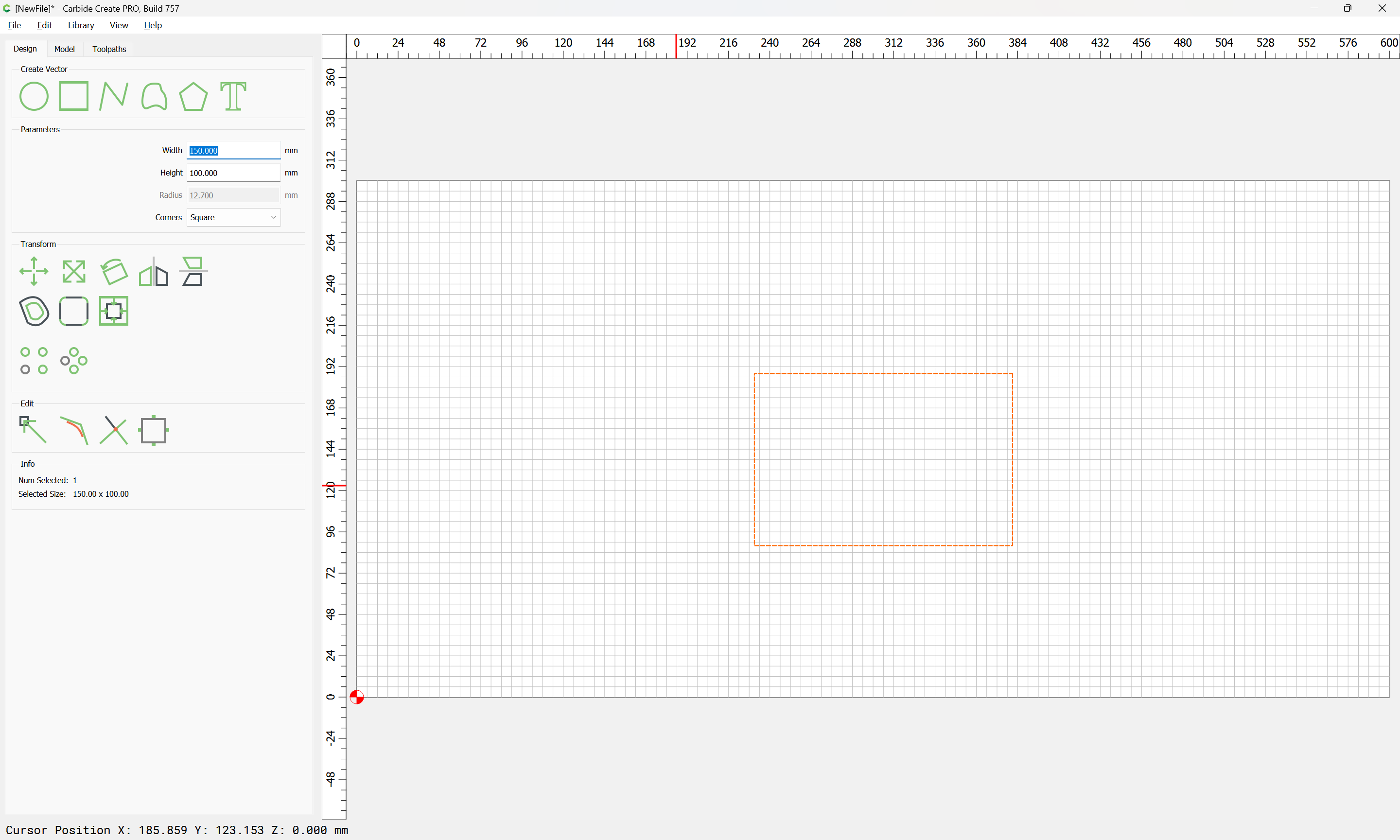
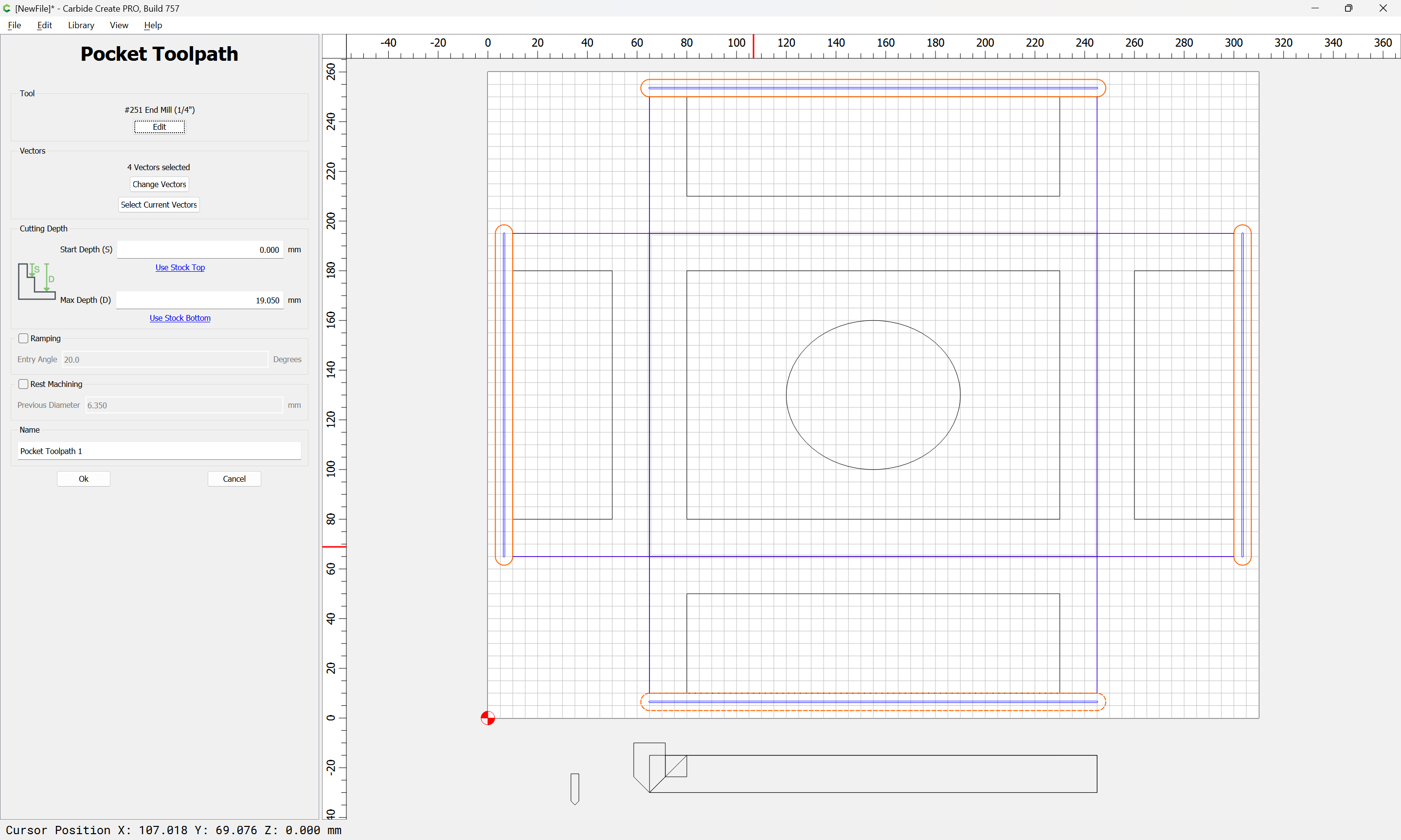
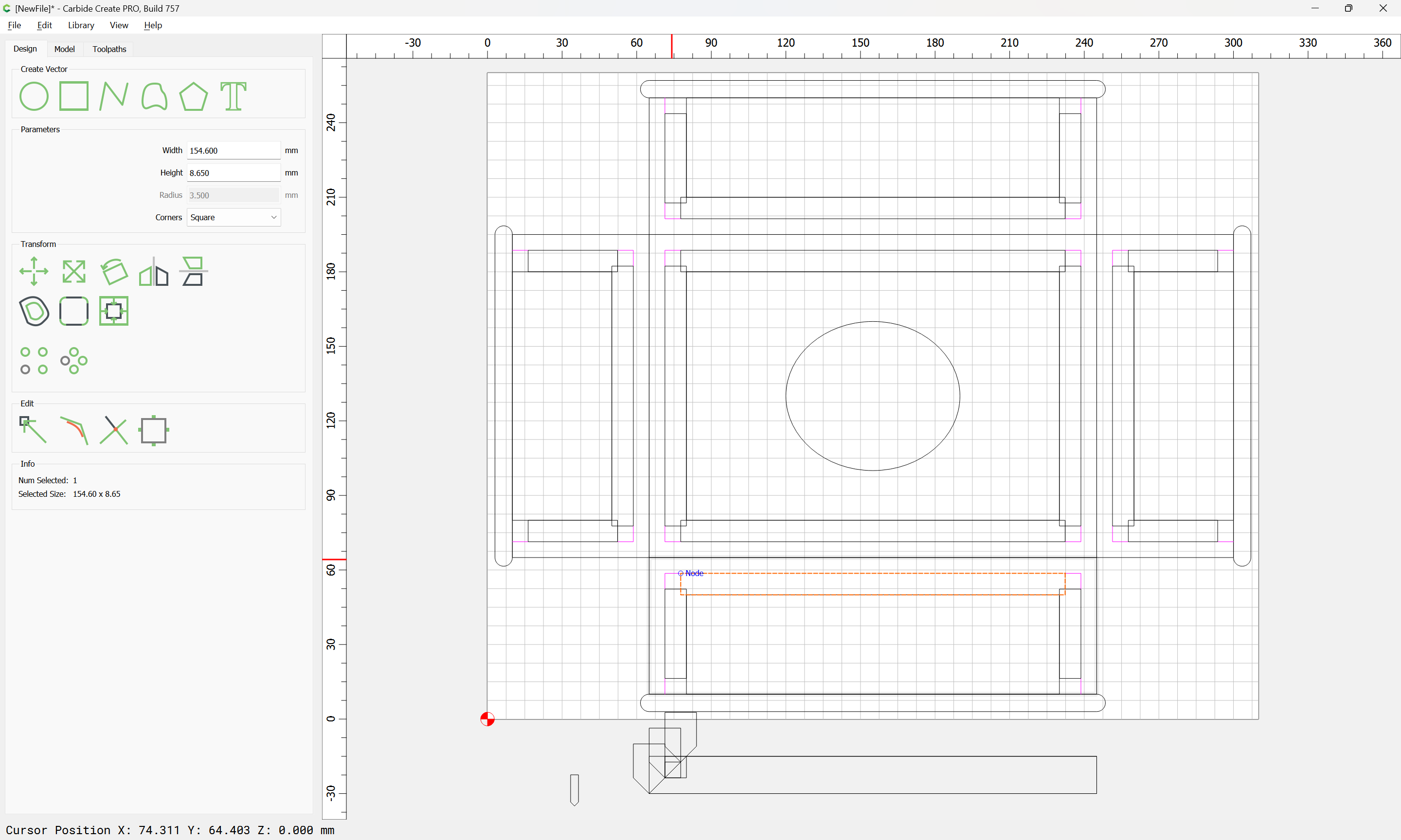
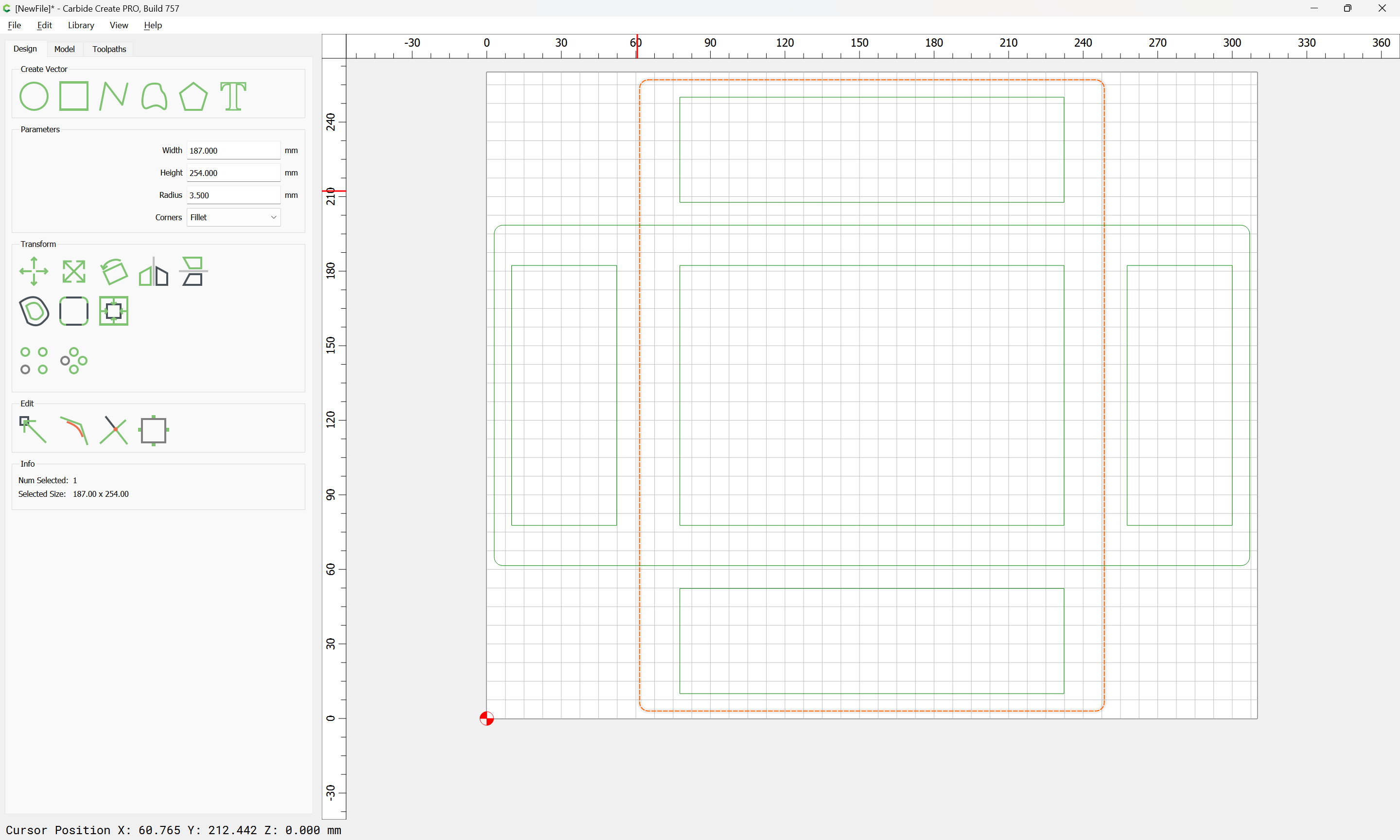
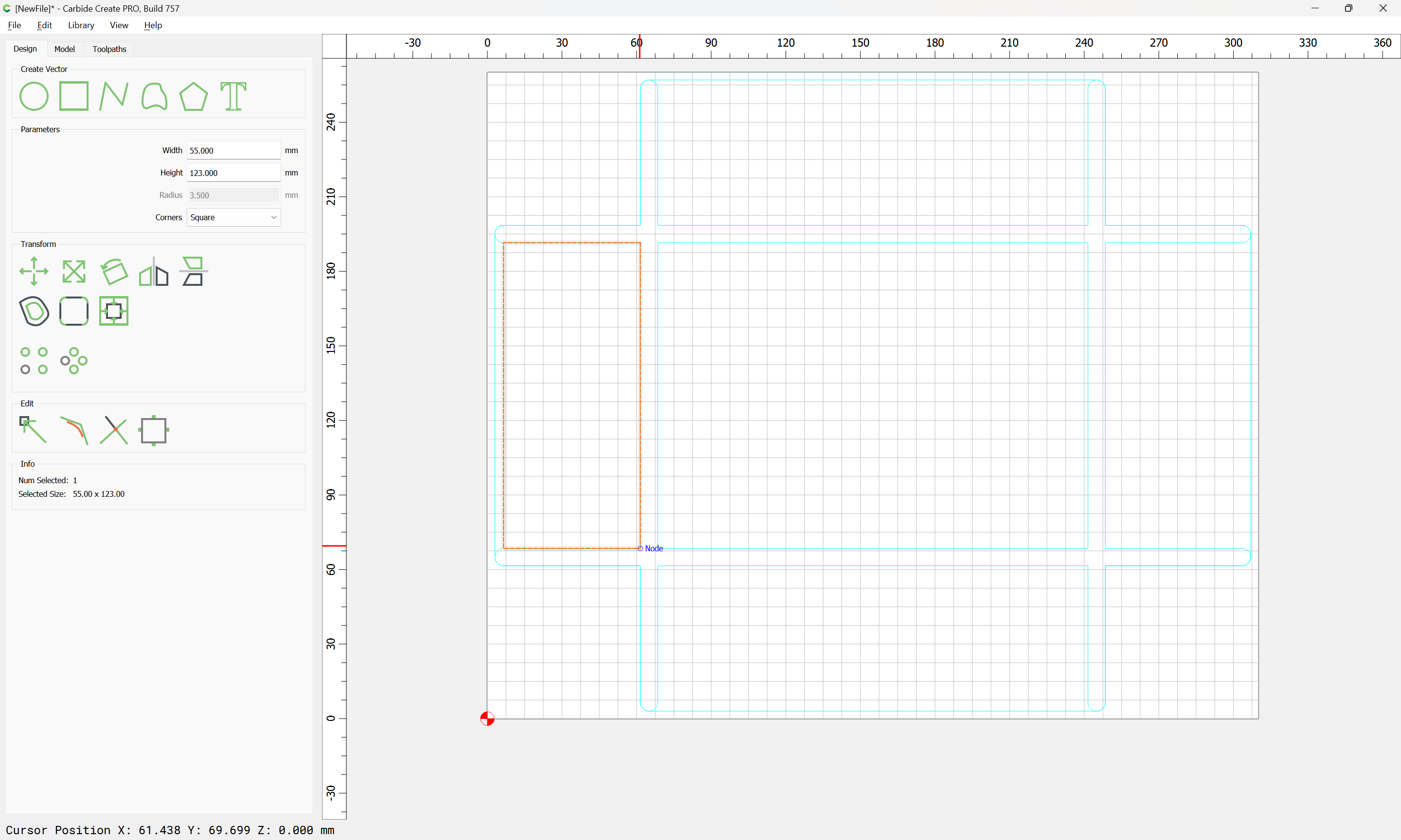
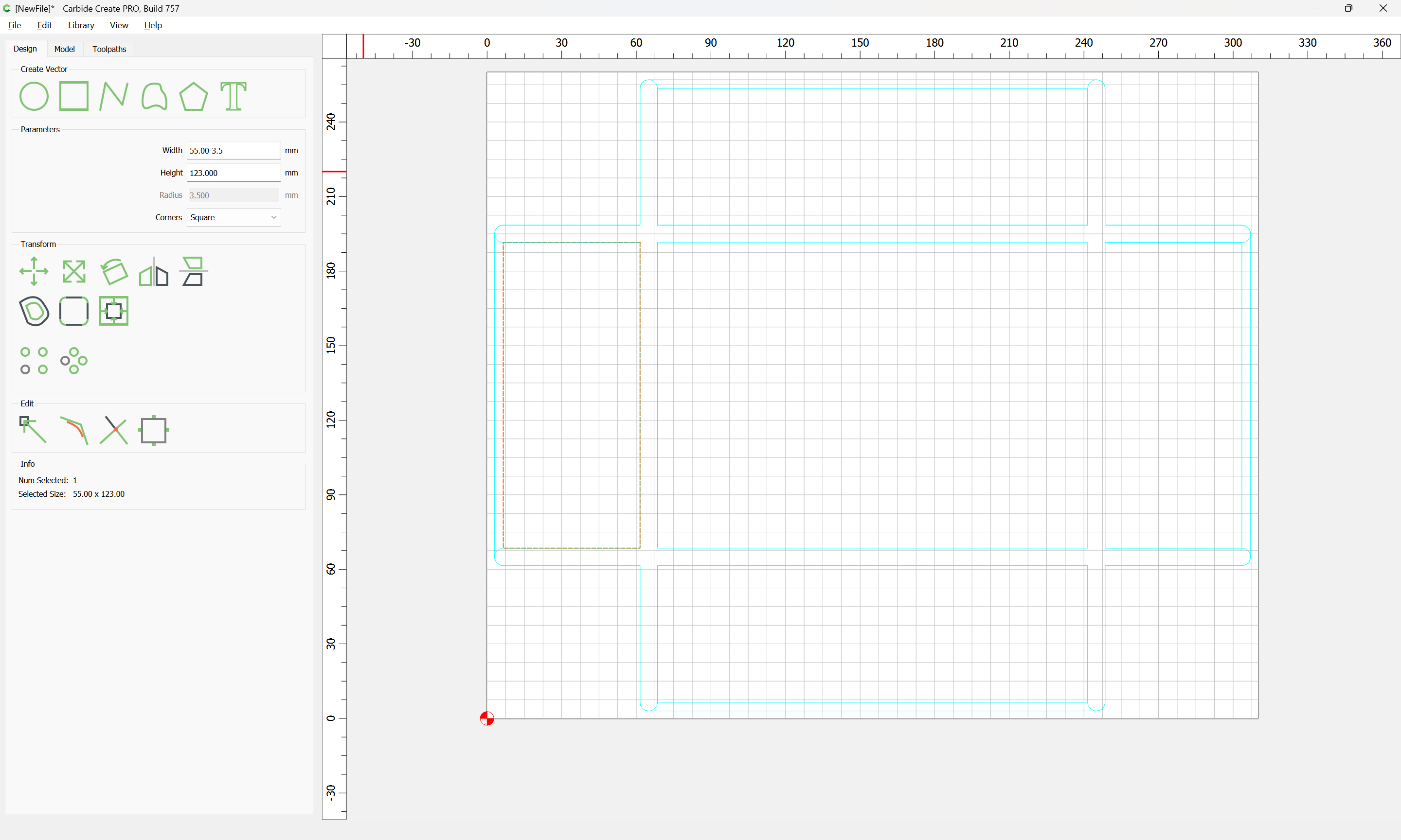
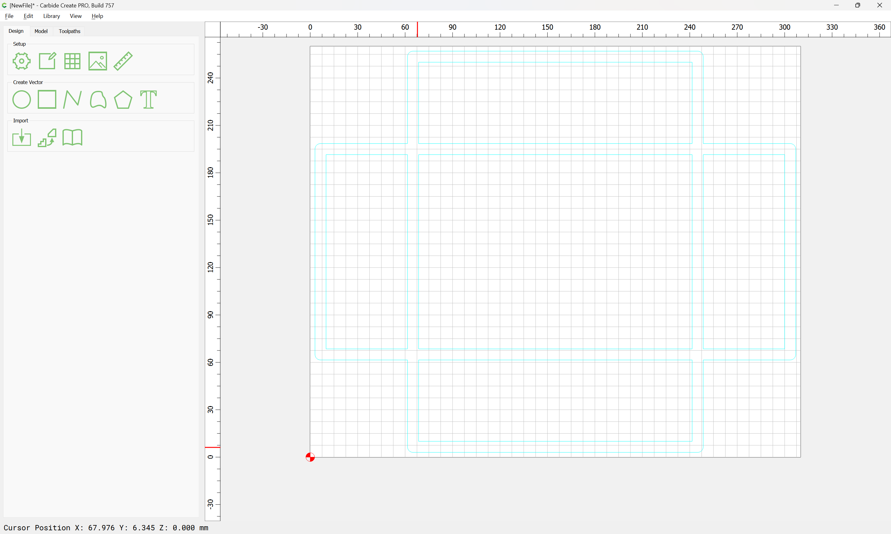
Setting this up is pretty straight-forward — first draw a rectangle for the internal dimension:
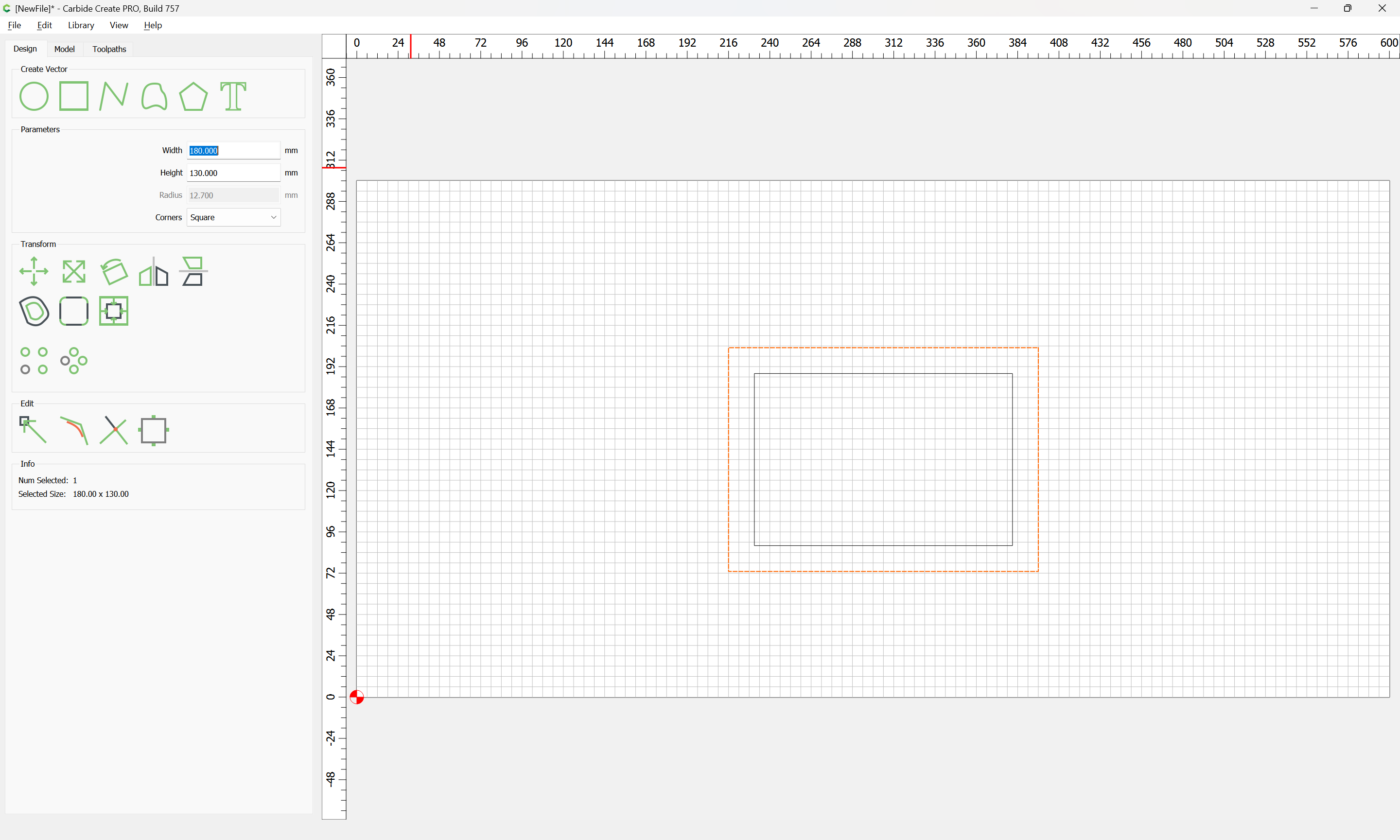
Dupe it in place and add the stock thickness all around:
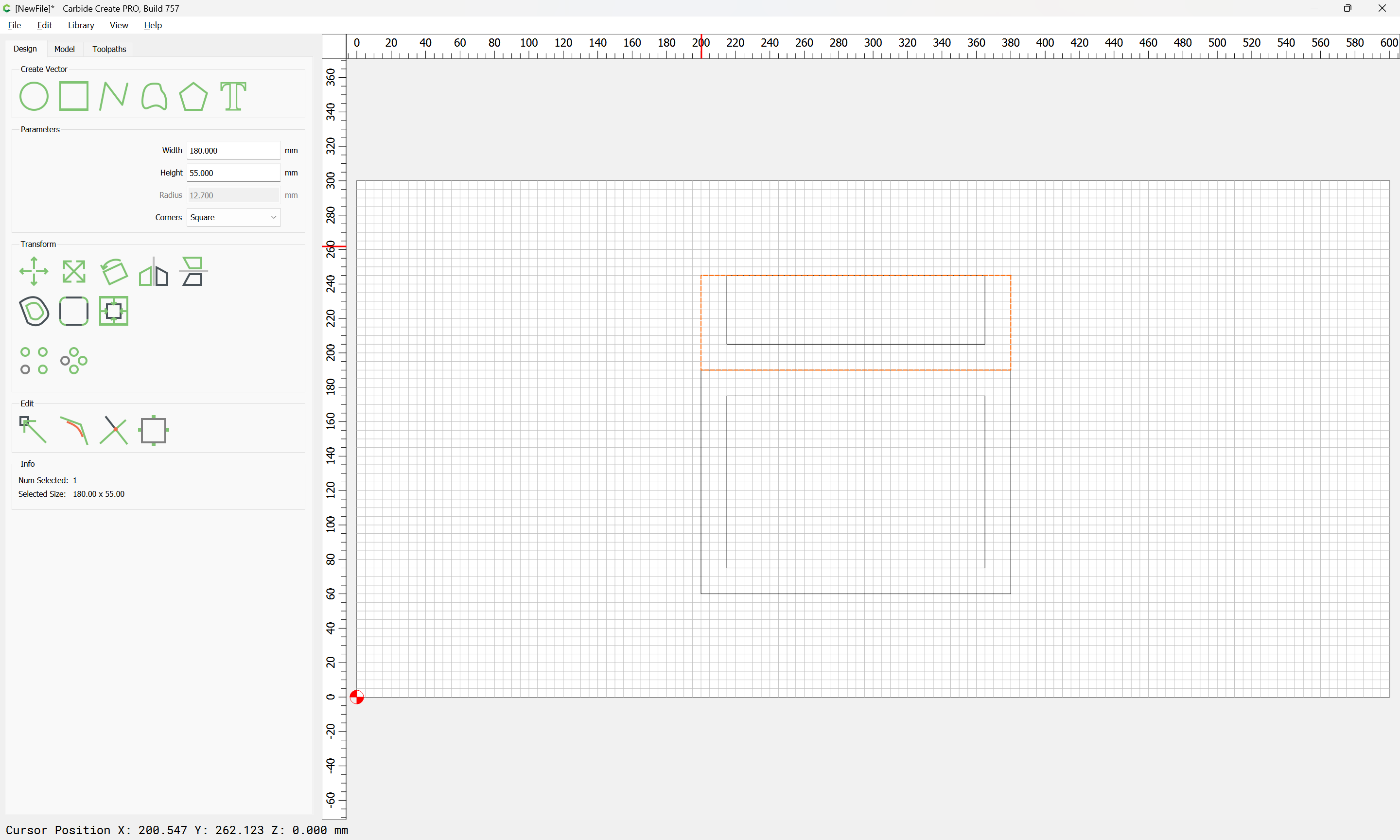
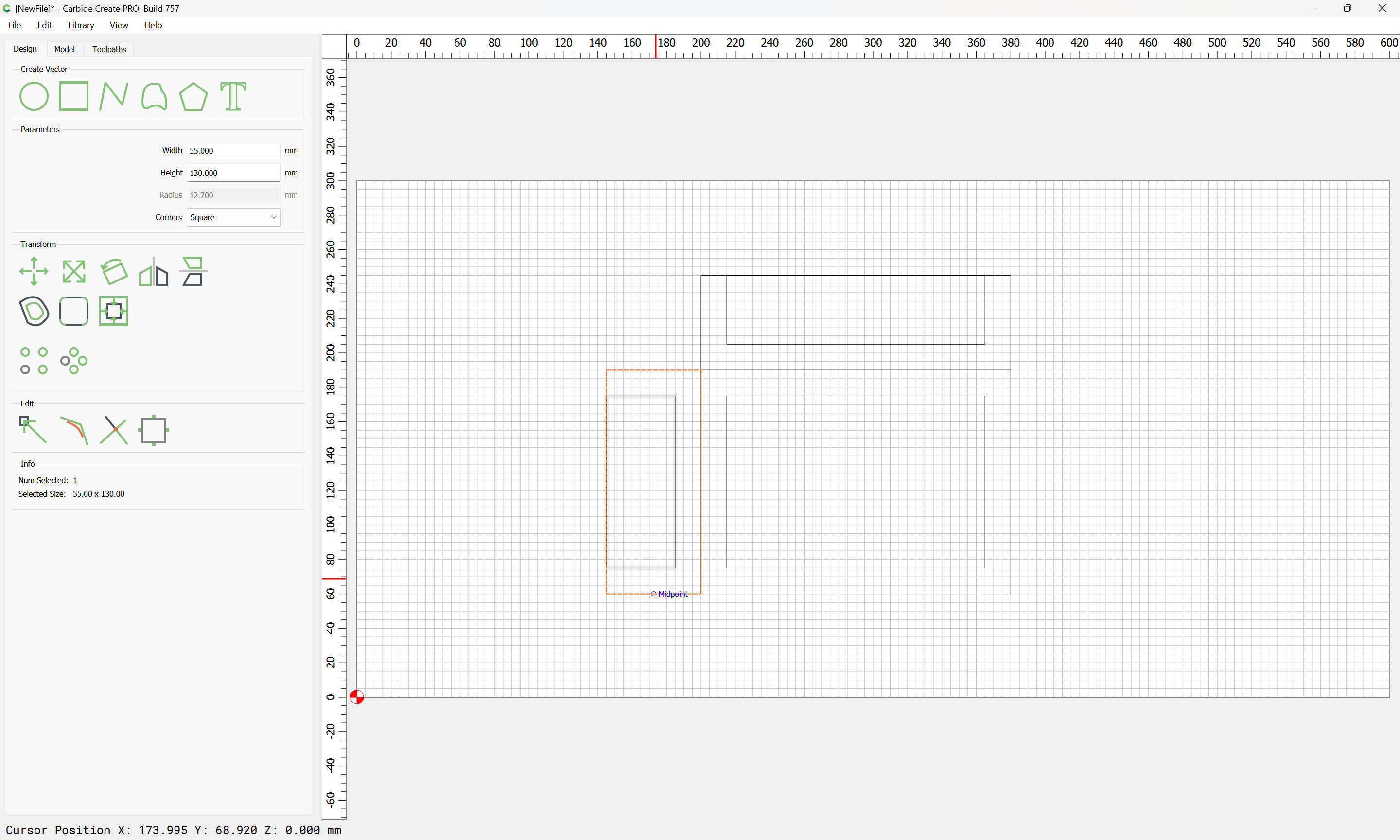
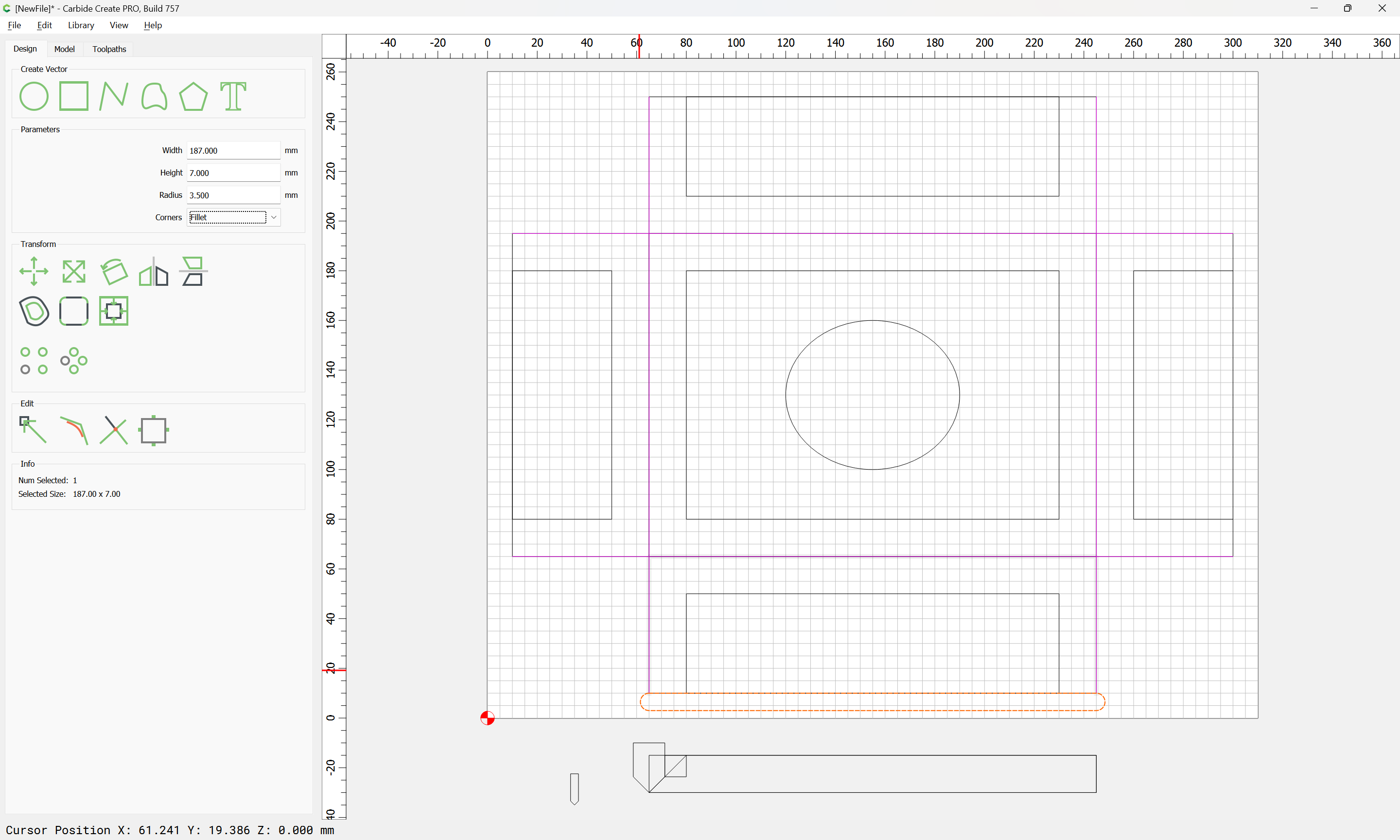
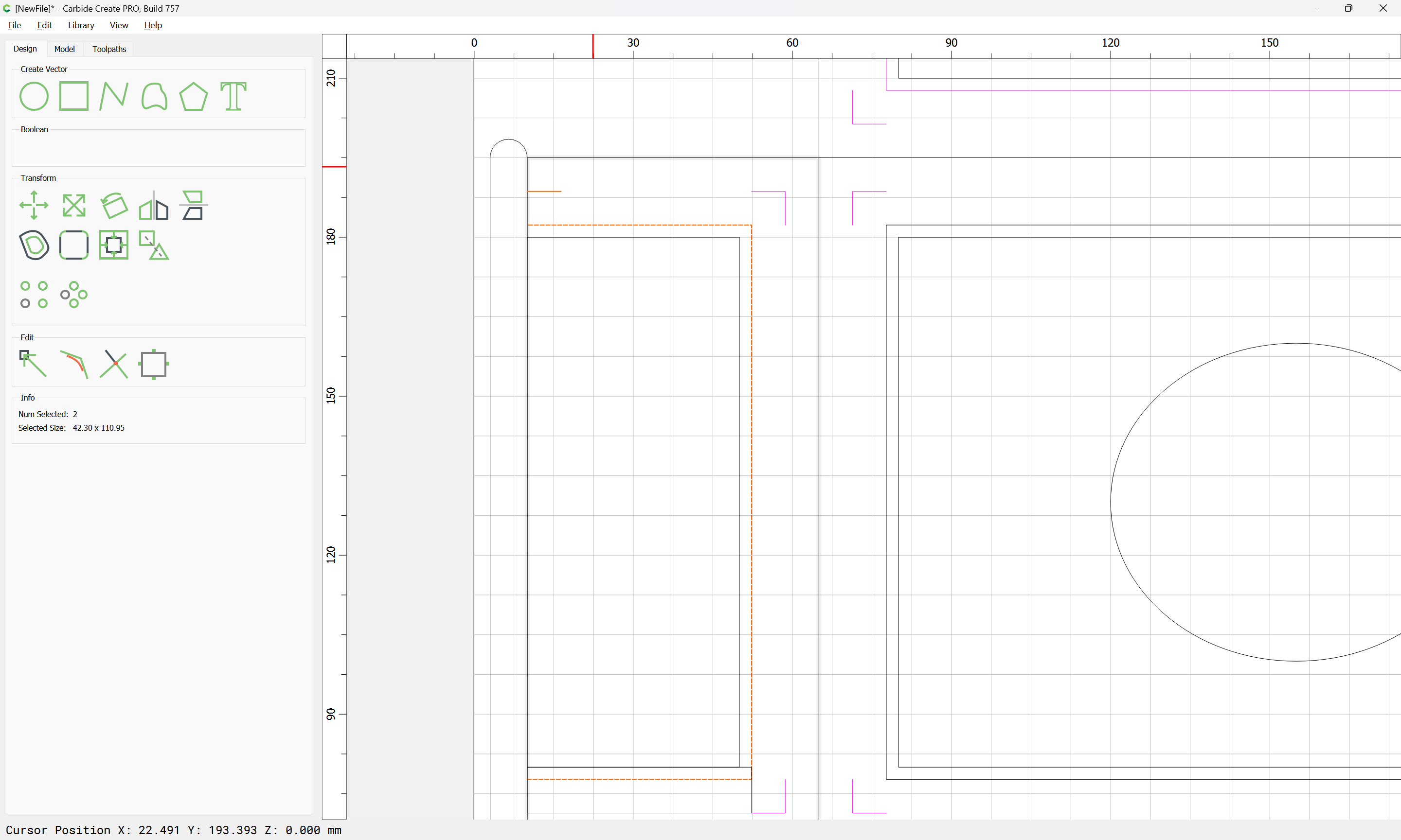
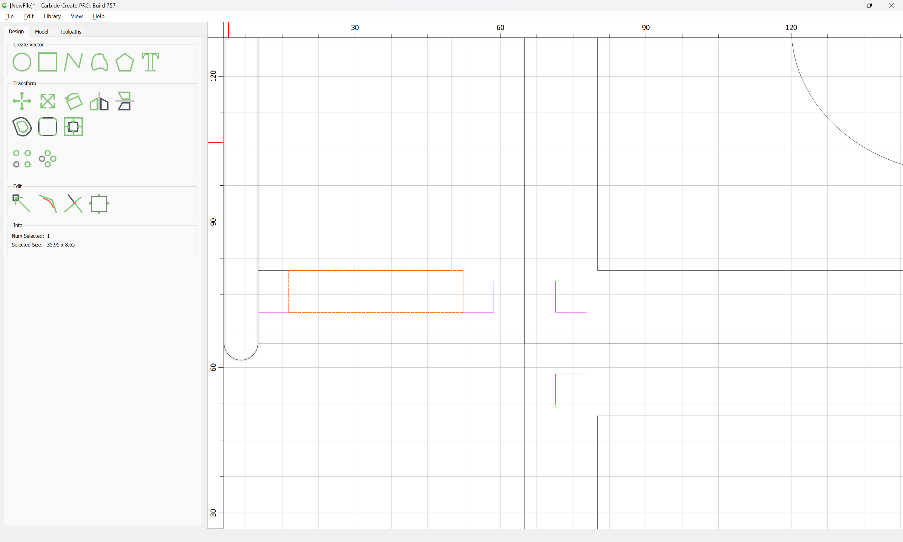
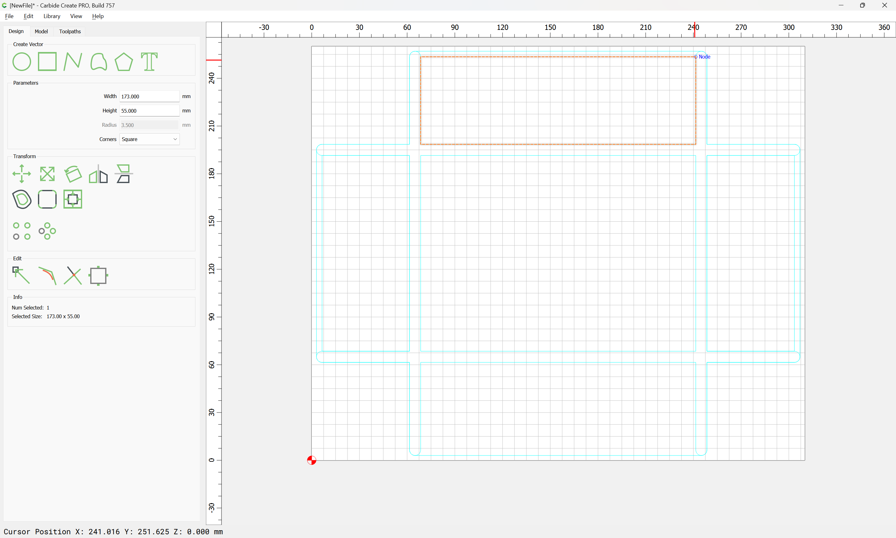
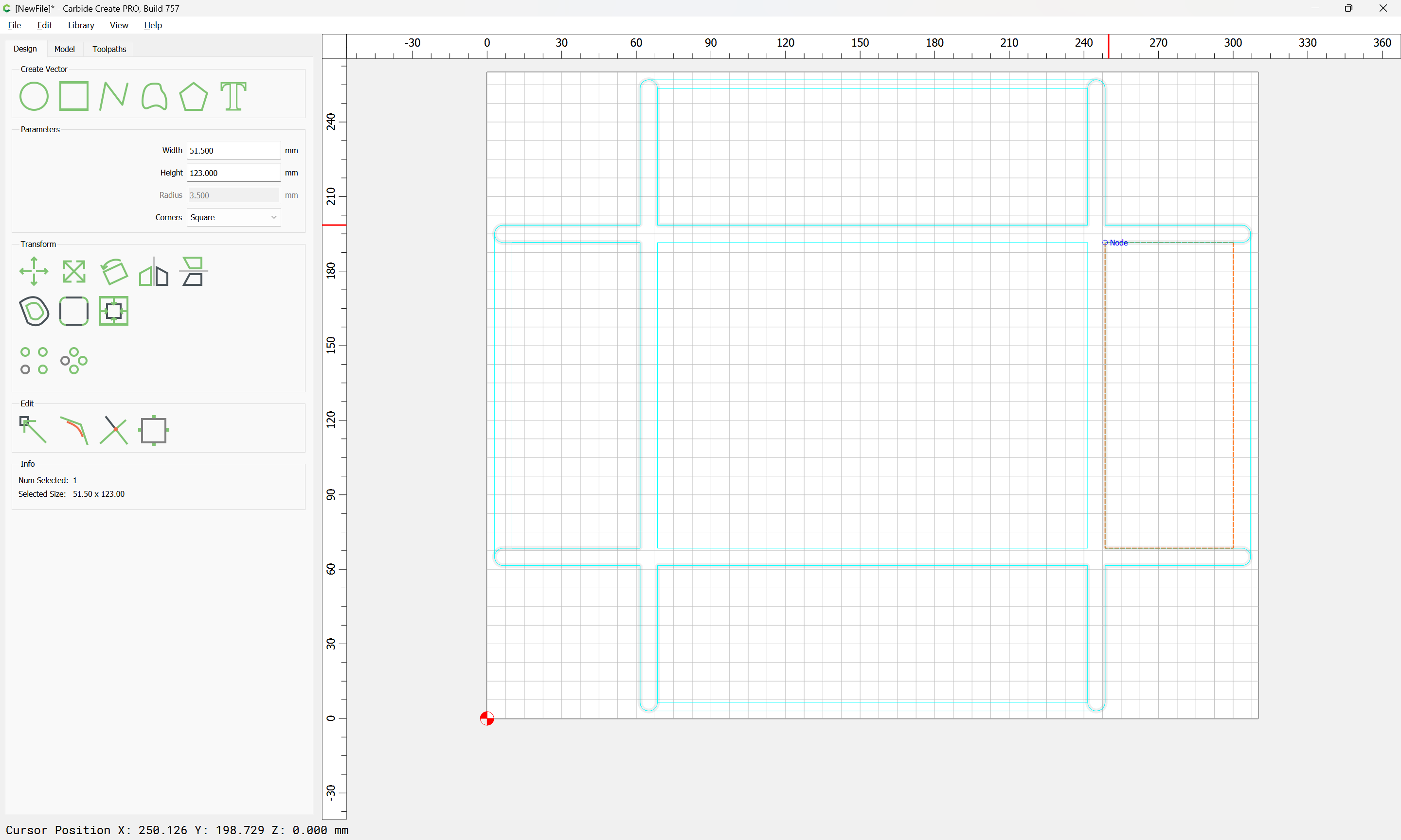
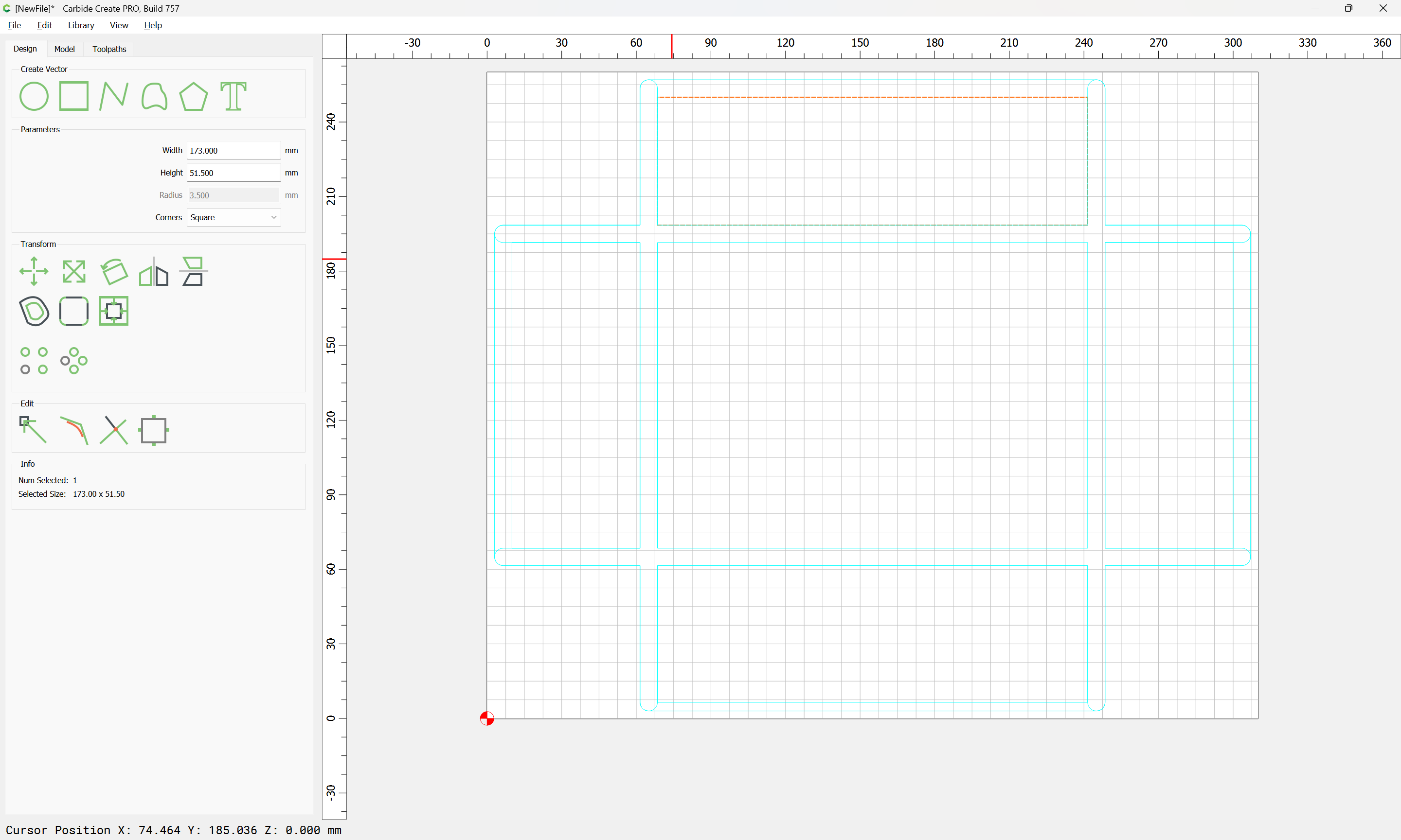
Do the same for the sides:
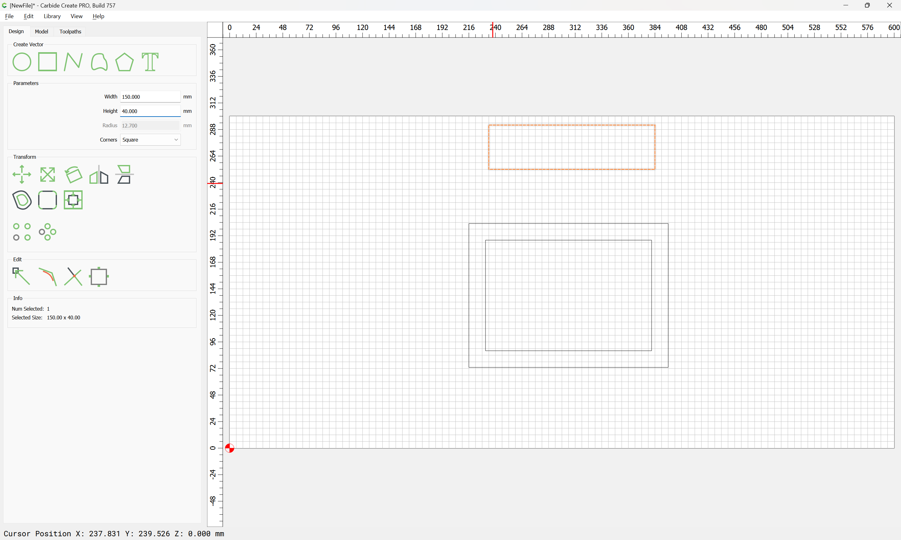
except that one only adds stock thickness once for the height:
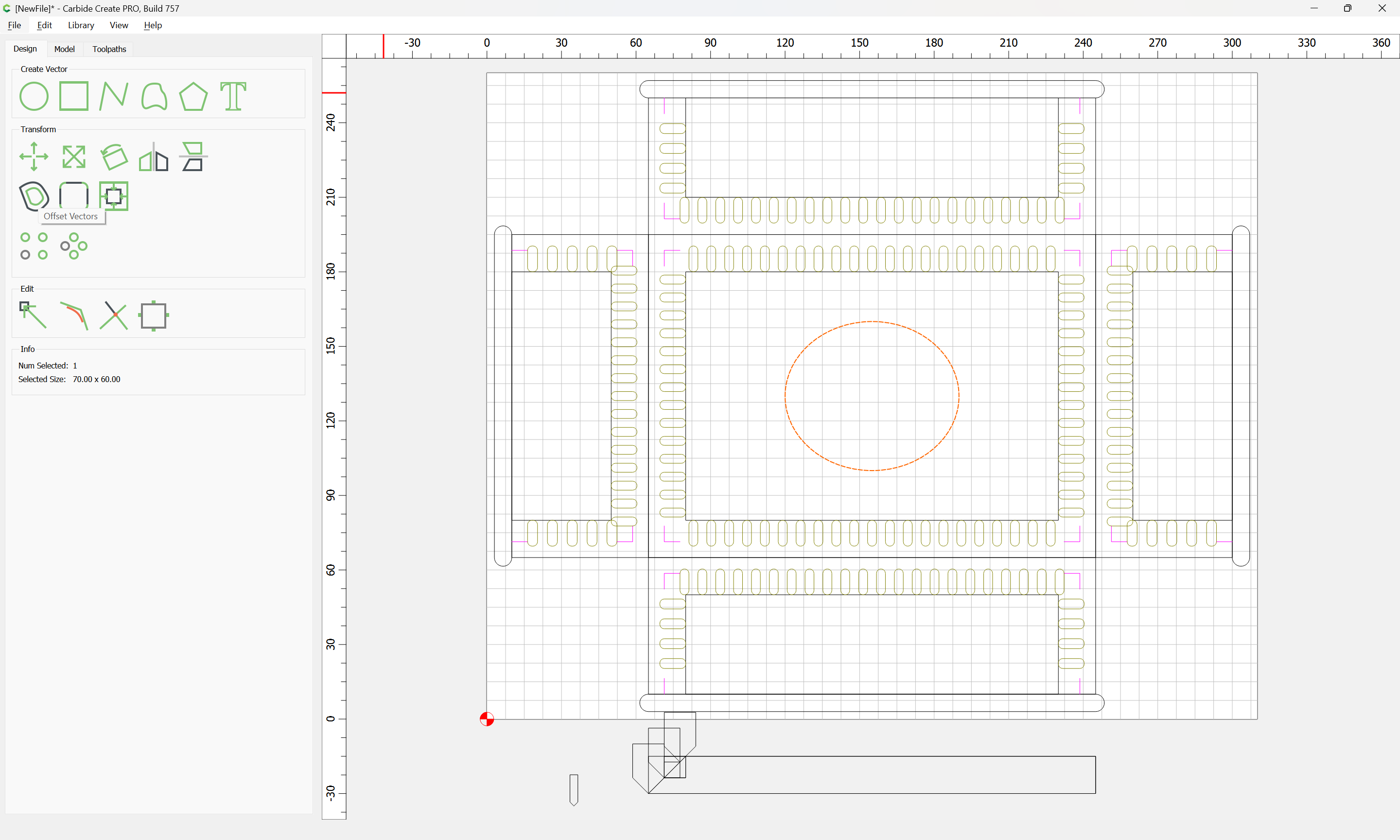
and draw in a circle for the oval:
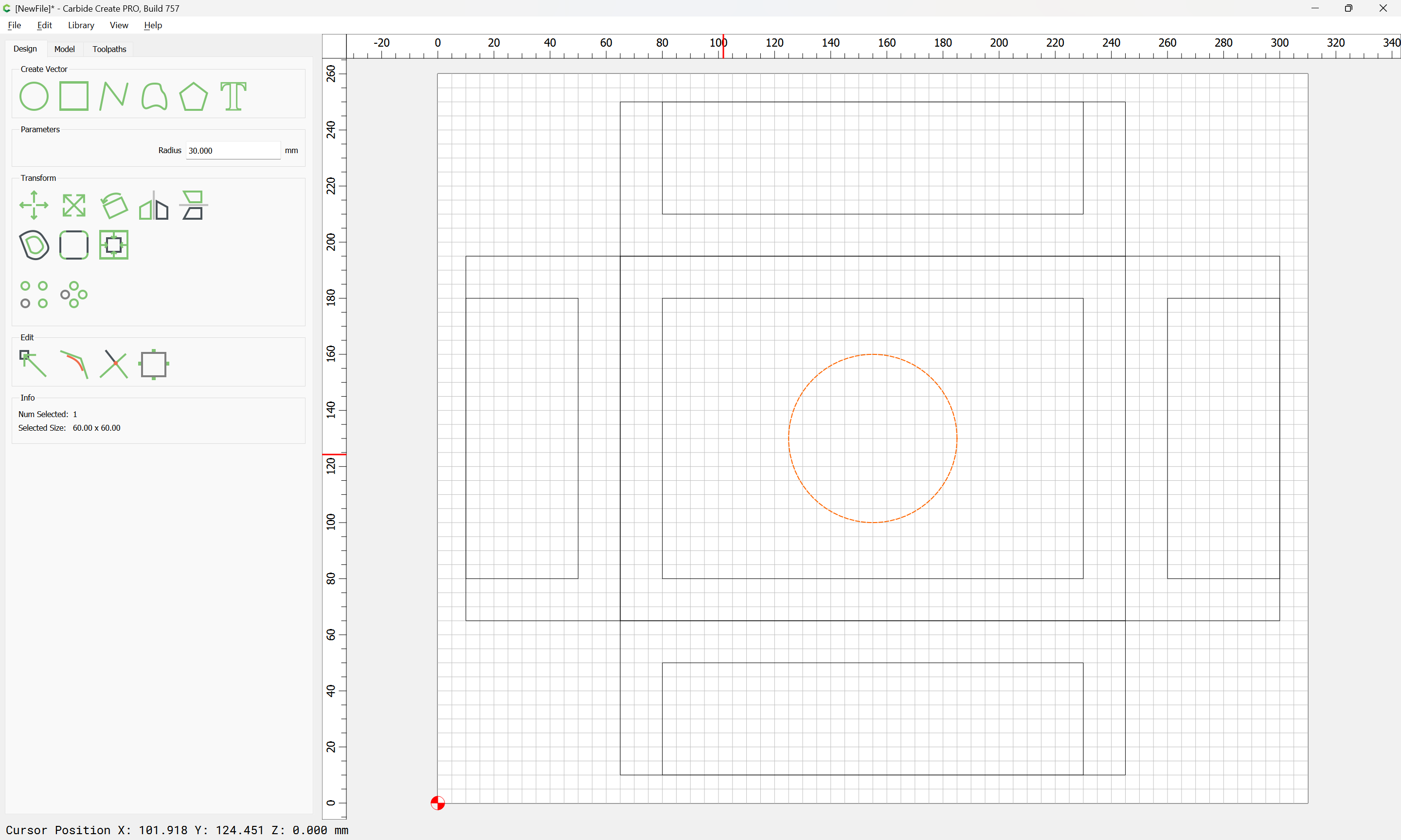
and scale it:
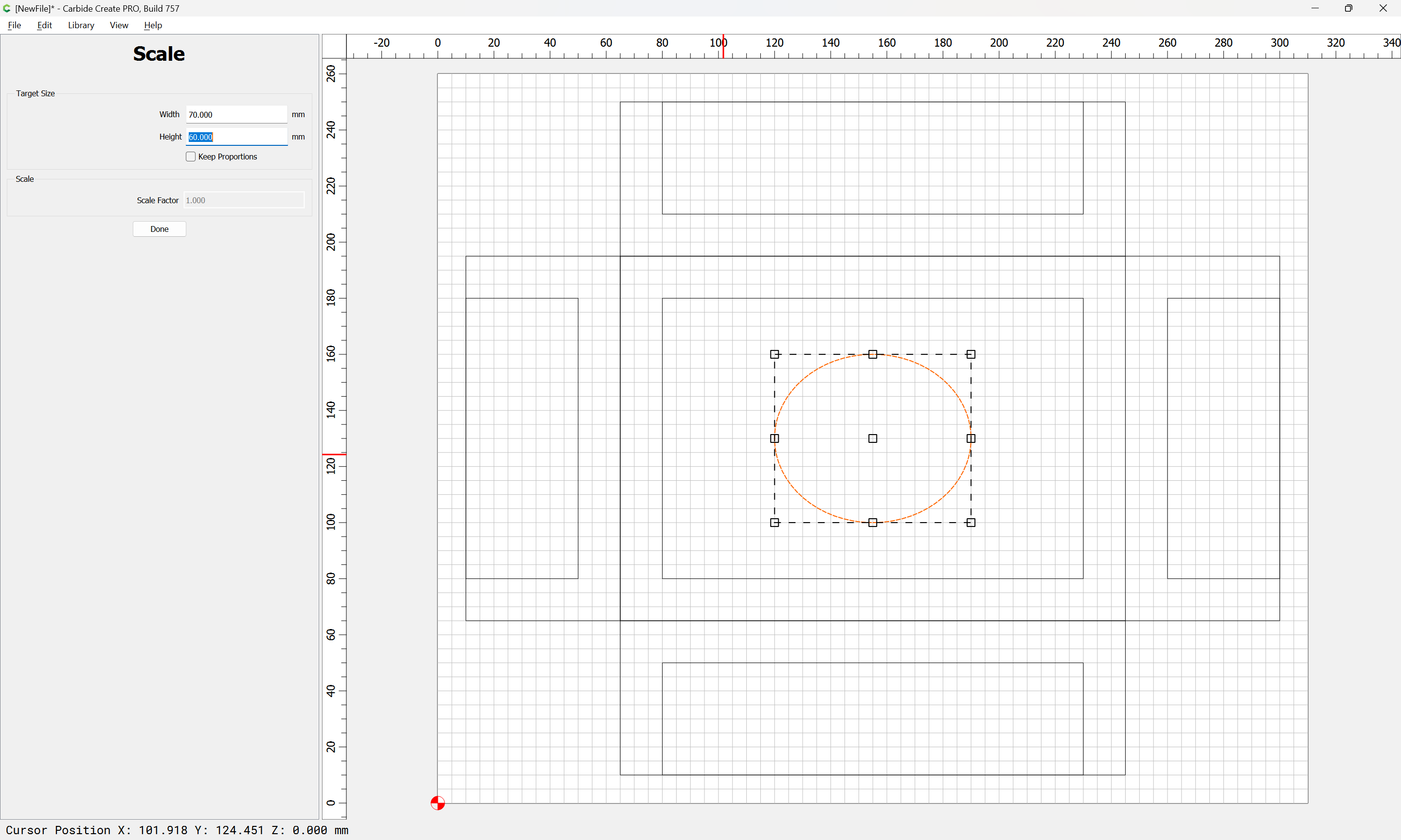
to make it an oval
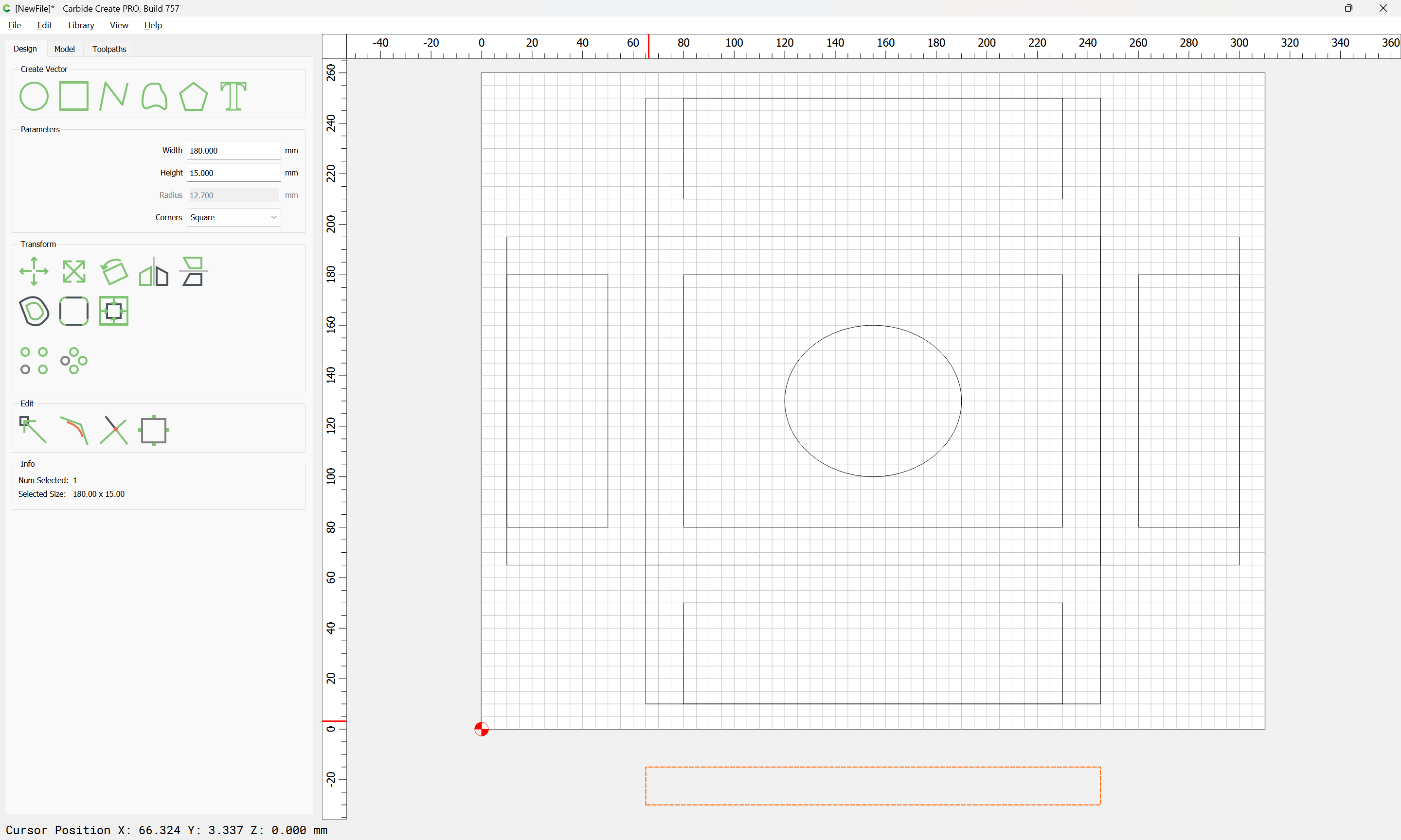
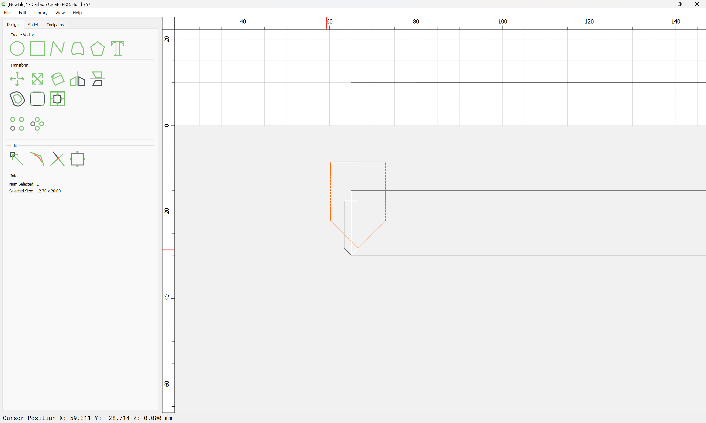
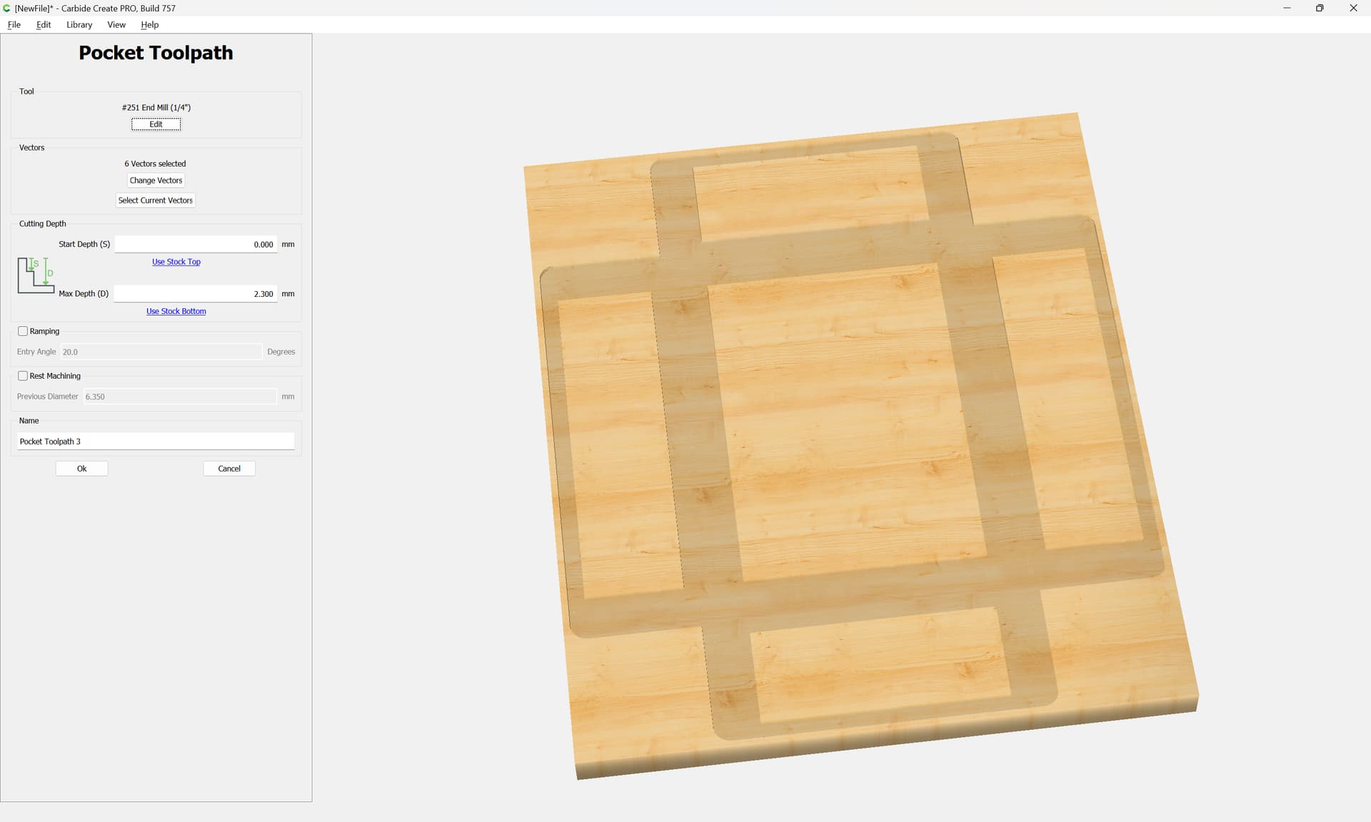
Draw the cut in profile:
and draw up the tooling which will be needed:
- narrow (1/8" diameter) 90 degree V endmill (these are available from Drillman1 on eBay)
- larger 90 degree V endmill (hopefully a #301 will serve)
Or, maybe a different approach will work since this stock is so thick — changing gears:
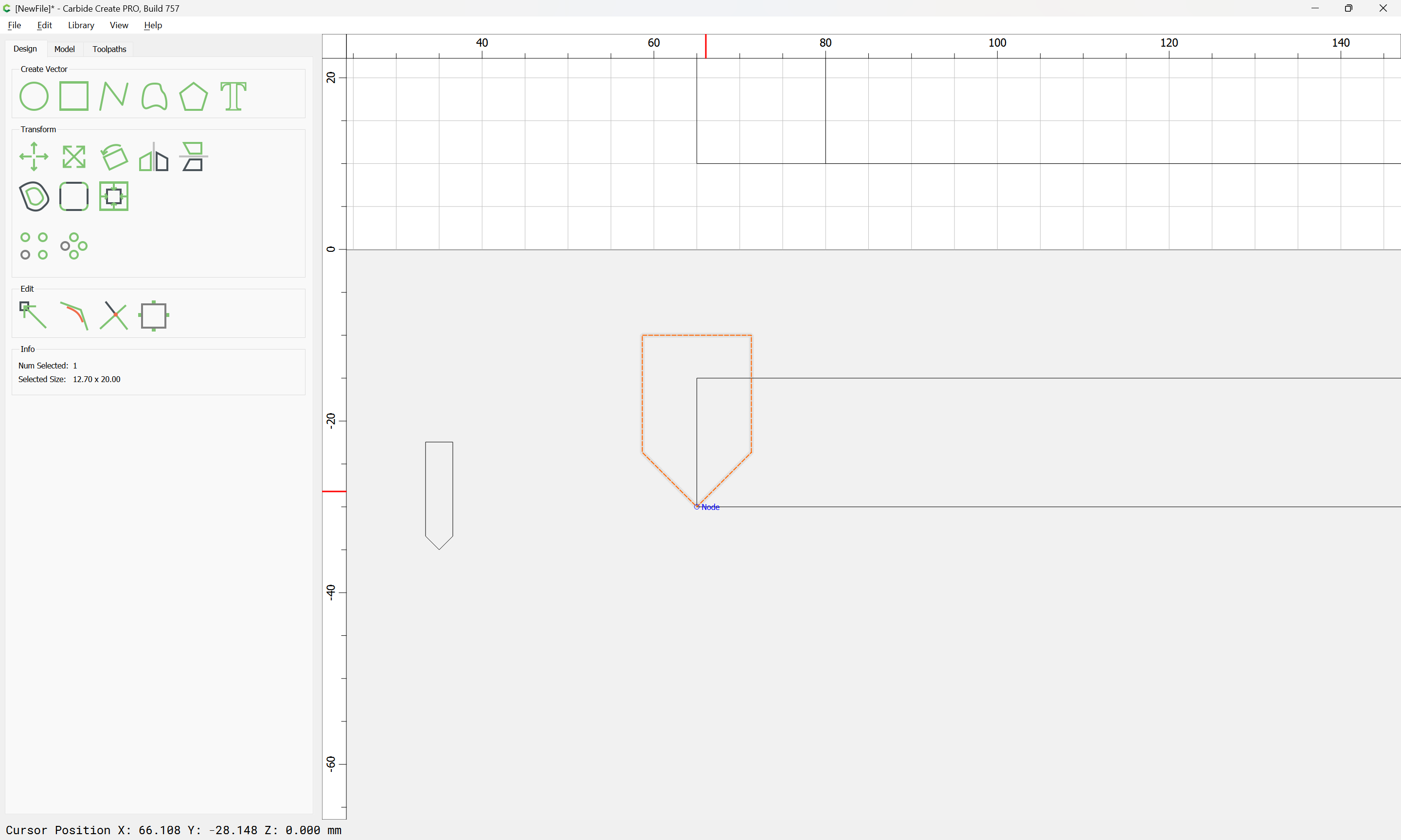
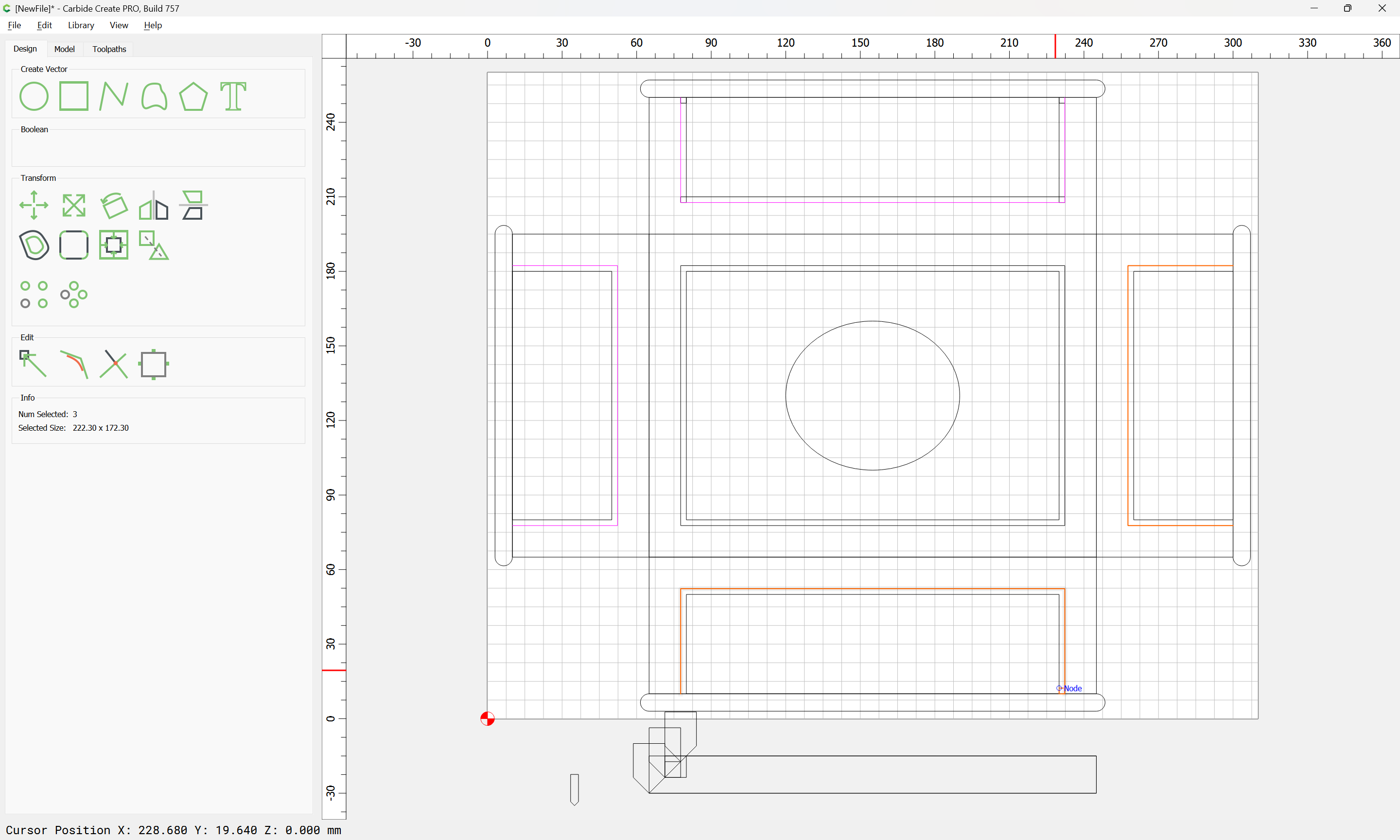
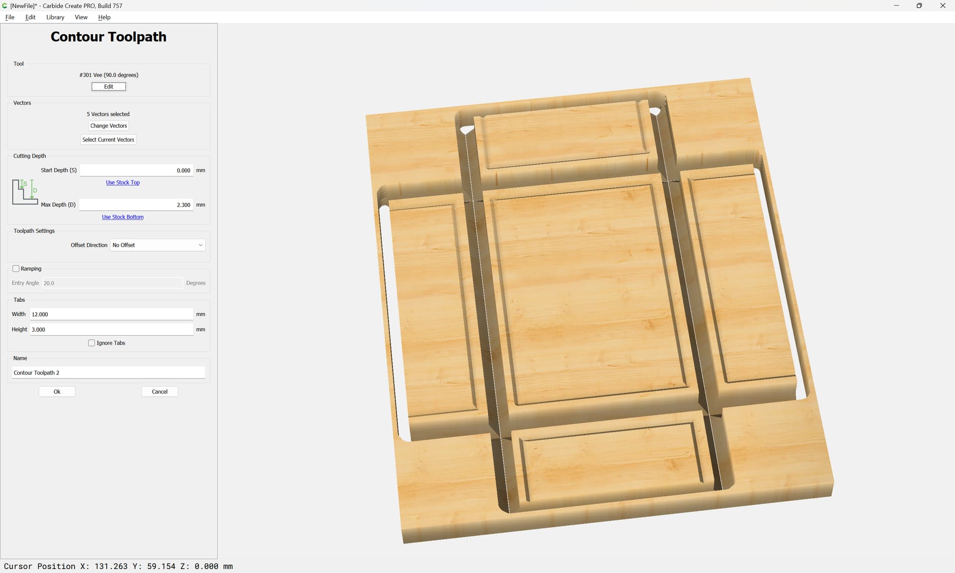
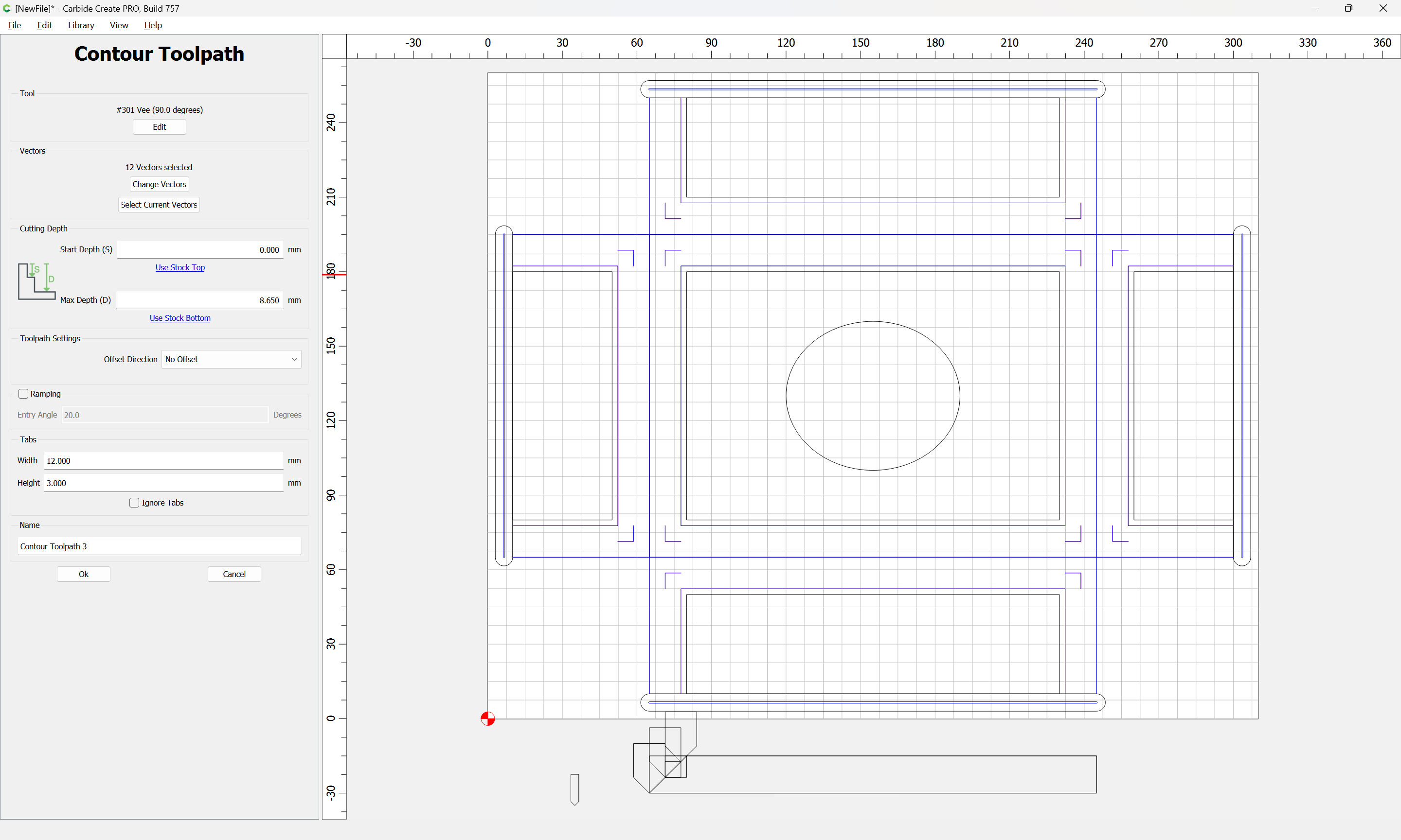
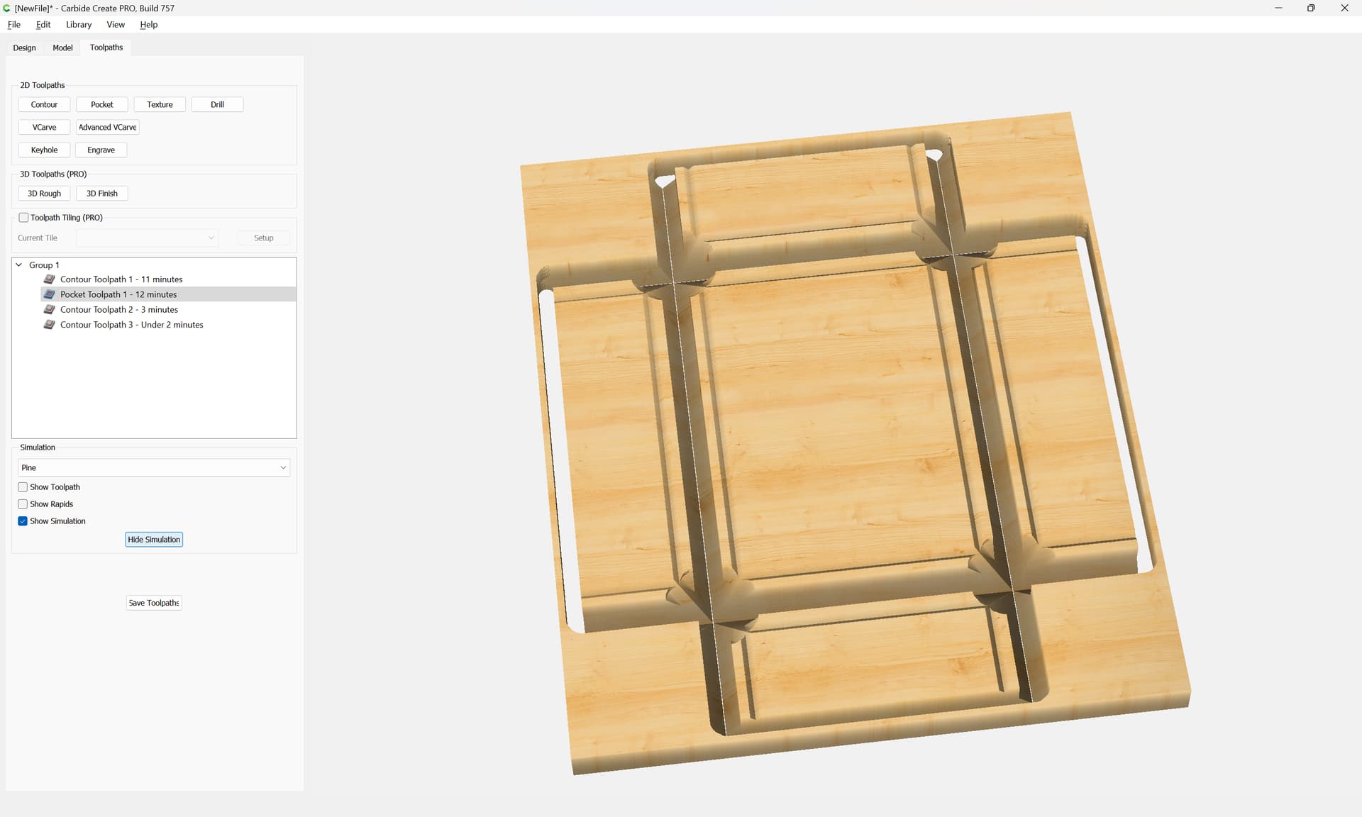
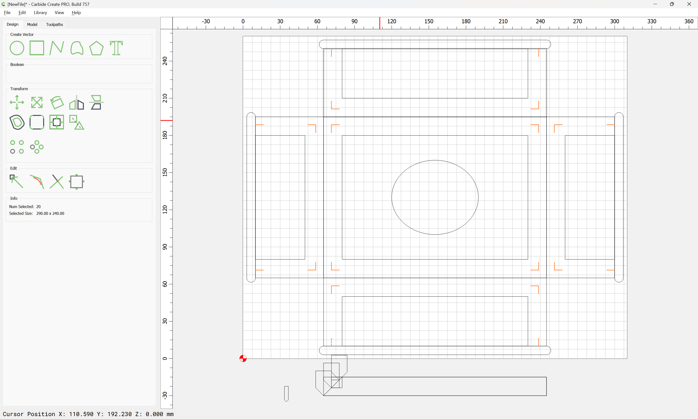
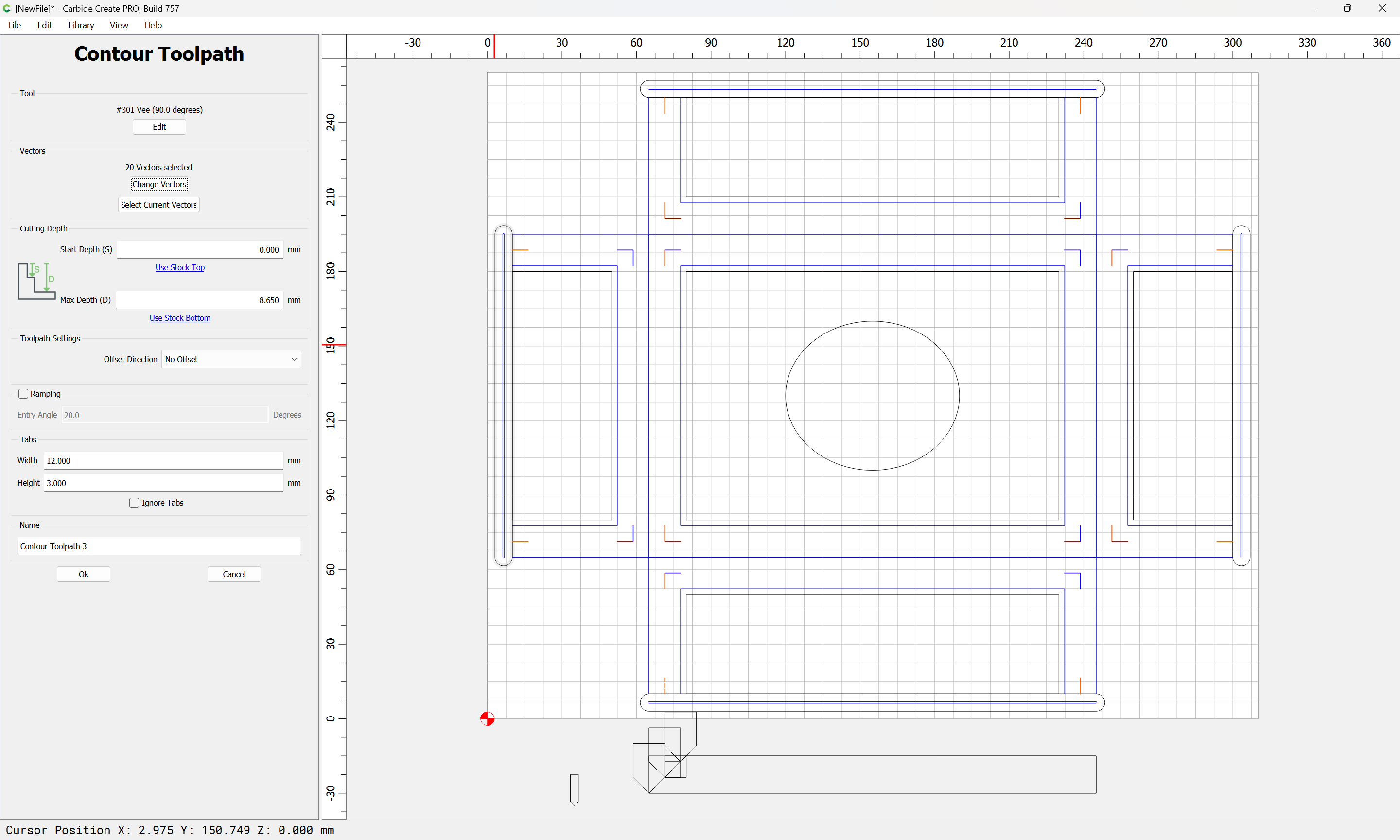
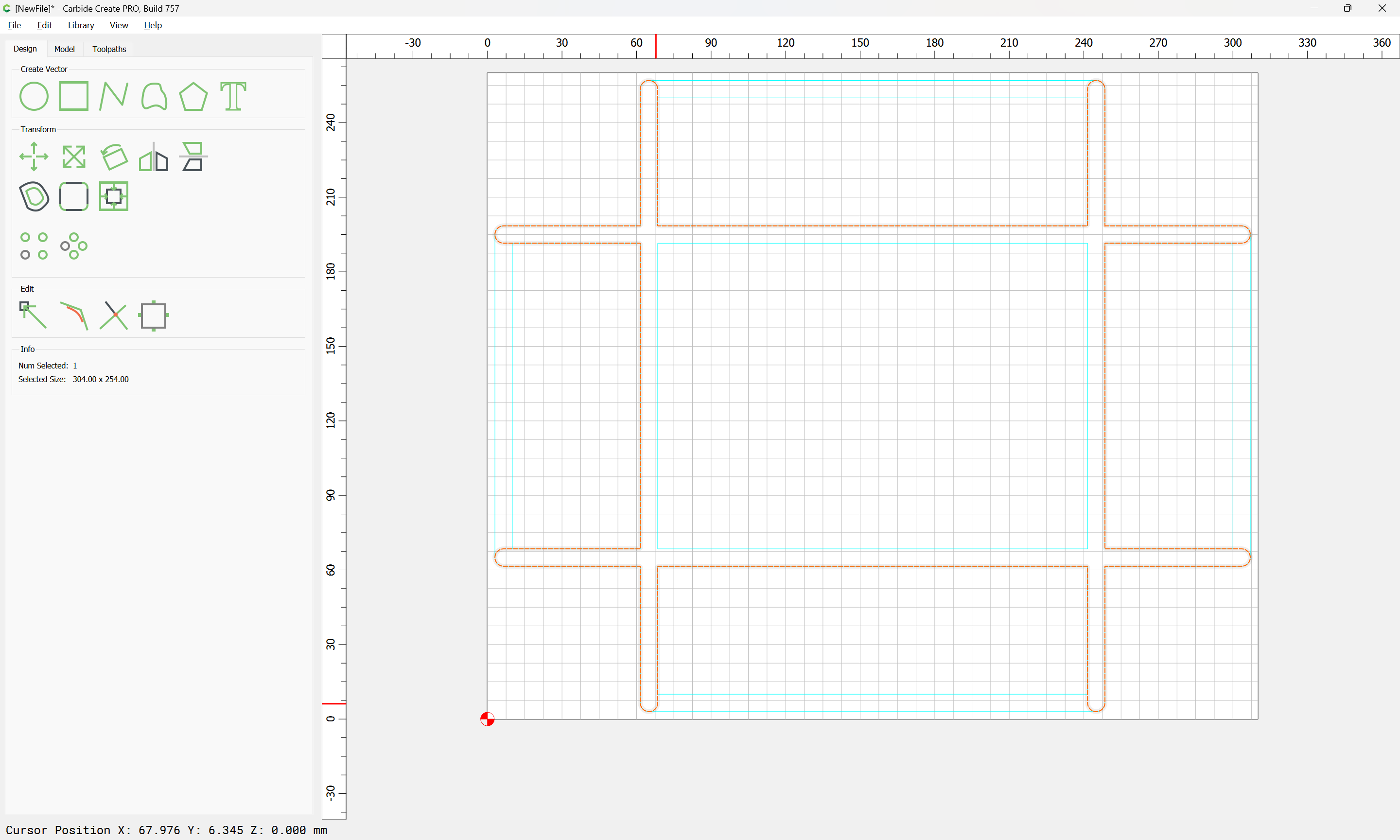
Start with a no offset Contour with a V tool along the parting lines of the parts:
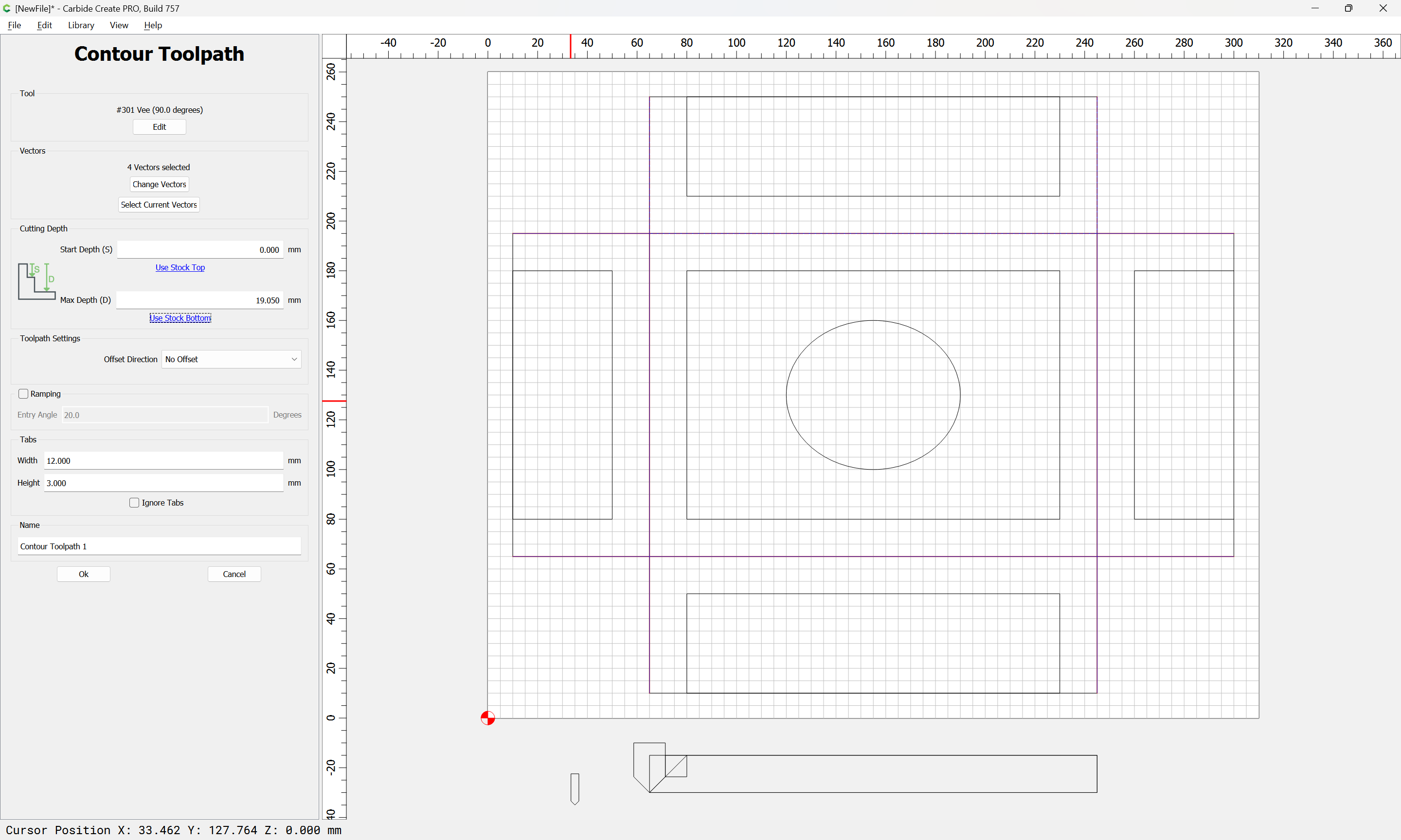
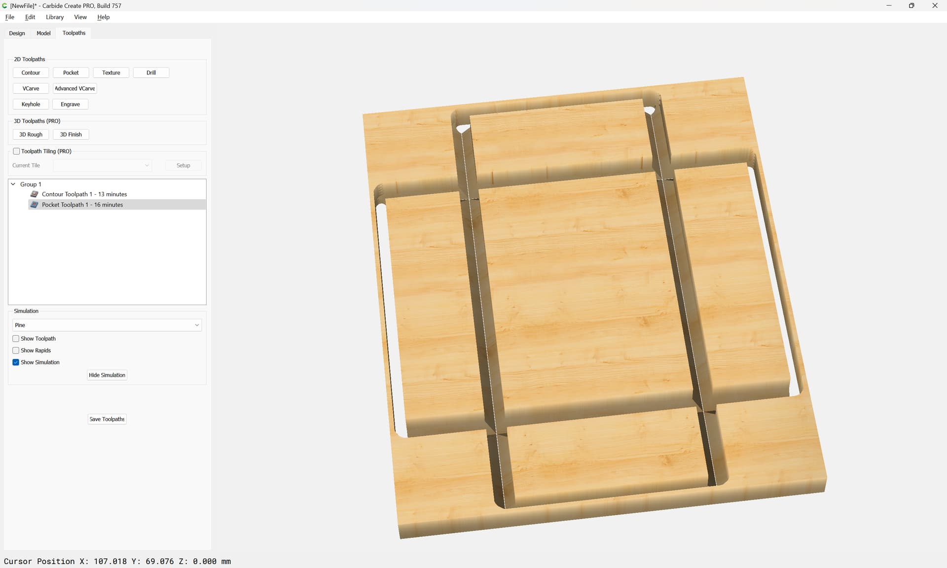
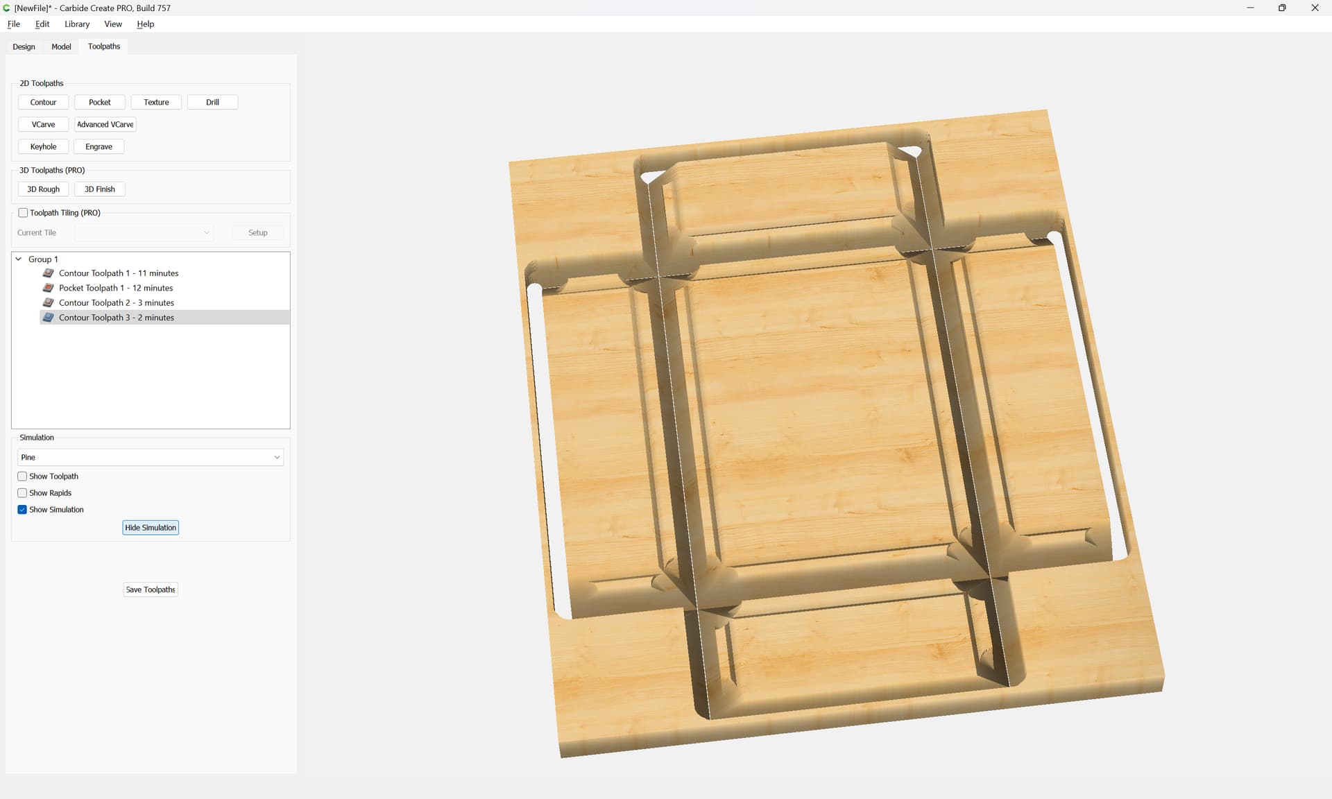
which previews as:
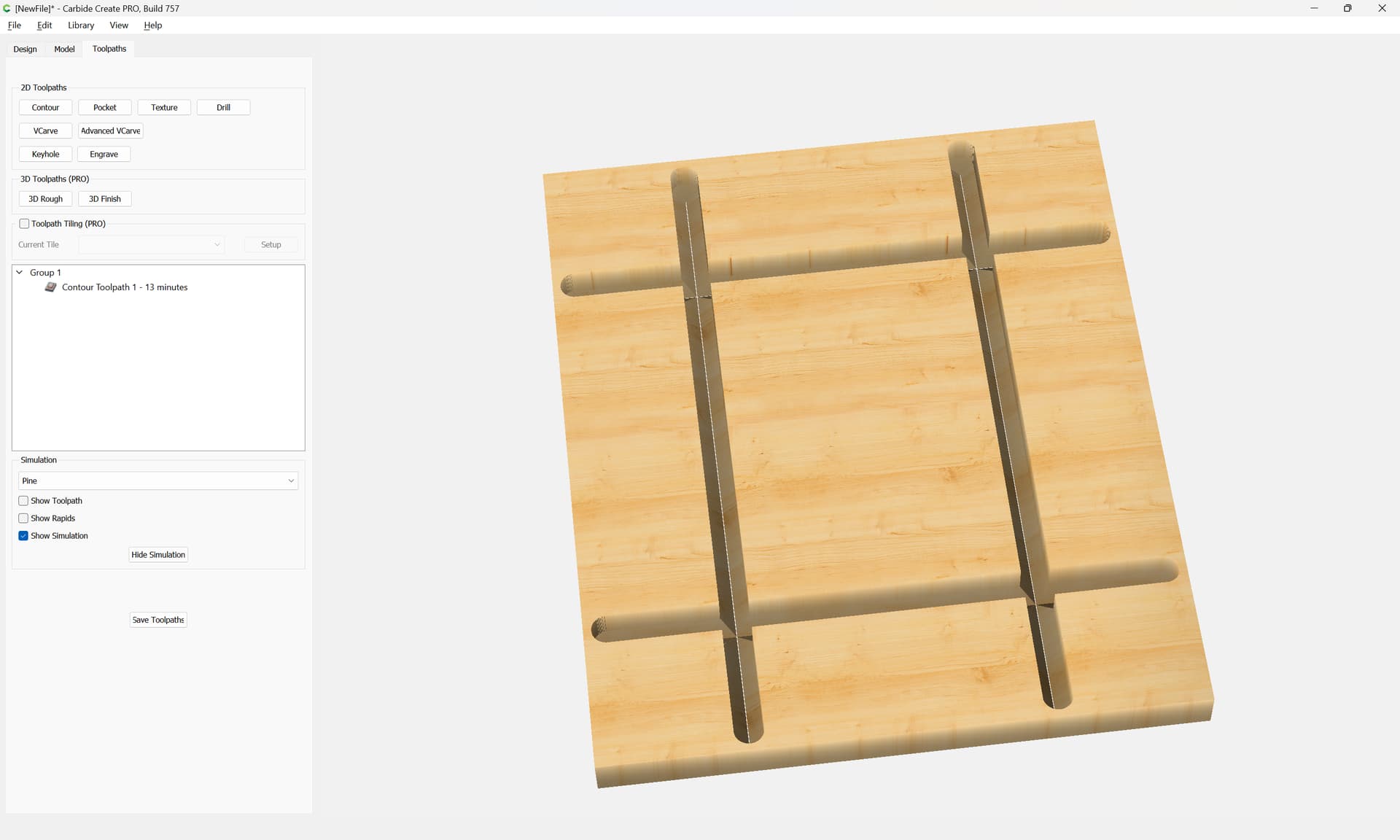
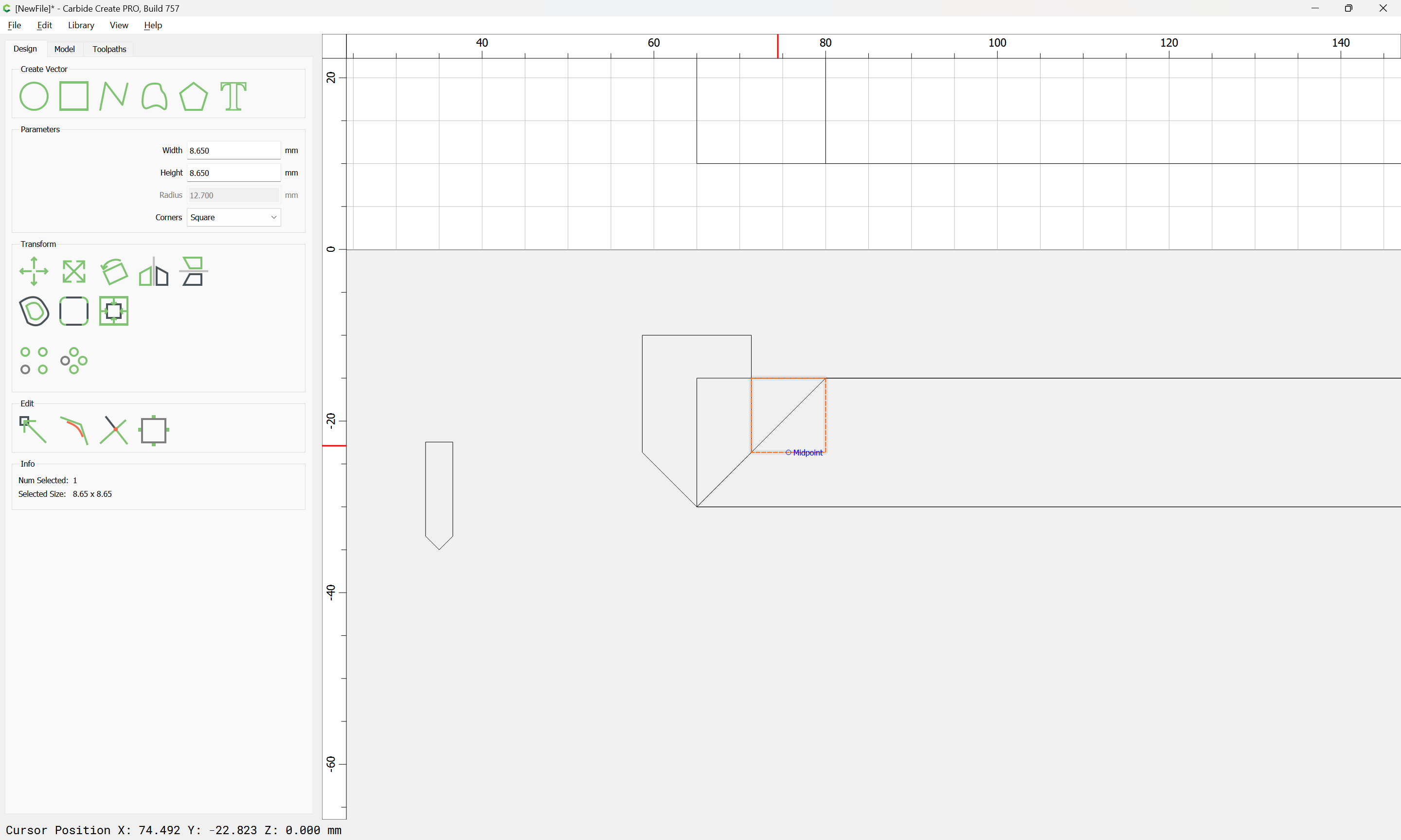
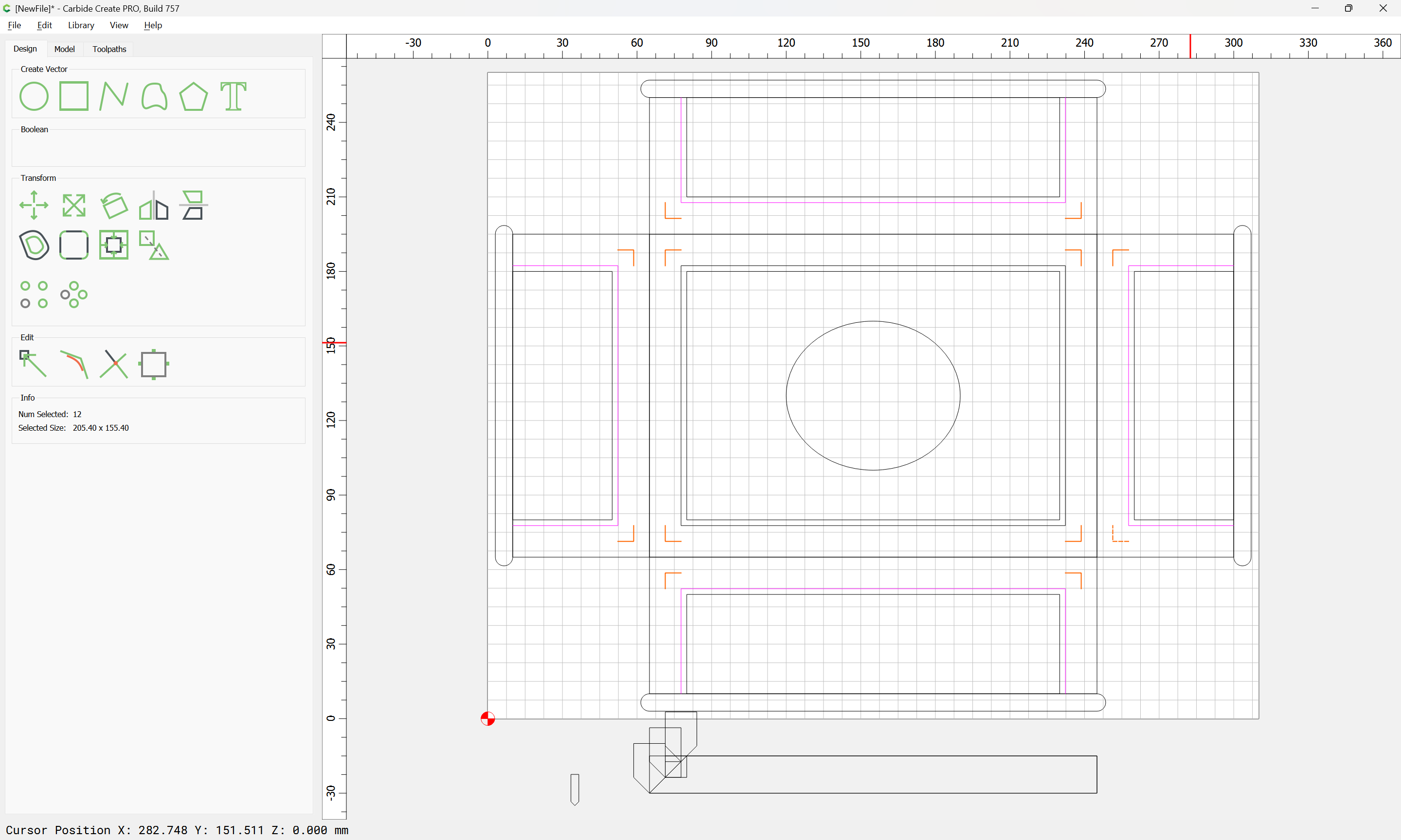
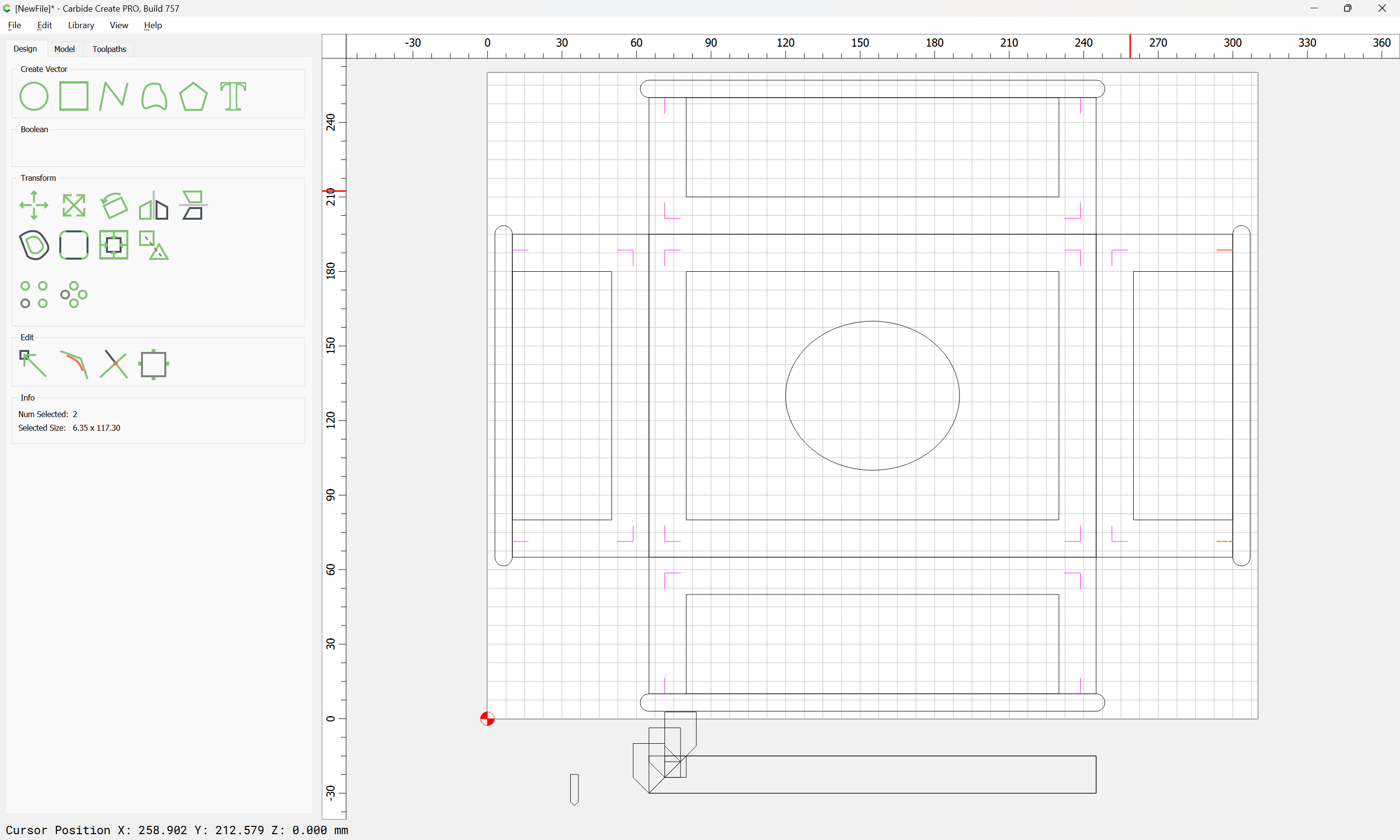
So as to better visualize the parts, we add cuts around the edges to define them:
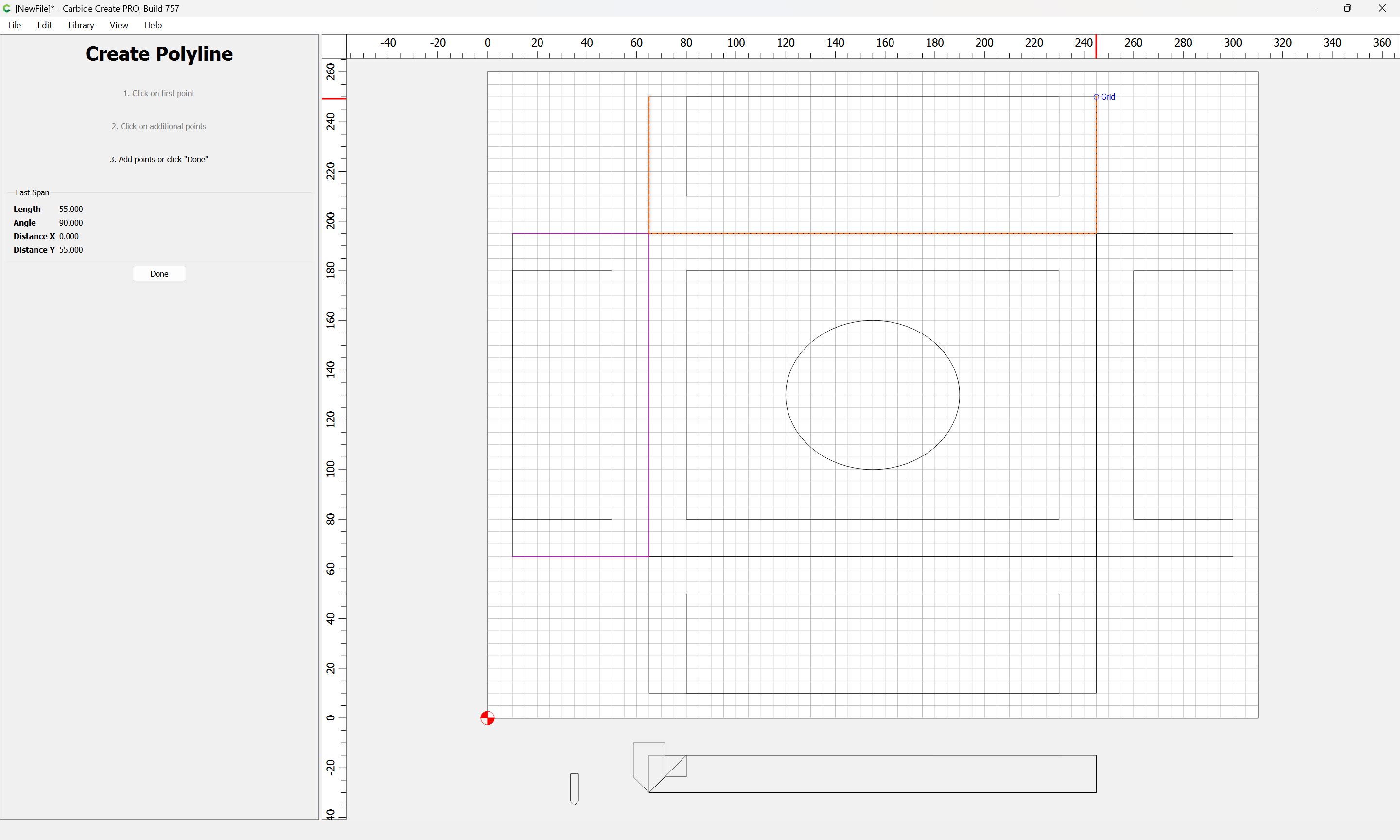
We will need at least 3 passes with a #301 to cut the miters at the corners:
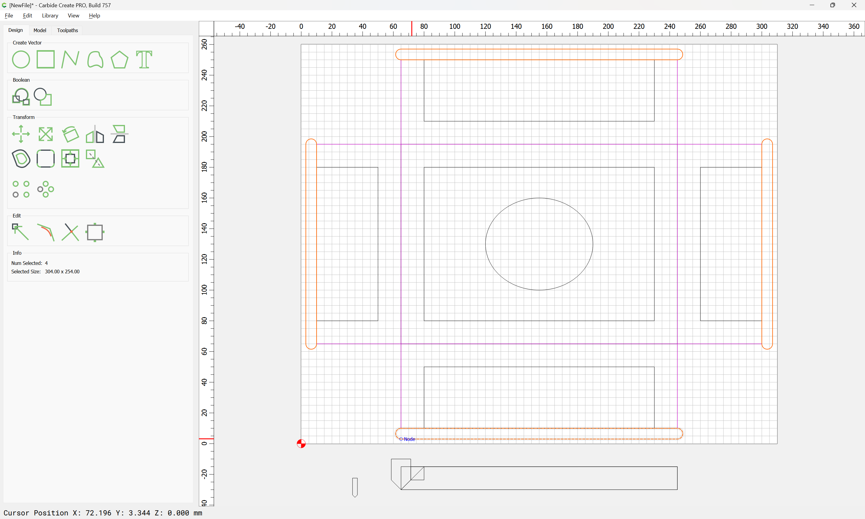
The joinery geometry will be easiest if the shallowest pass is made all the way around all the parts, so we draw this in:
Then it is simply necessary to clean up the corners:
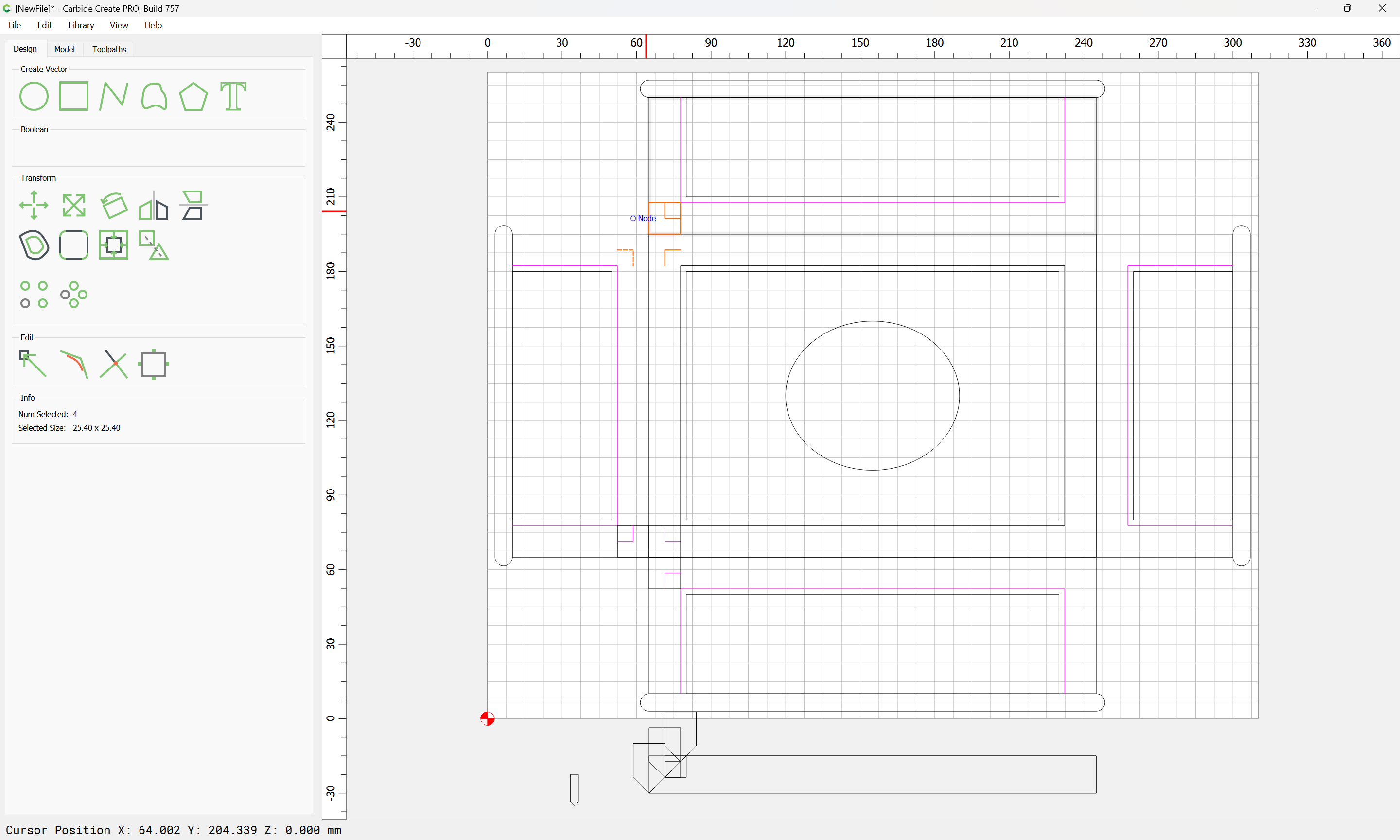
(it may be necessary to extend those a bit, and it was also necessary to correct the stock thickness)
Then it is simply a matter of drawing in the geometry for cutting the pockets for the joinery.
One further modification might be to cut in miters at the open ends of the joinery — would probably look better:
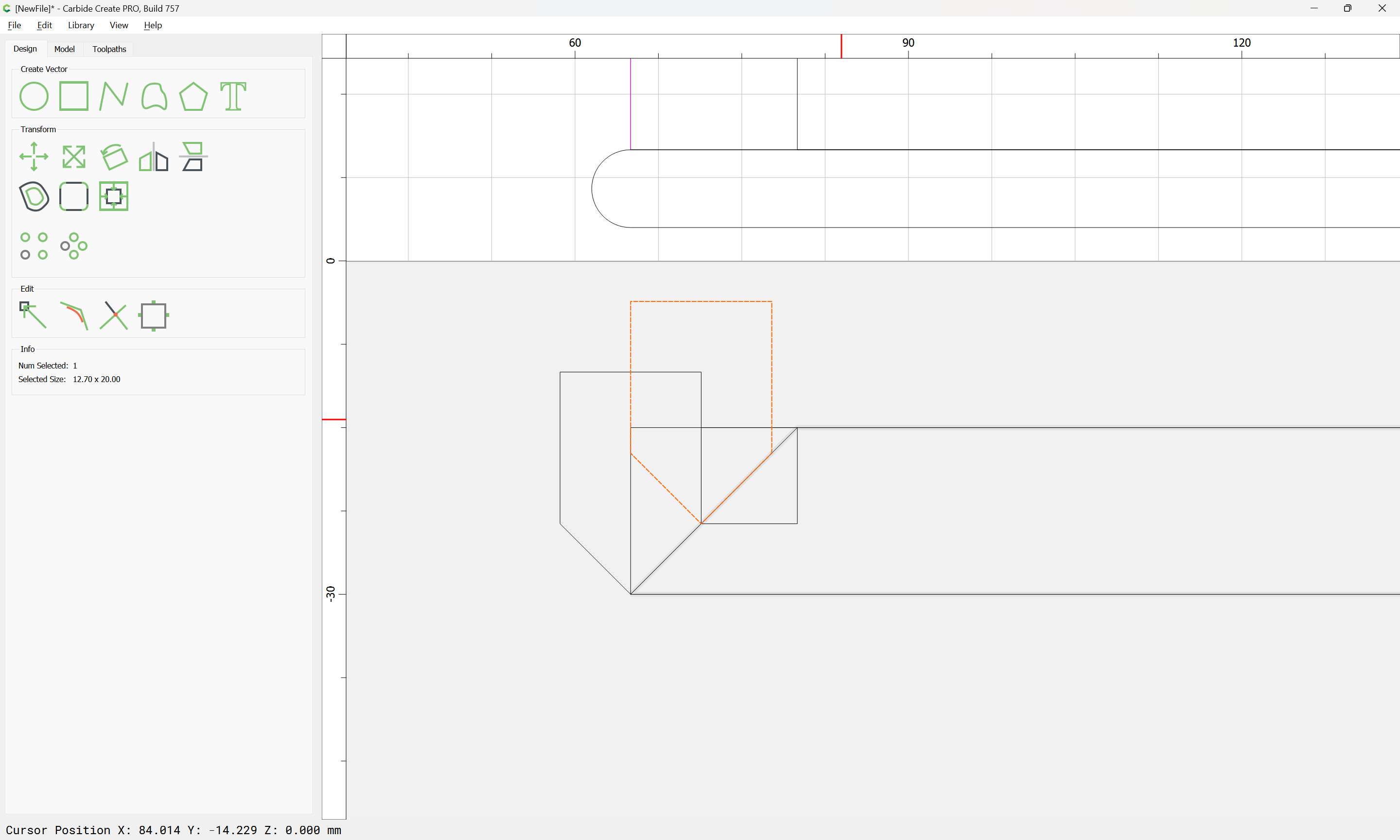
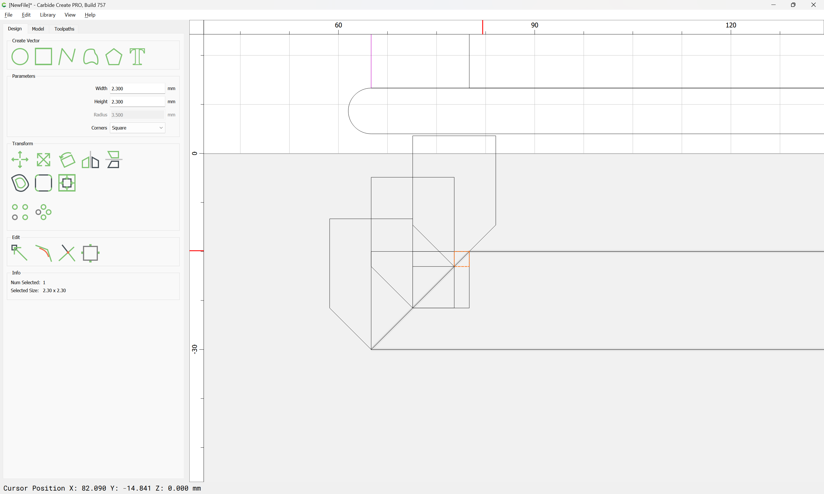
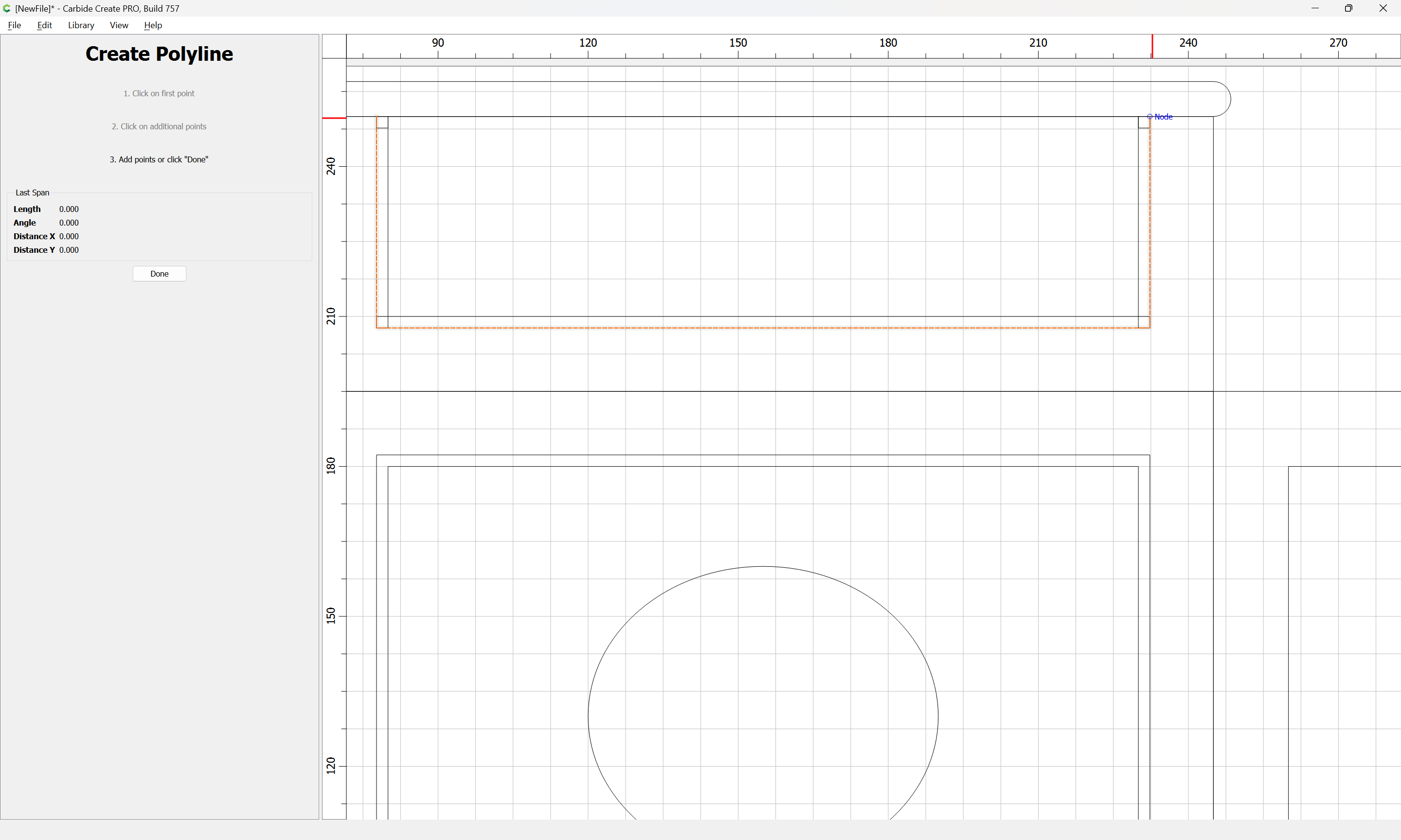
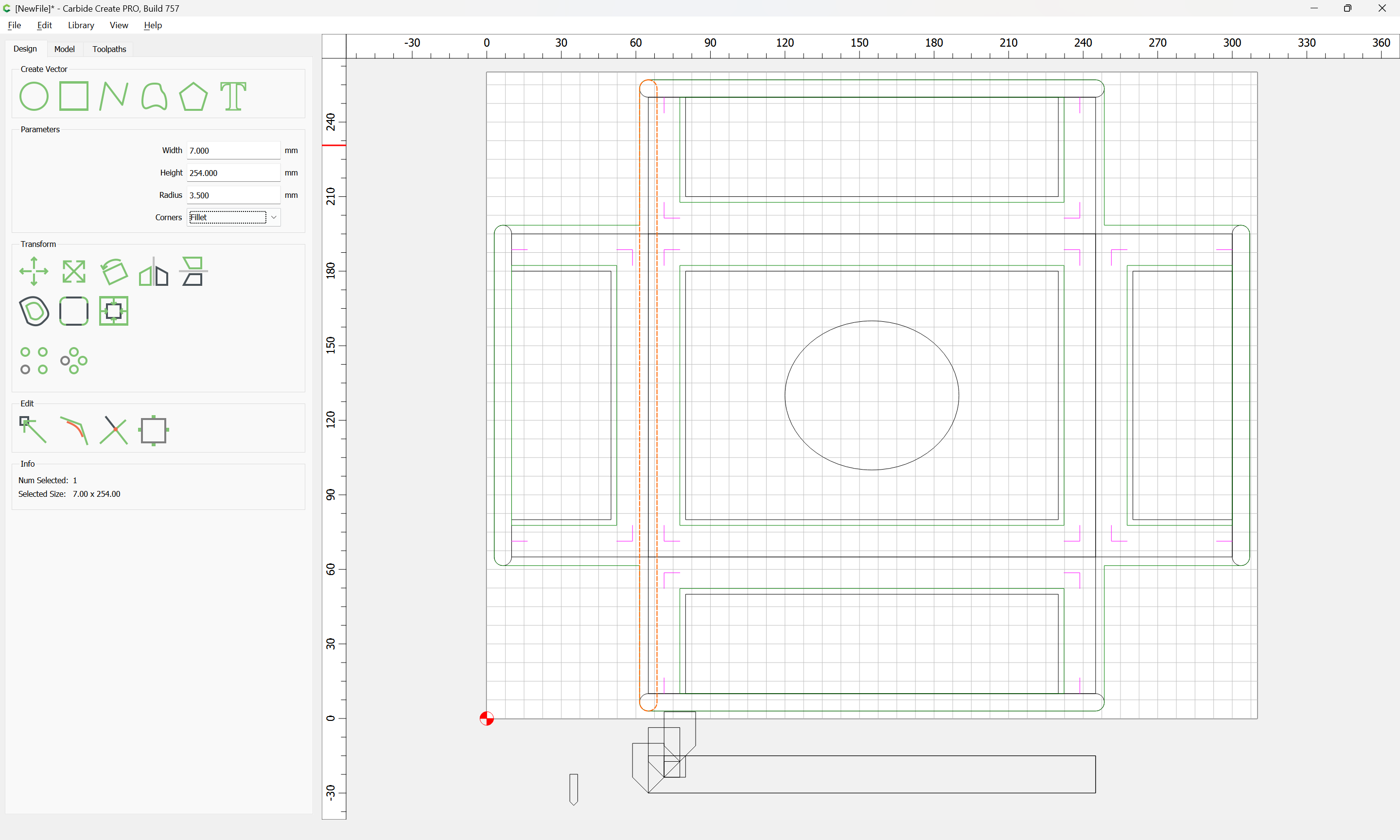
Lastly we draw in the geometry for the box joint joinery:
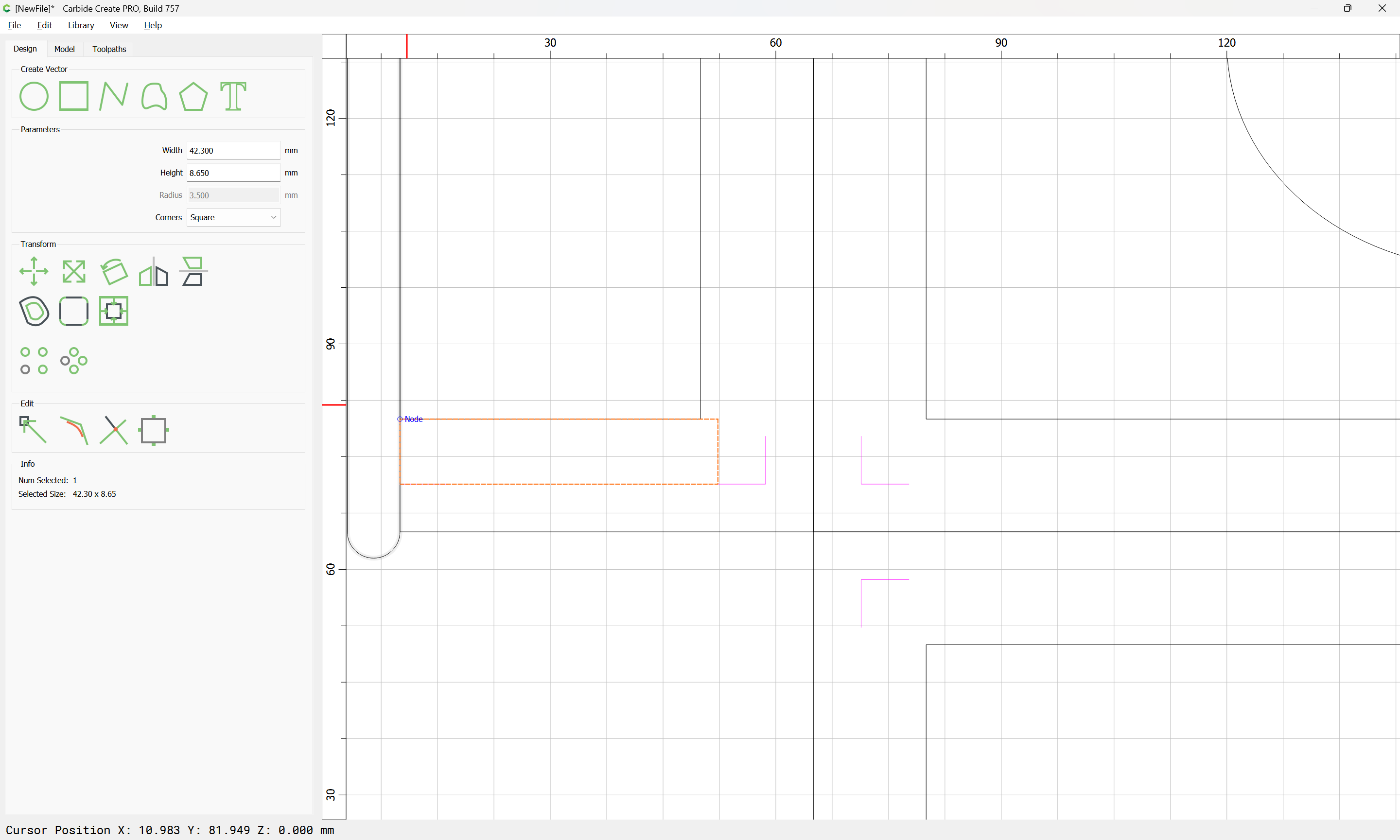
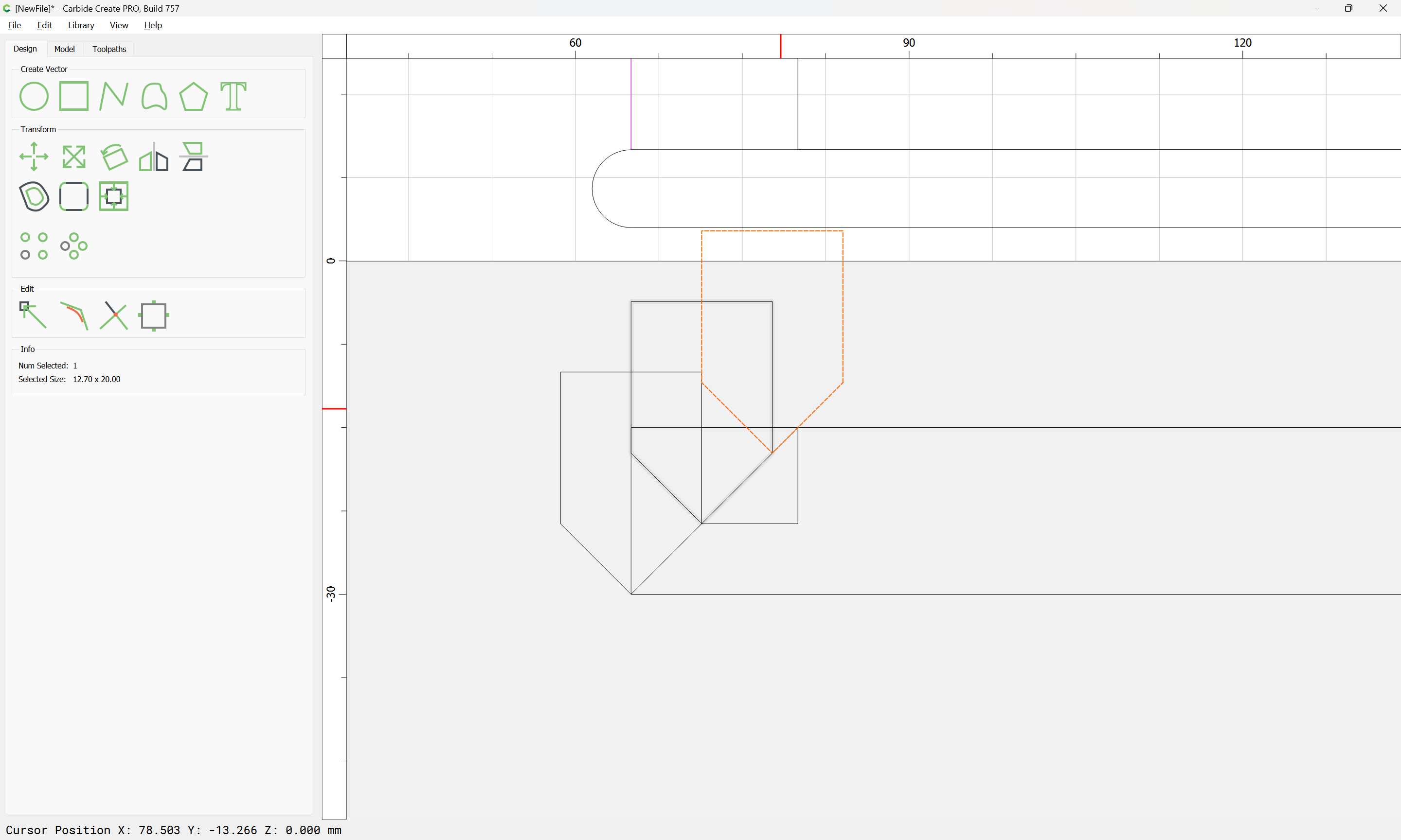
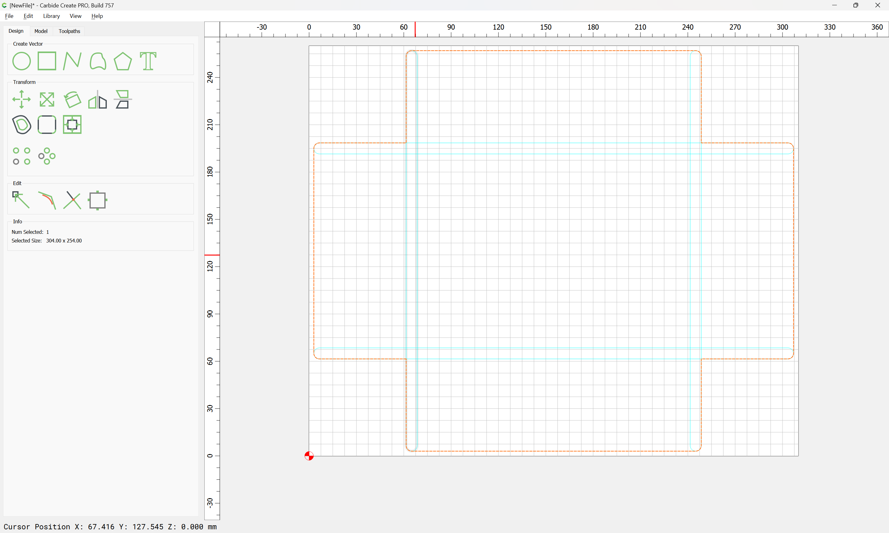
That is over-wide, and needs to be shorter on the left, so we draw from the other edge:
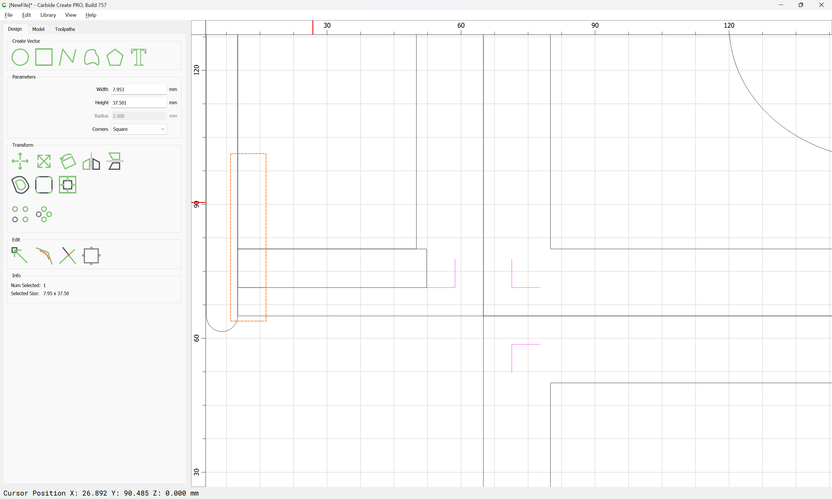
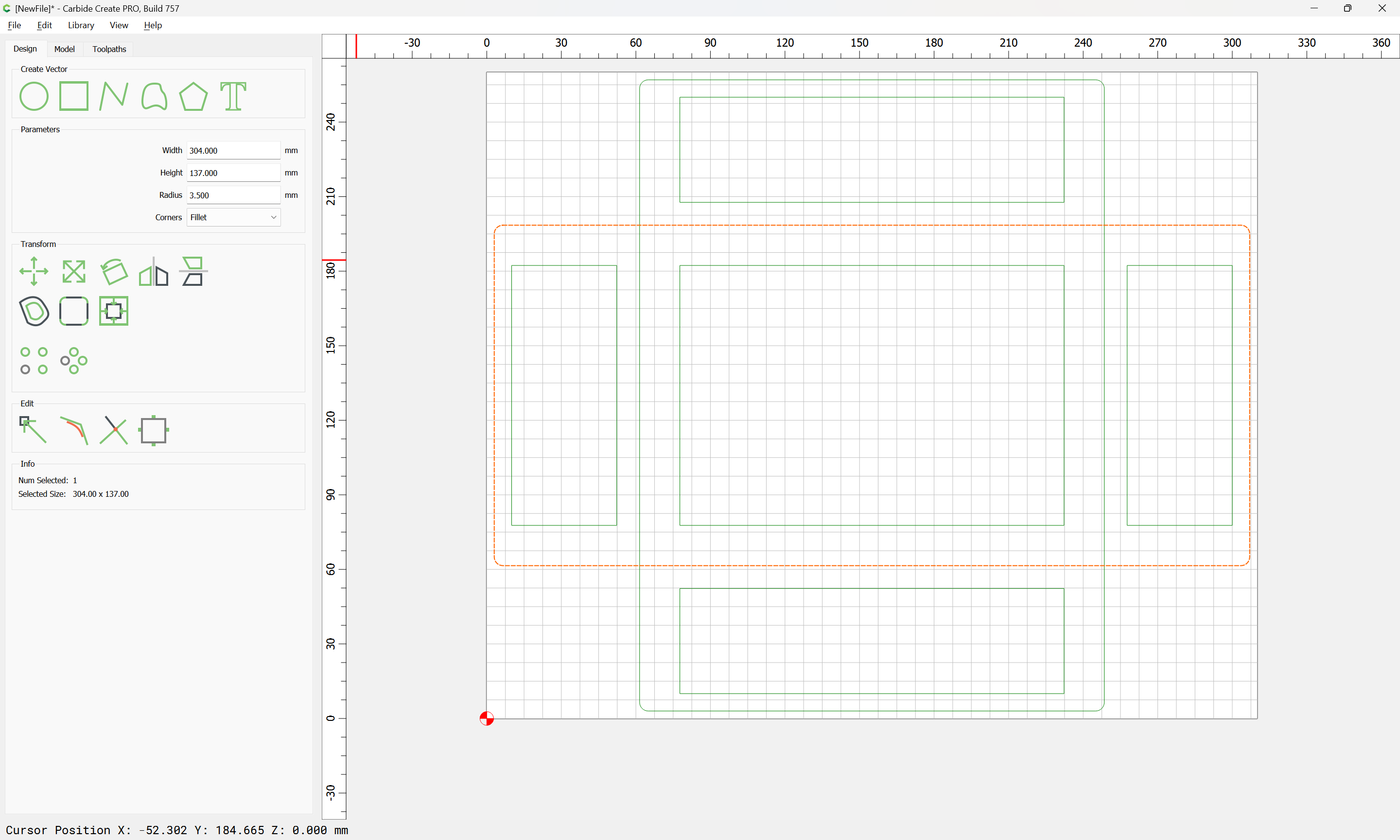
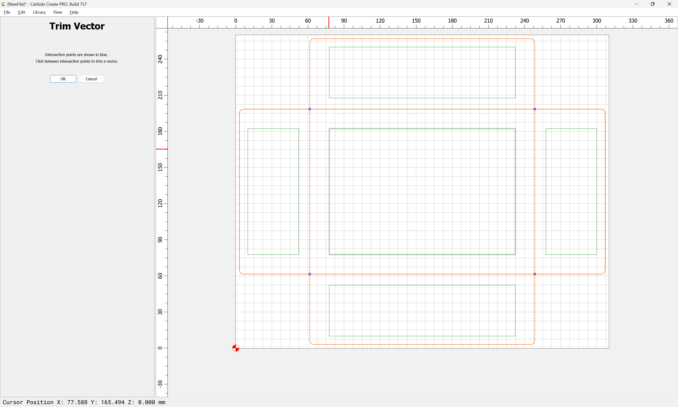
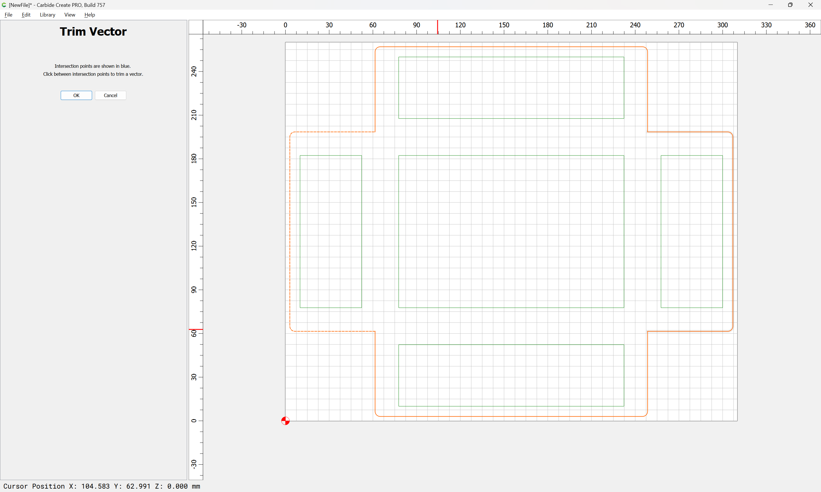
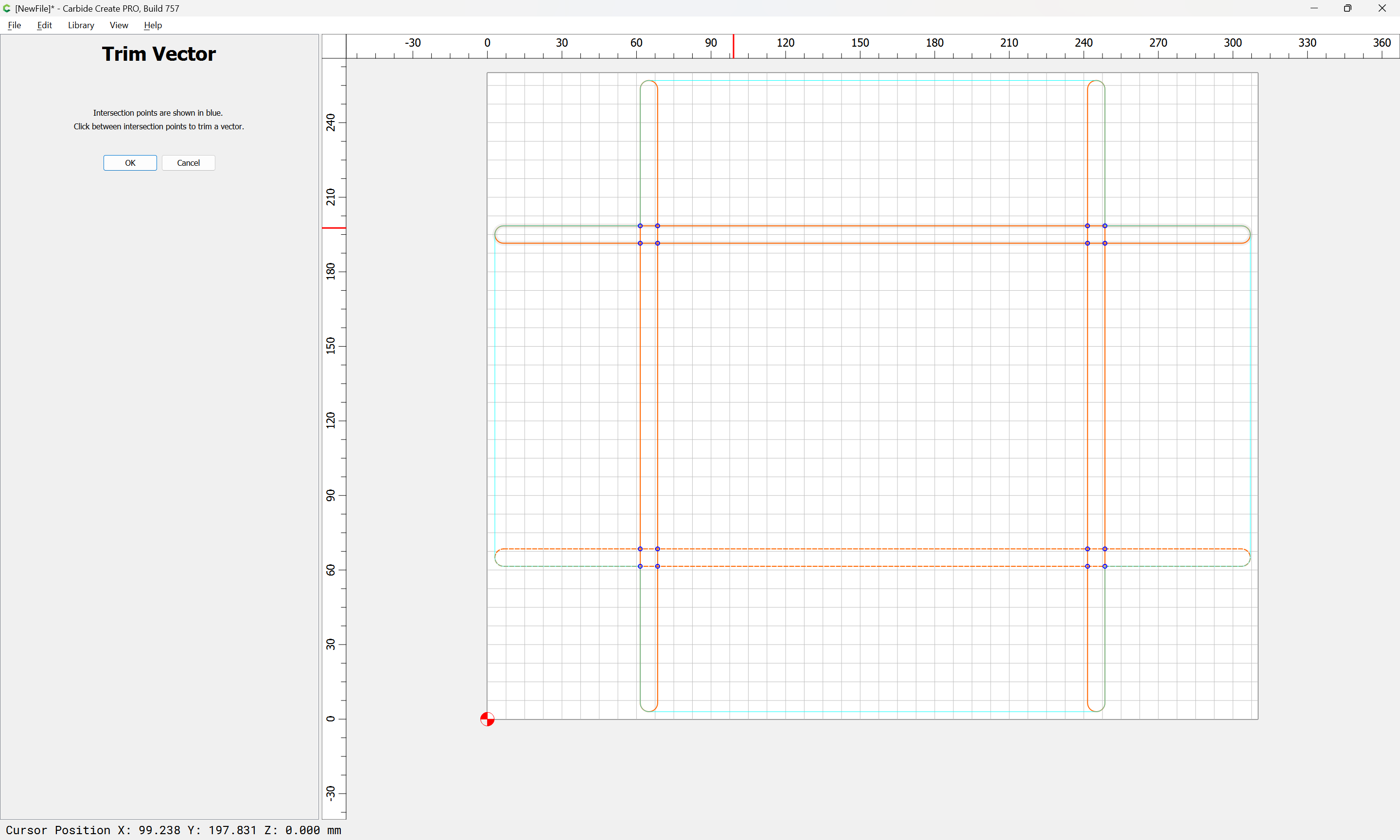
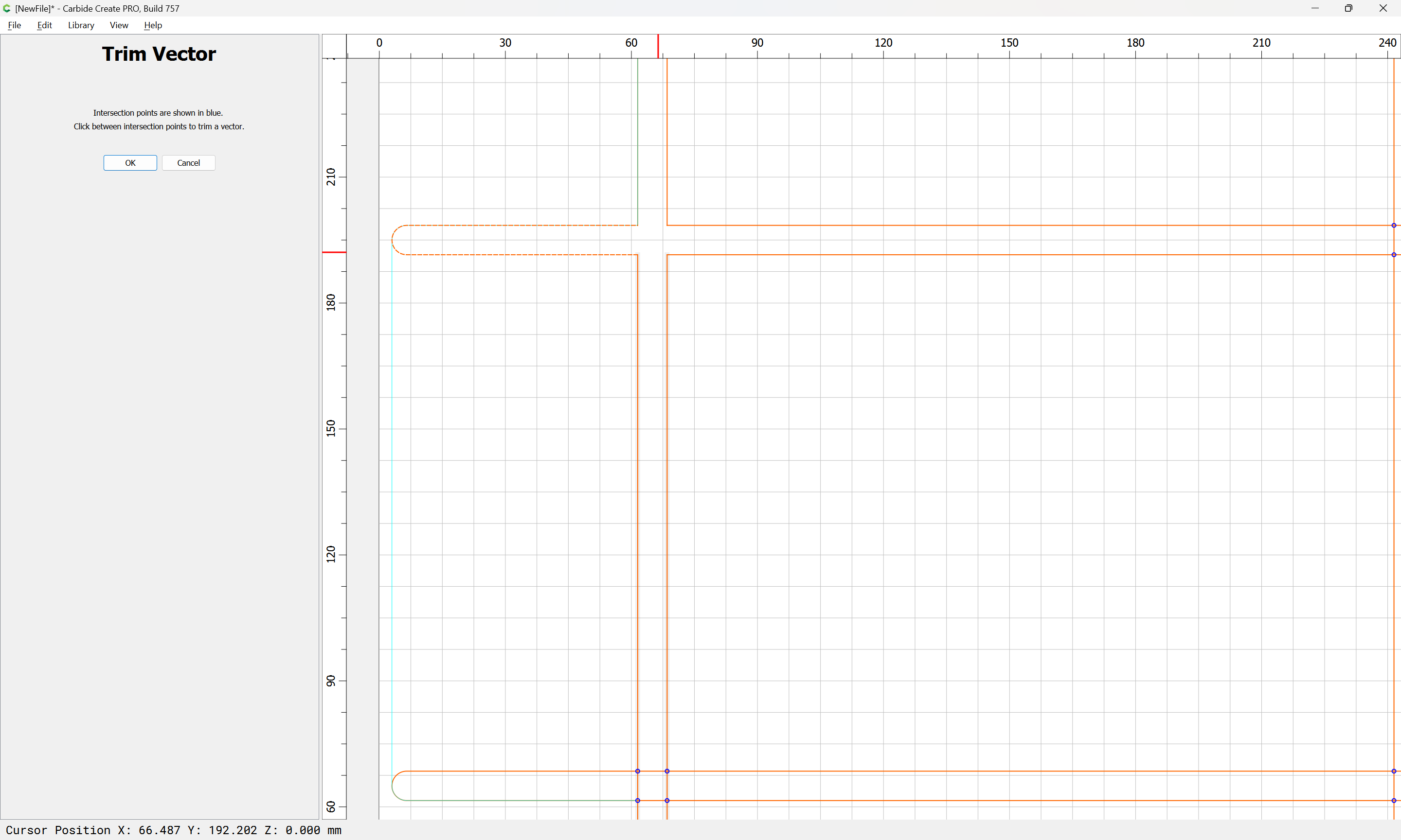
and trim:
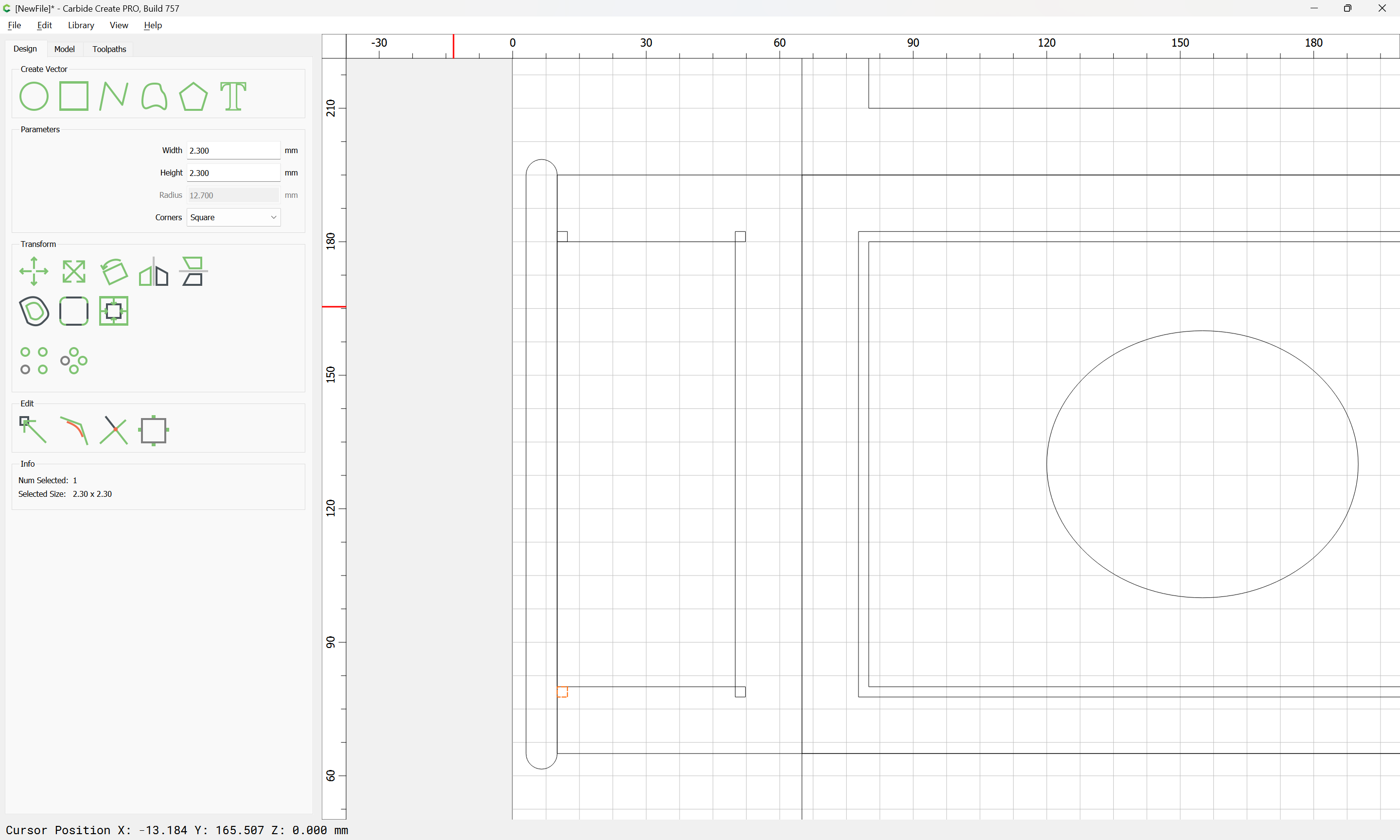
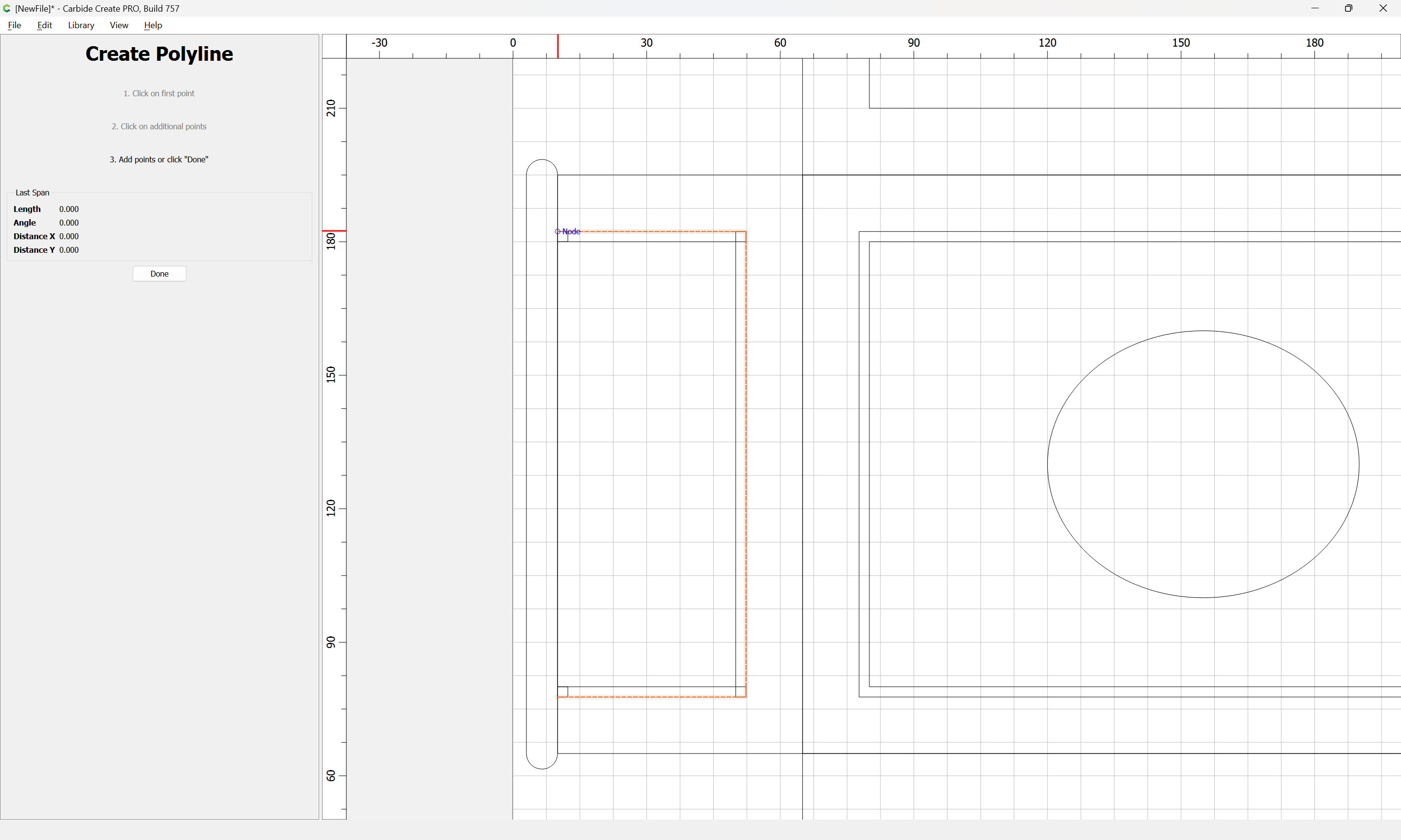
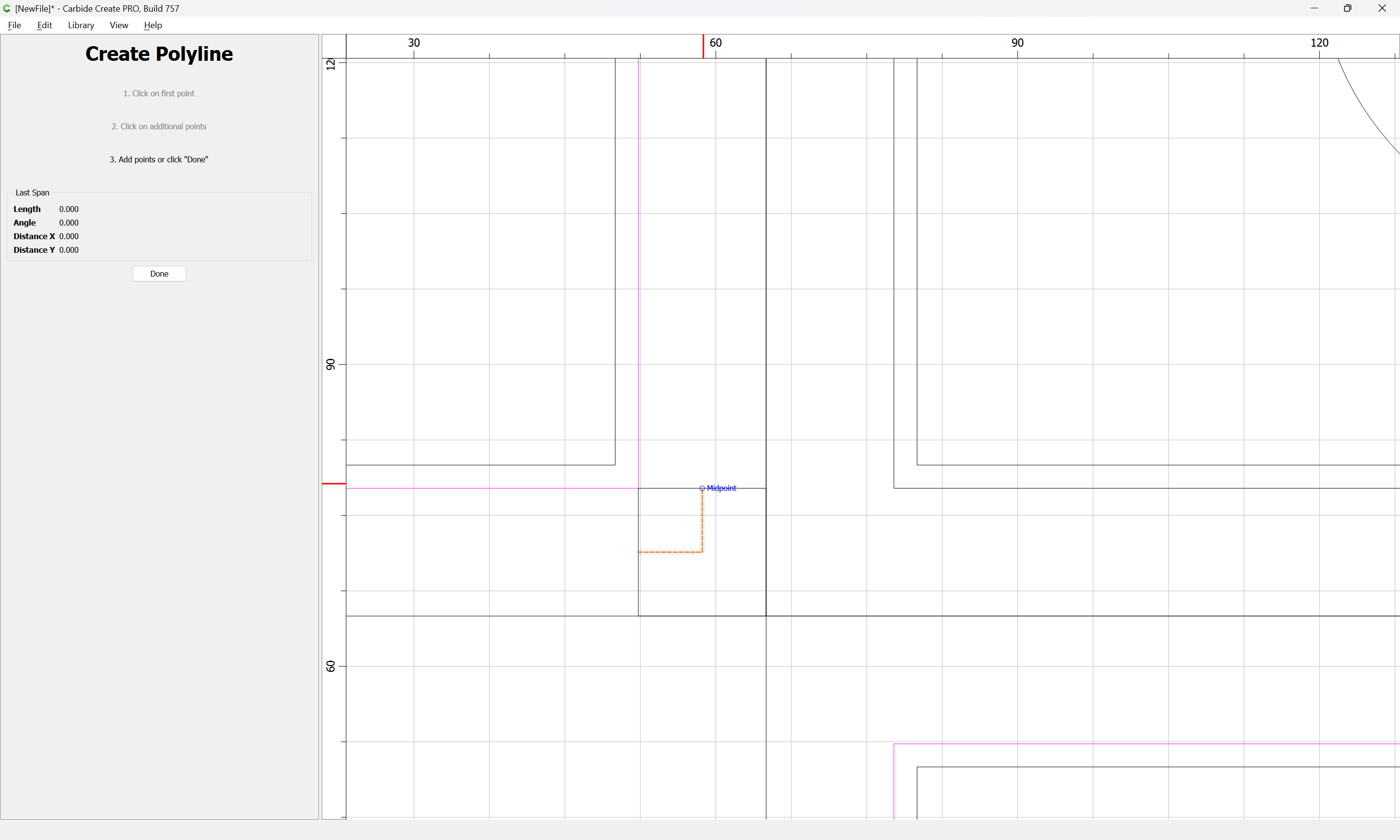
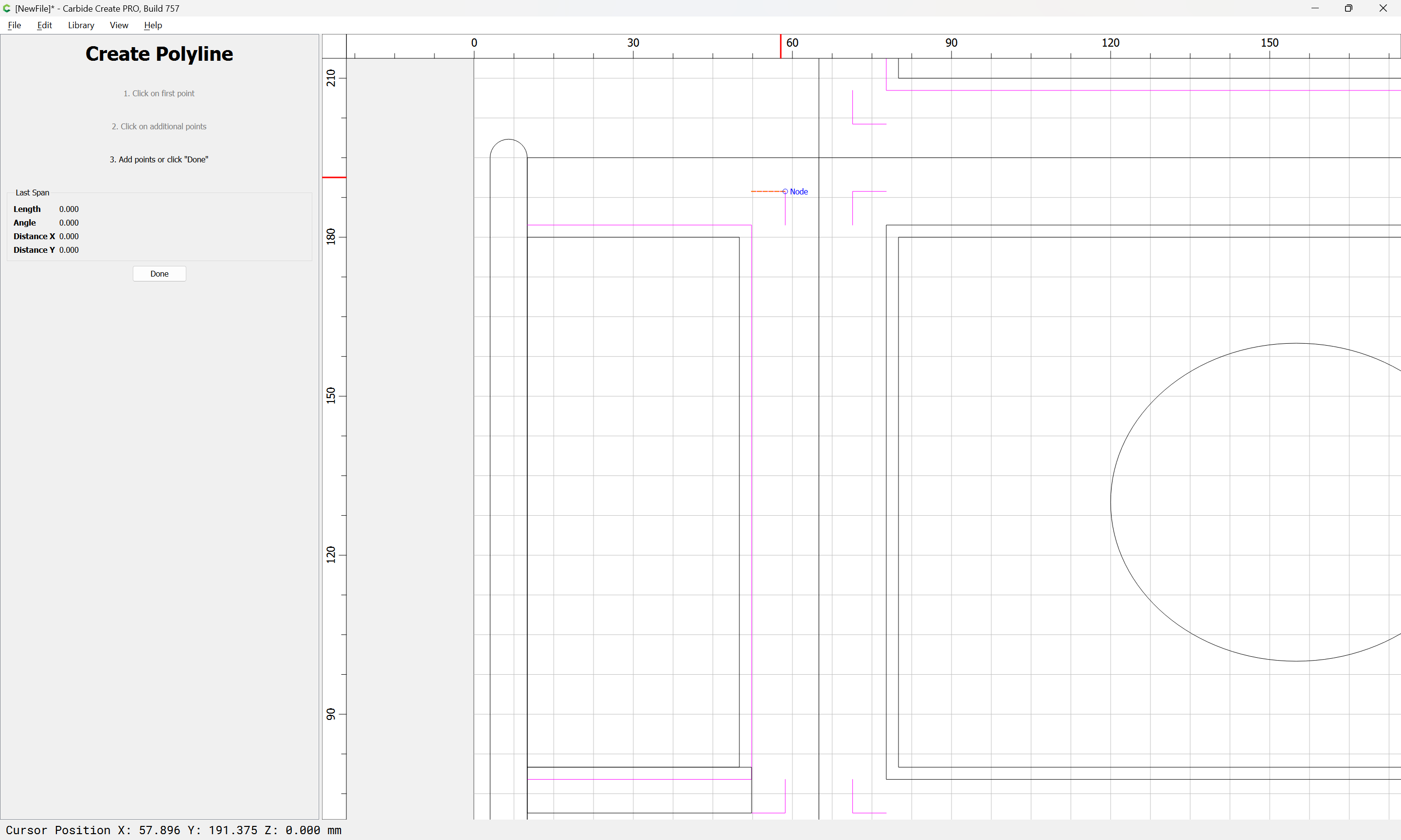
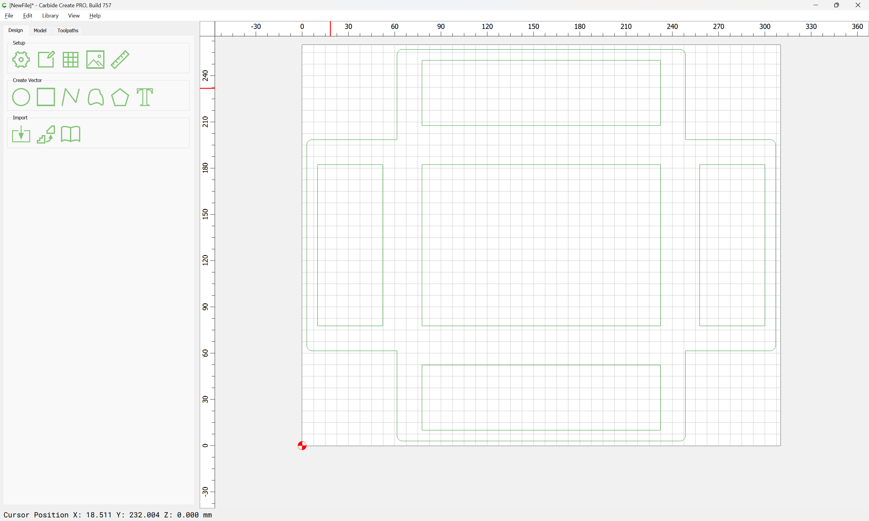
Since it’s nicer working w/ a rectangle than a polyline, we redraw:
and delete the original.
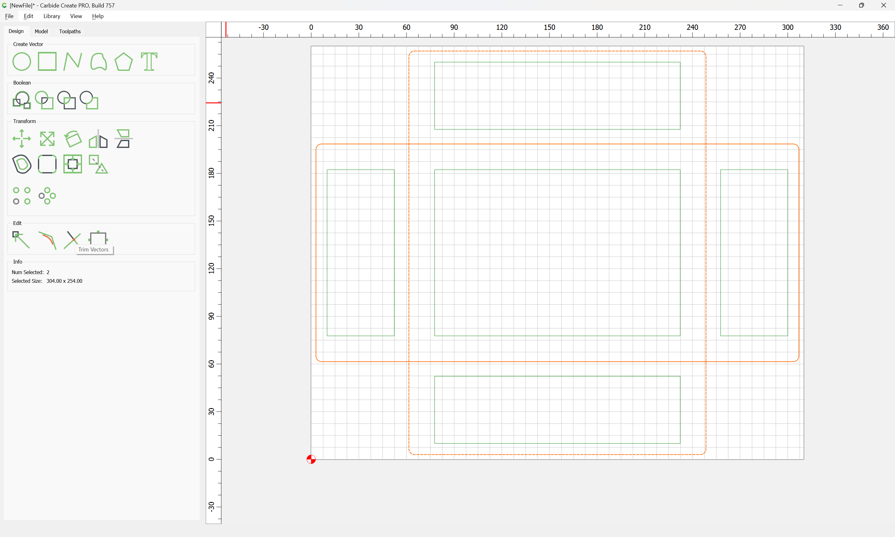
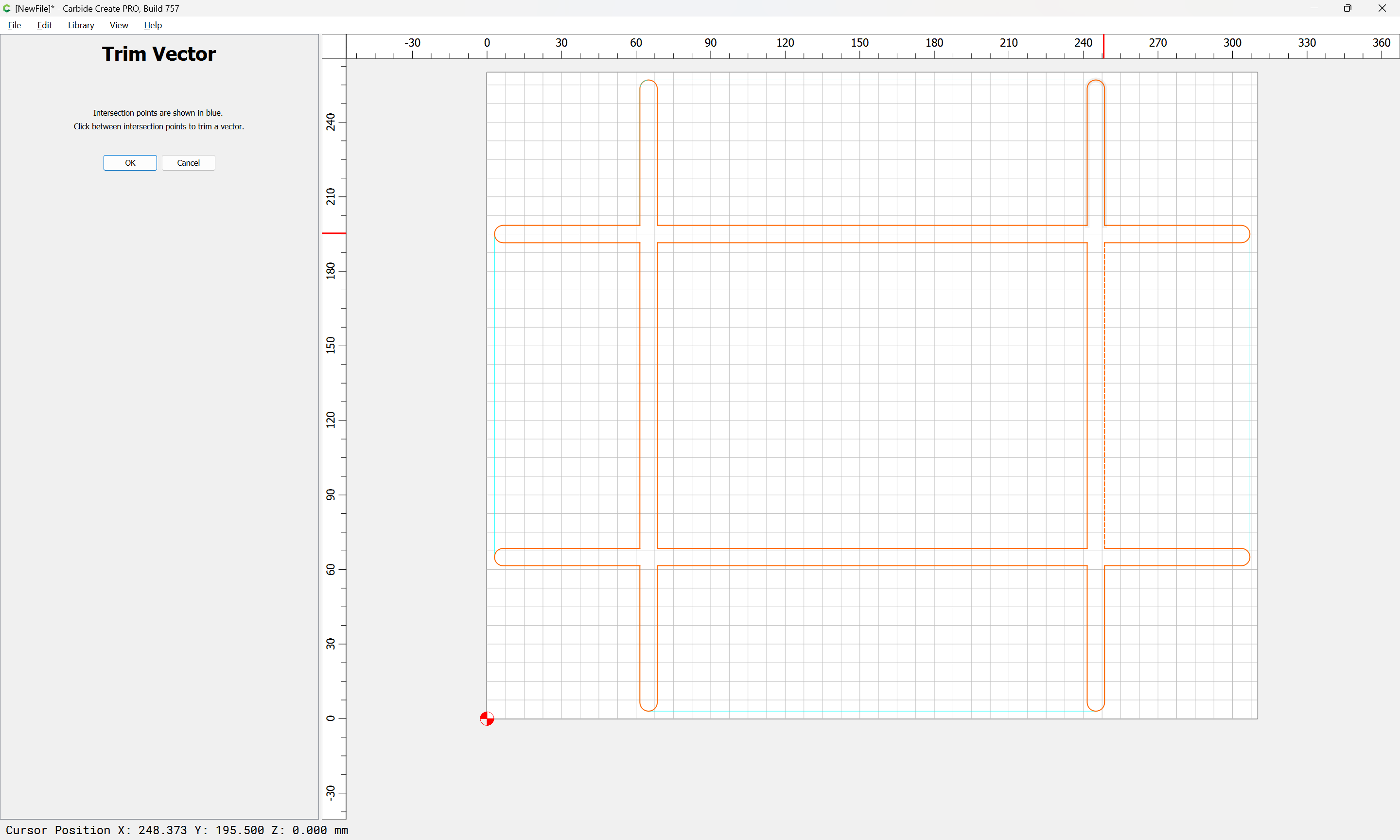
Continue drawing, adjusting dimensions as necessary:
until one arrives at:
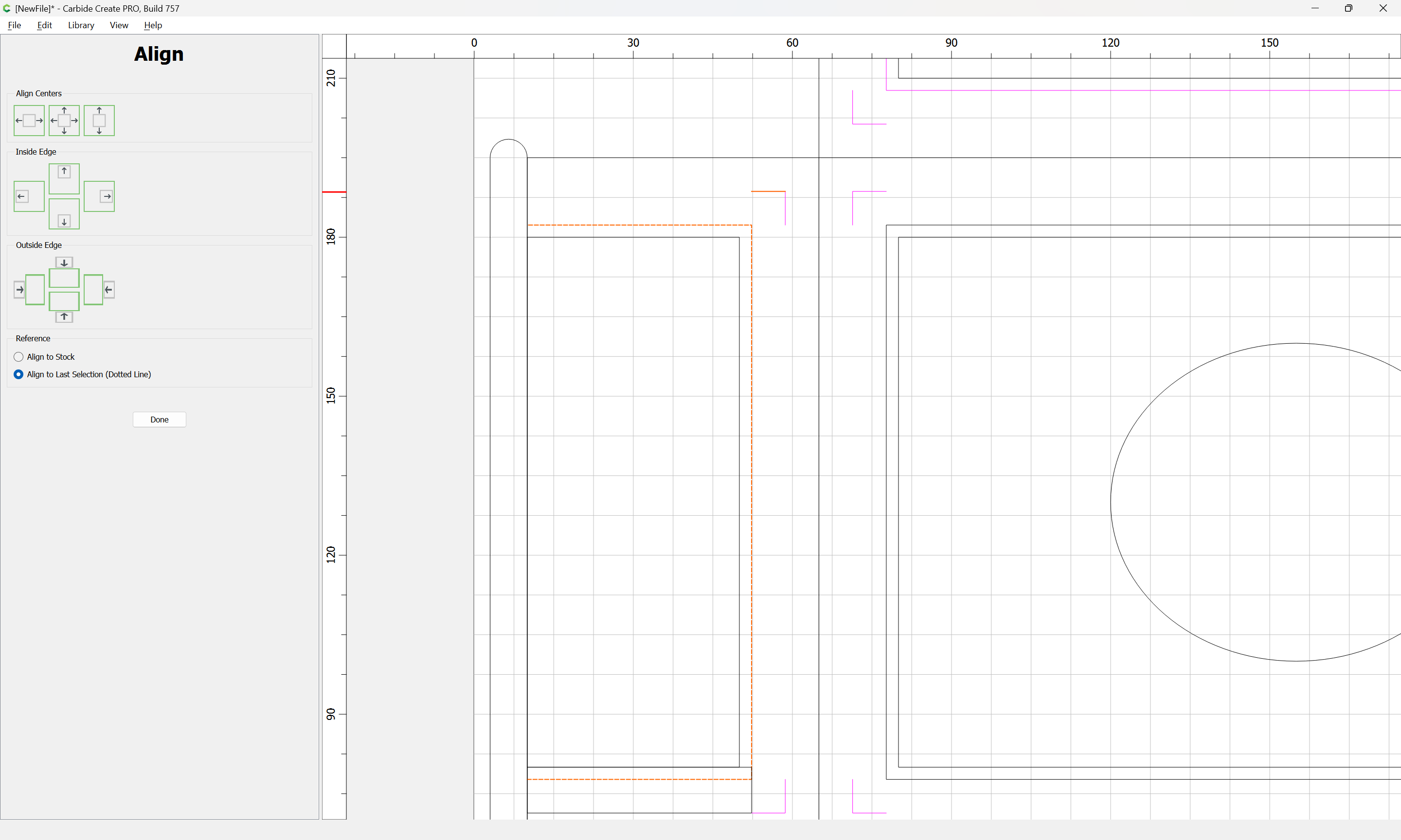
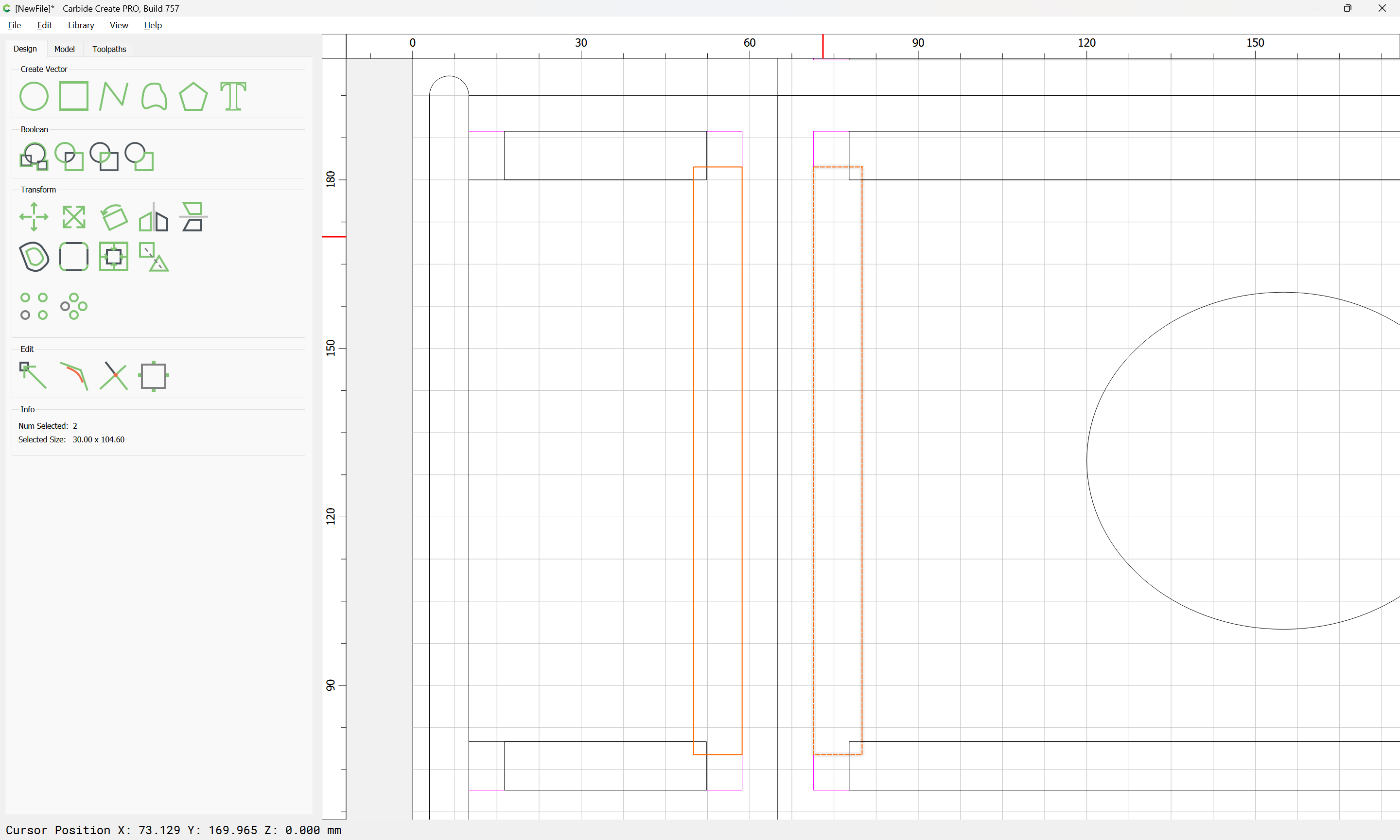
Each of these regions will need to be divided into matching positive/negative versions w/ an equal number of joints/recesses for each pair.
We will also want to overcut on the interior so as to ensure that the parts mesh as expected. This is most easily seen on a matching pair which are aligned:
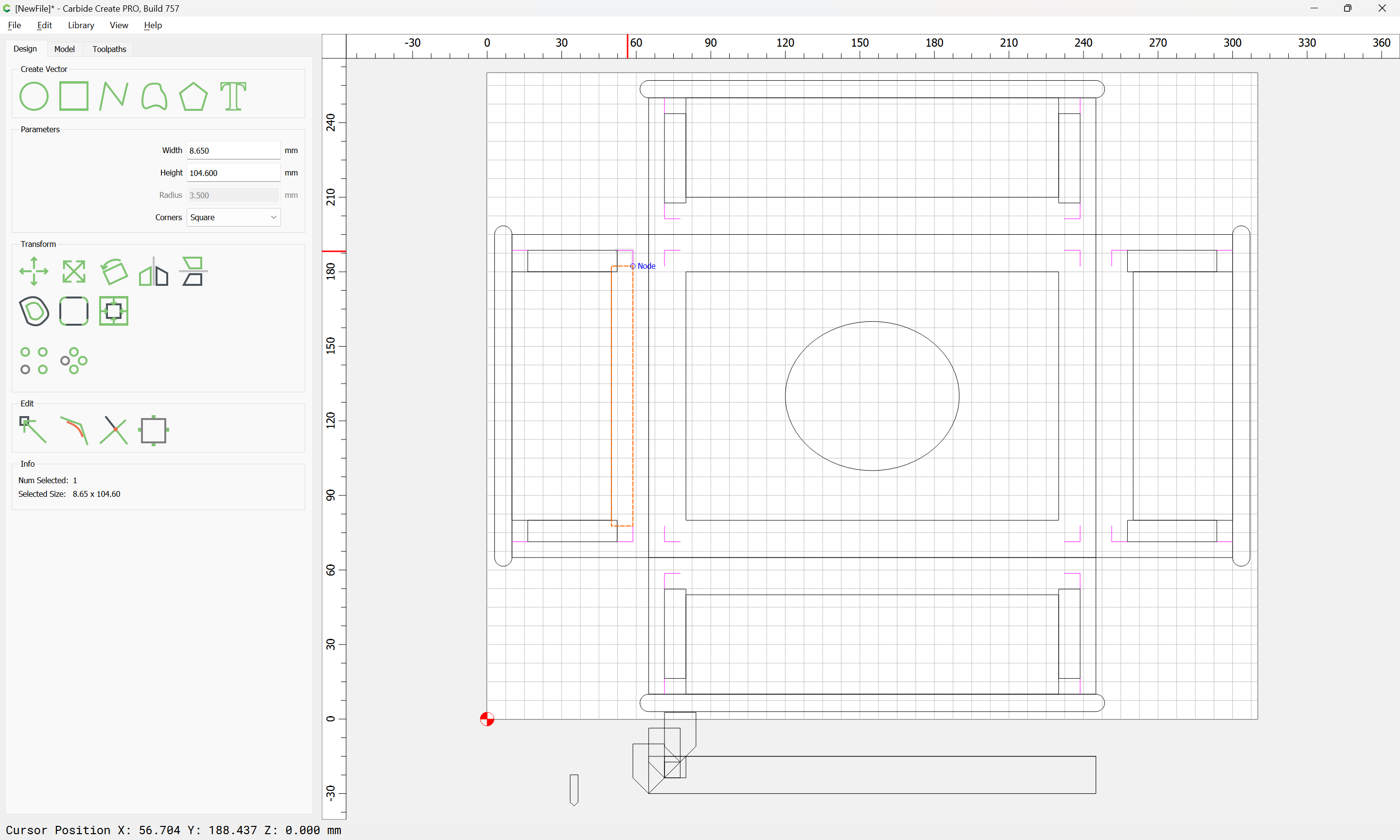
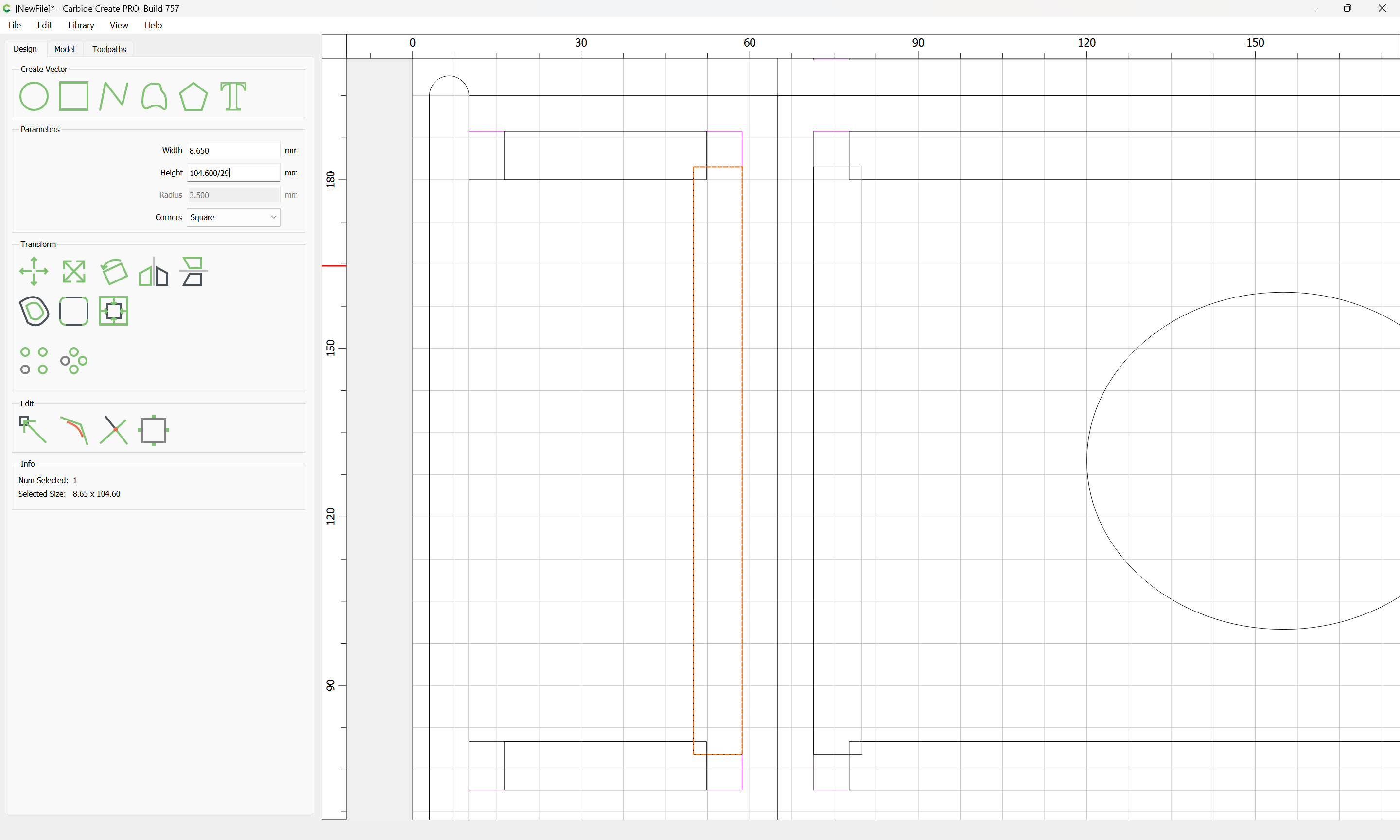
but first, we need to do a bit of math to determine the dimensions of the joint/matching recess. We will use a #102 tool, so the base dimension is 3.175mm, but to ensure that we don’t have rounding issues, we will increase this to 3.5mm and then divide:
104.6 / 3.5 == 29.8857143
Since we want an odd number, we round down and re-do the division:
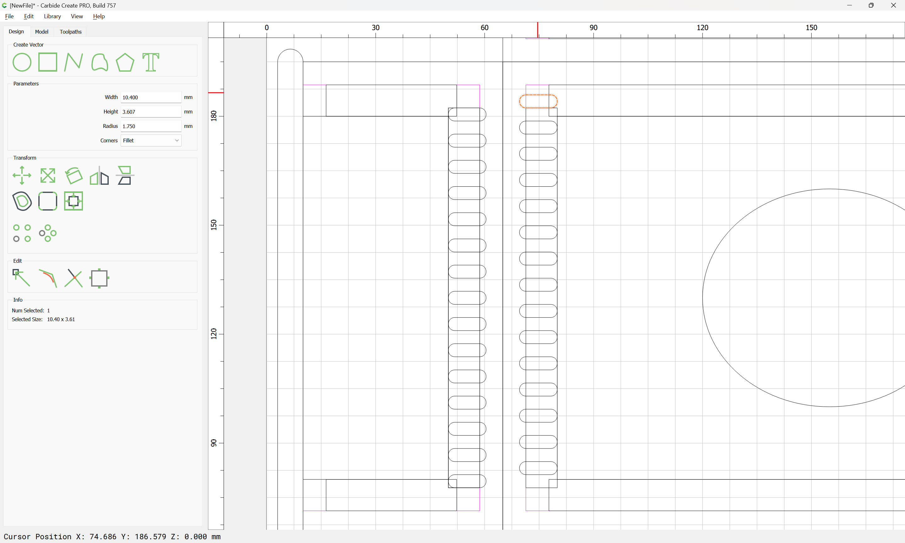
104.6 / 29 == 3.60689655
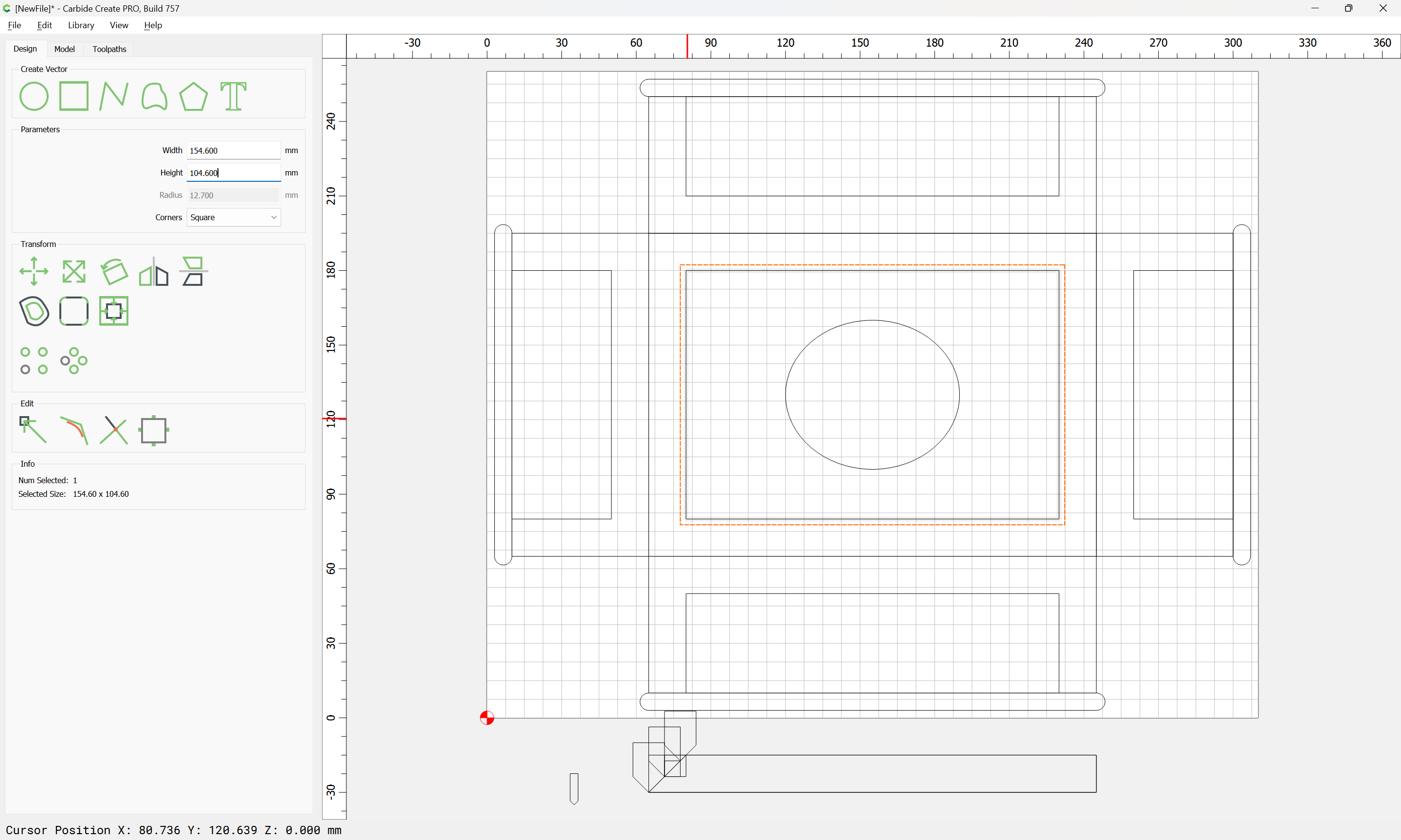
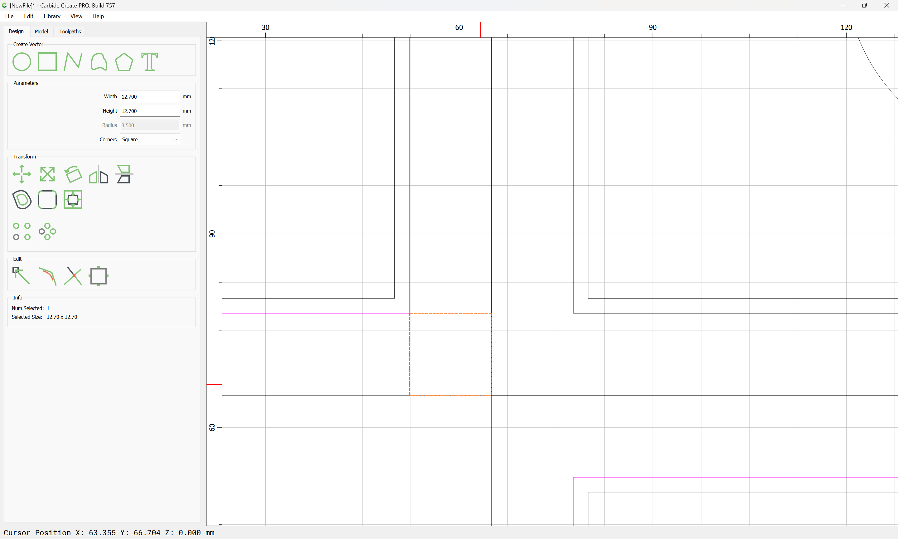
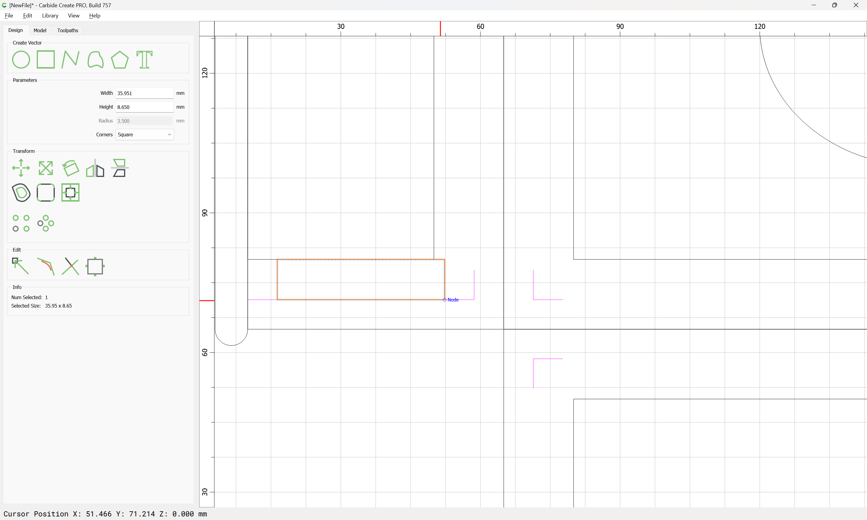
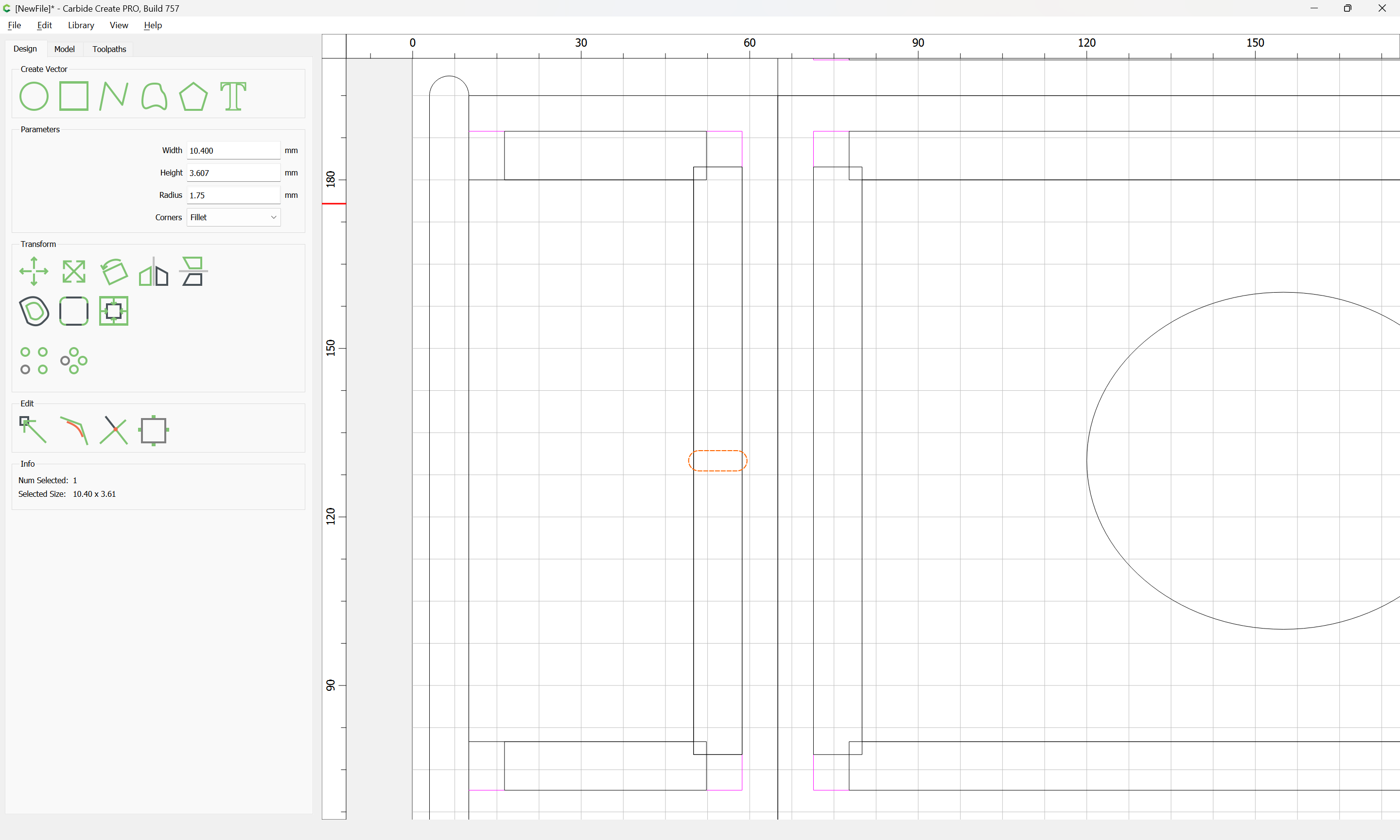
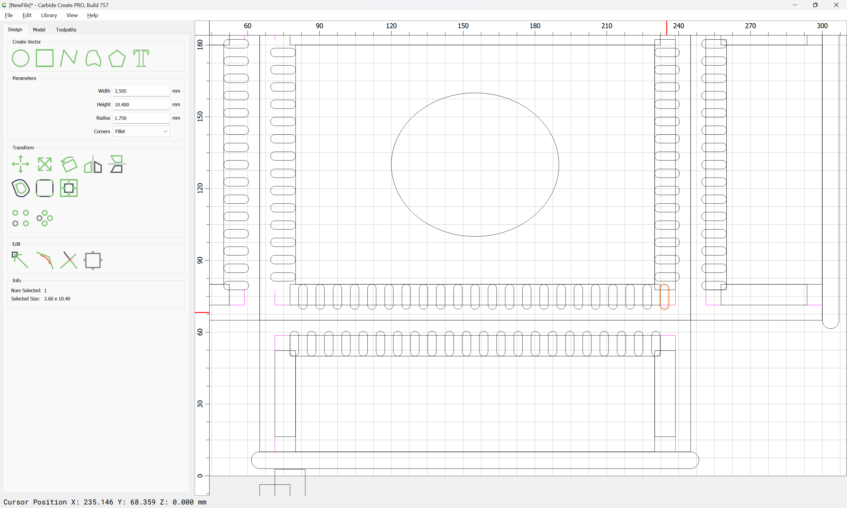
though this can be directly in Carbide Create using a duplicate of one of the placeholder rectangles:

We want it to project 1.75mm in towards the outside of the joint:
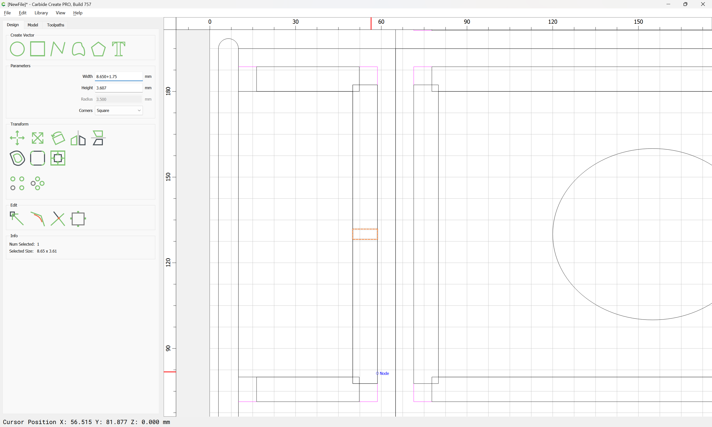
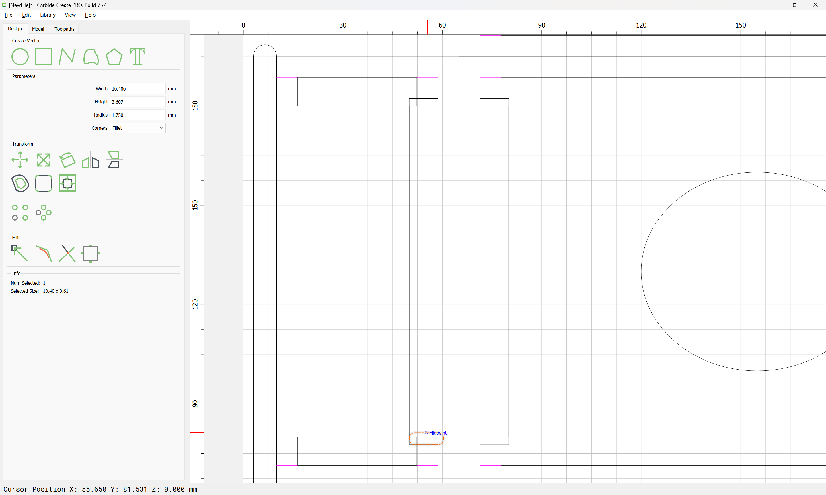
and to have a matching radius:
which then allows it to be snapped in place:
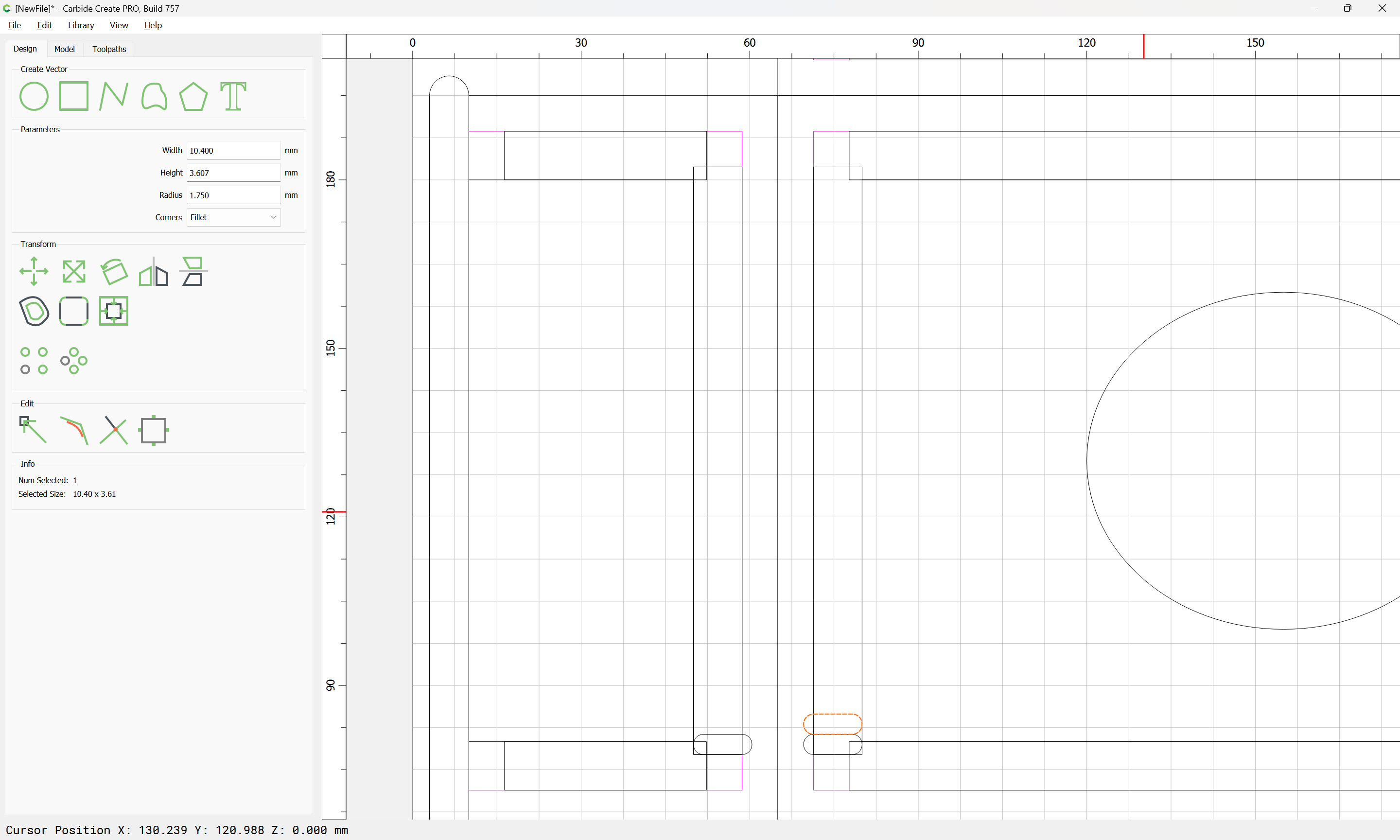
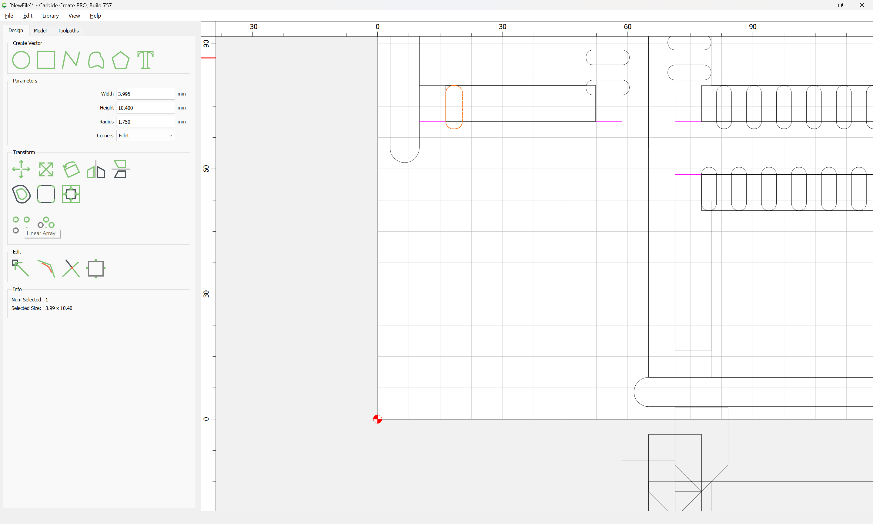
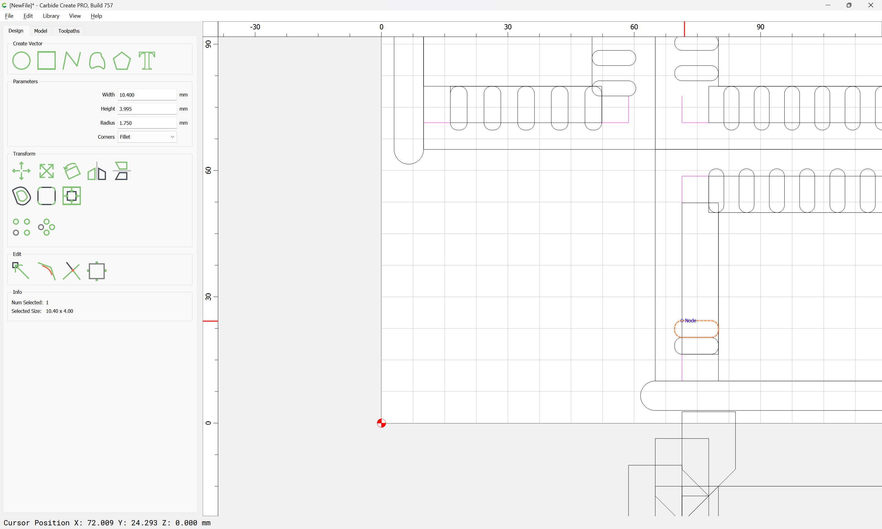
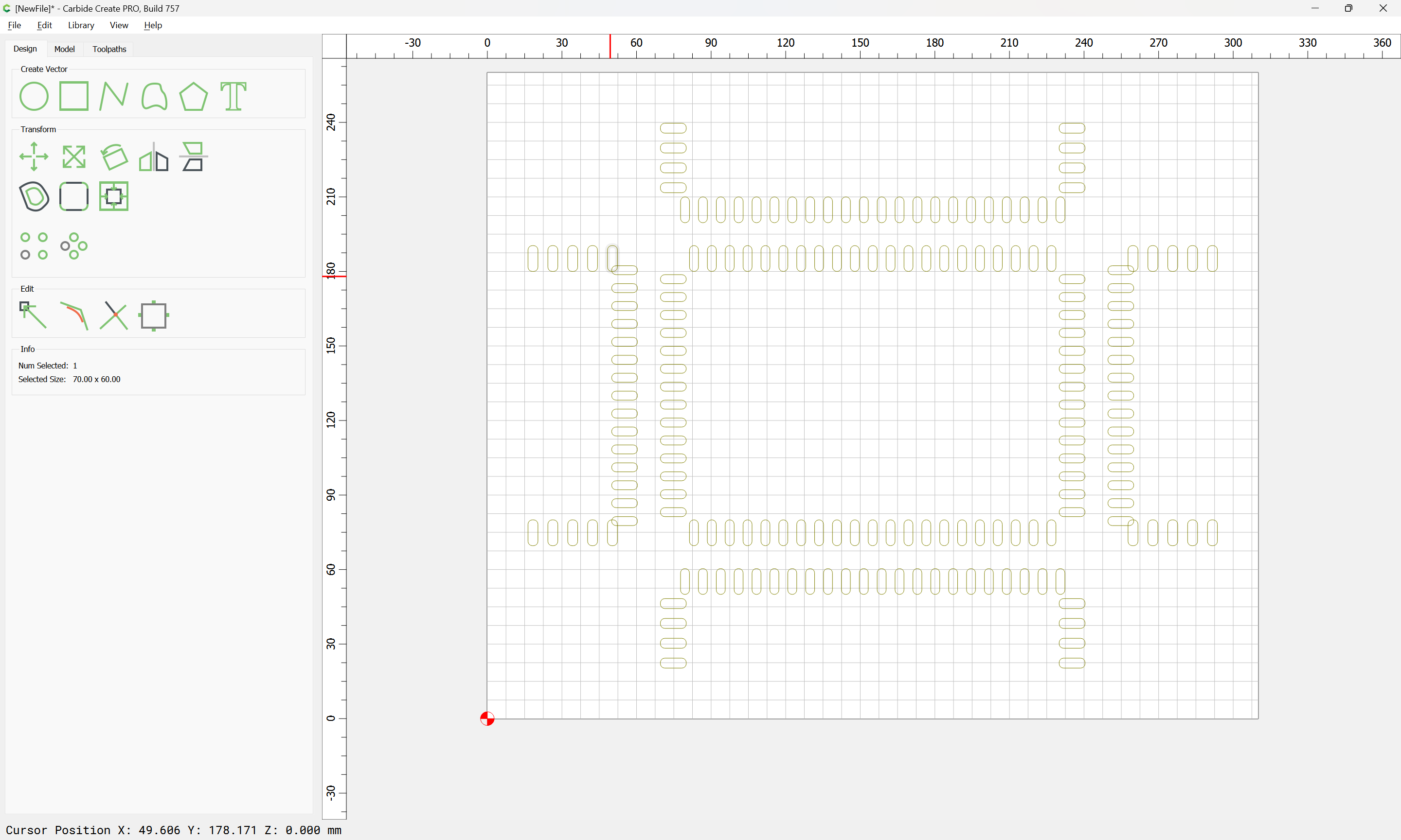
It is now possible to duplicate it and position the duplicates (one as a placeholder, the other as the matching recess):
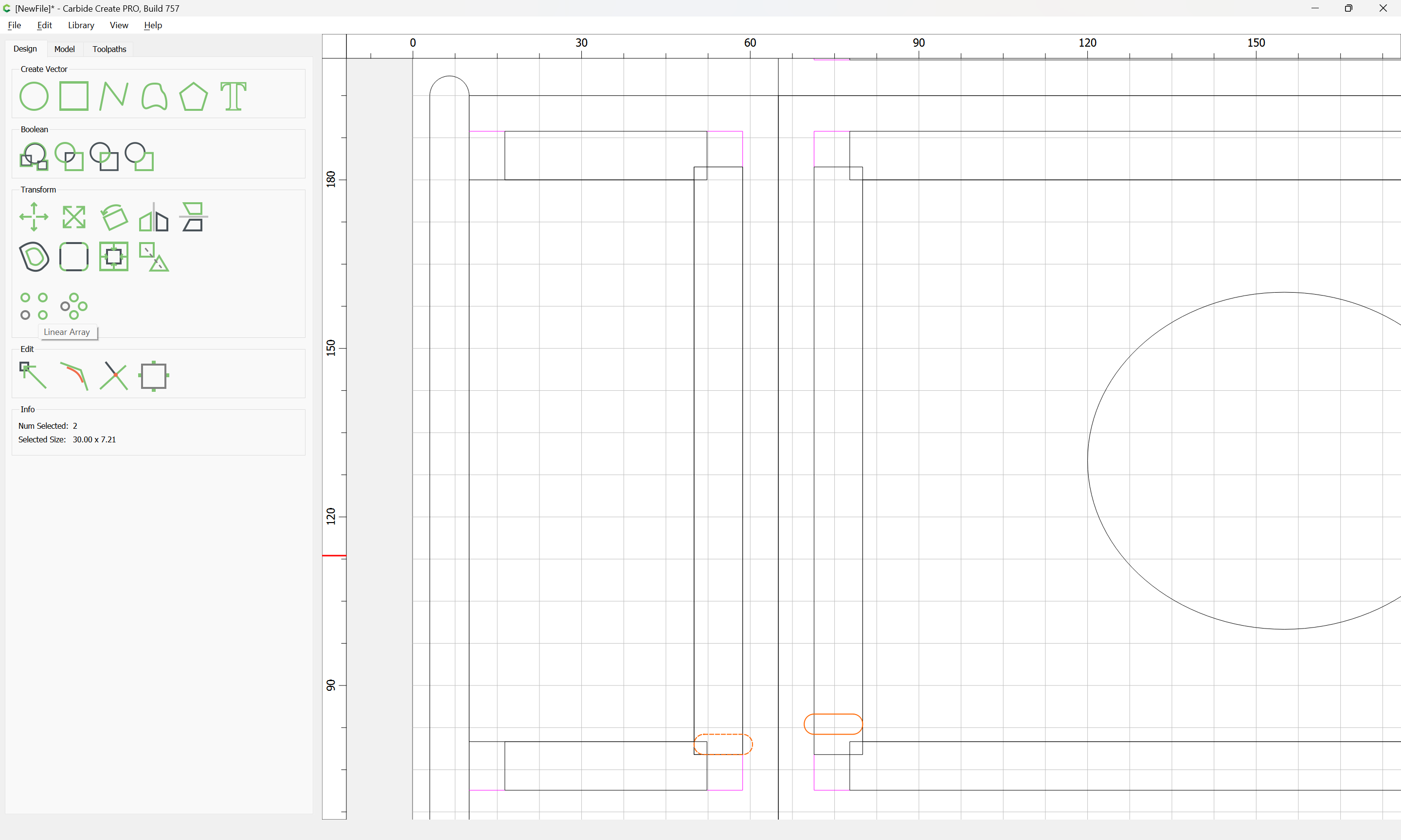
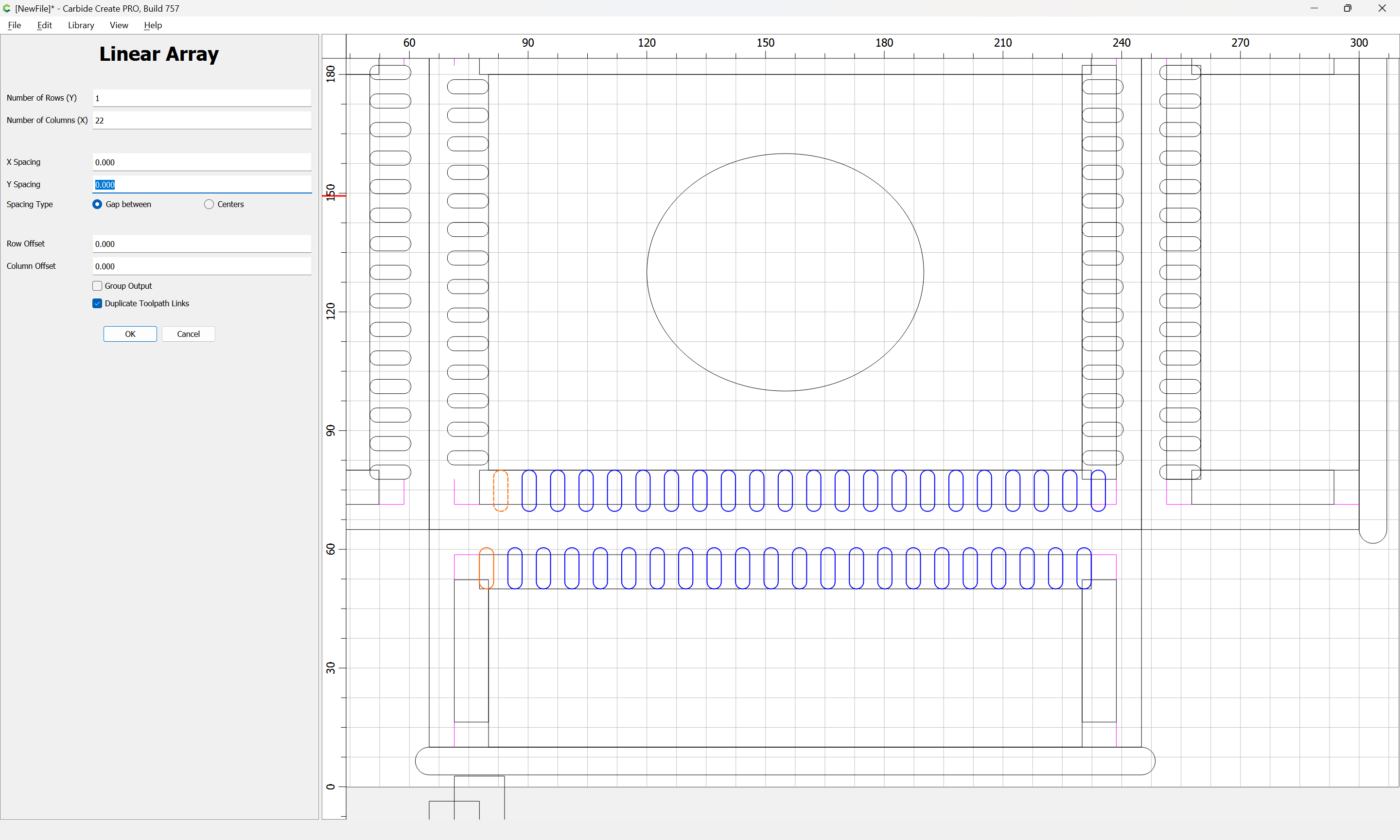
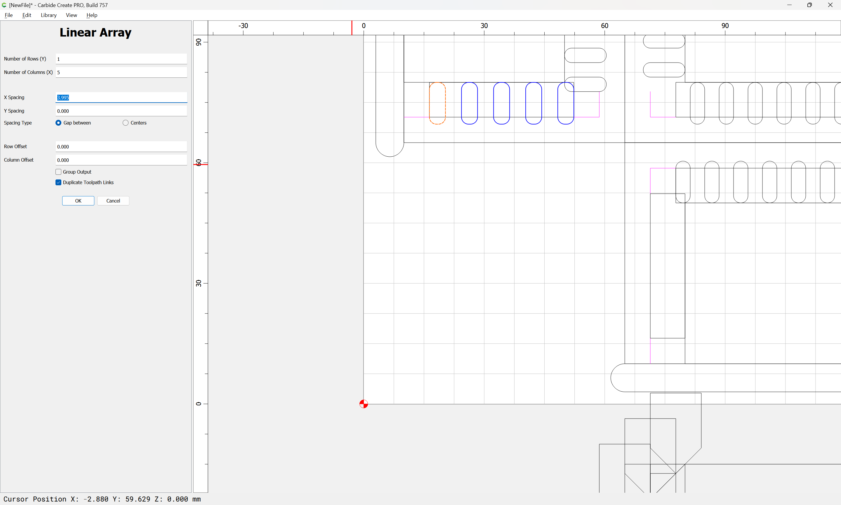
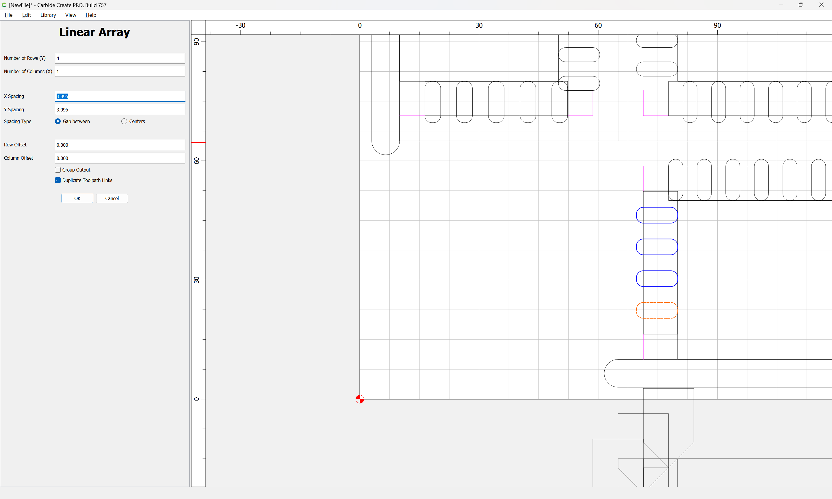
allowing us to use Linear Array to make the needed duplicates:
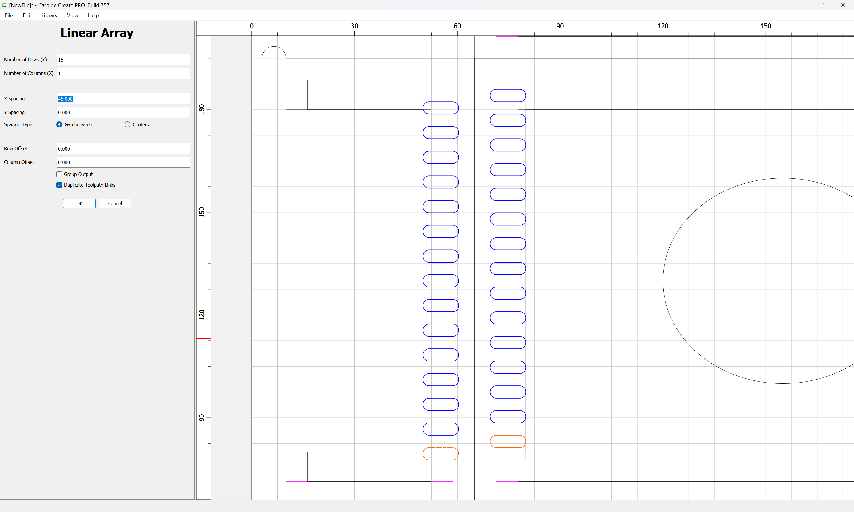
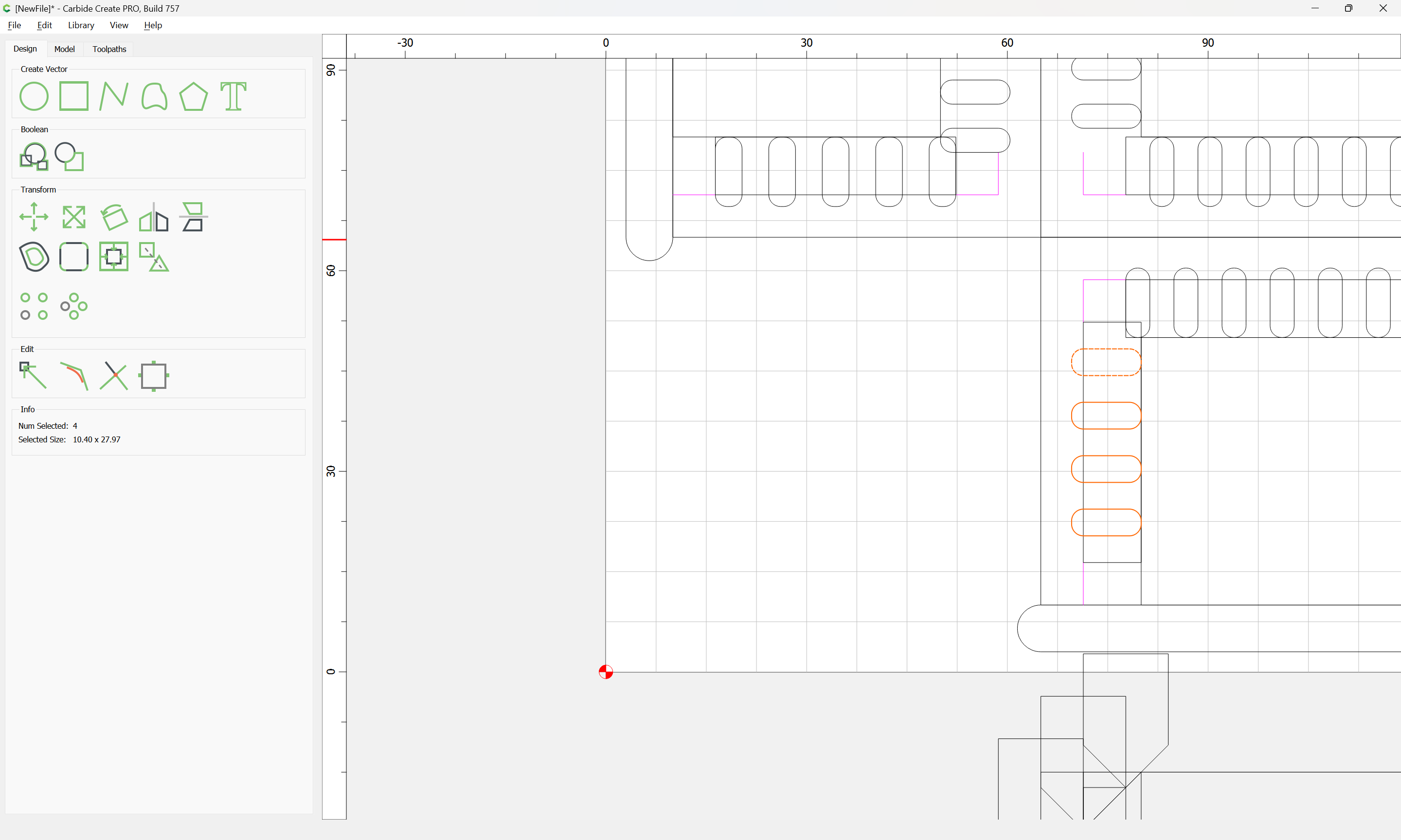
(and one spare which will need to be cleaned up)
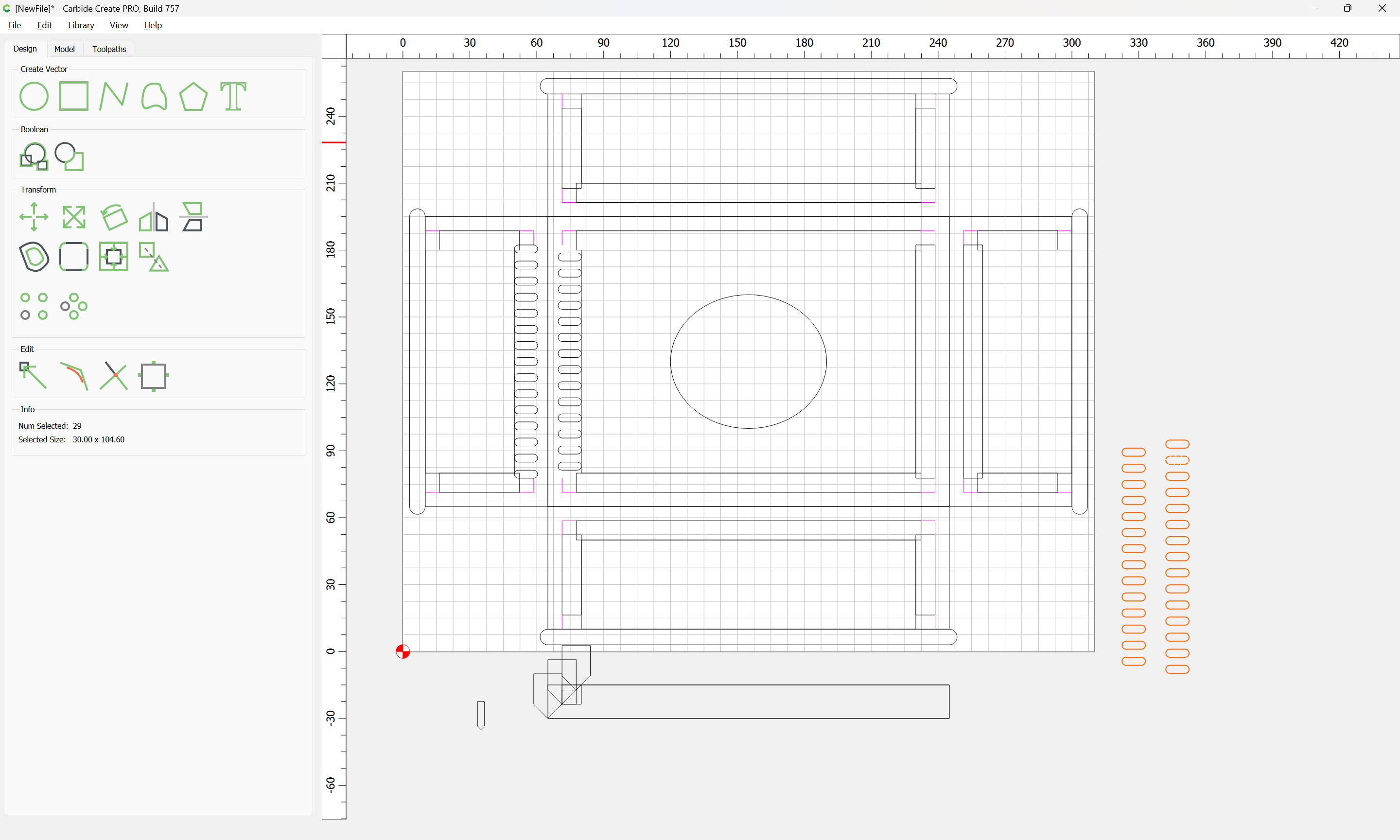
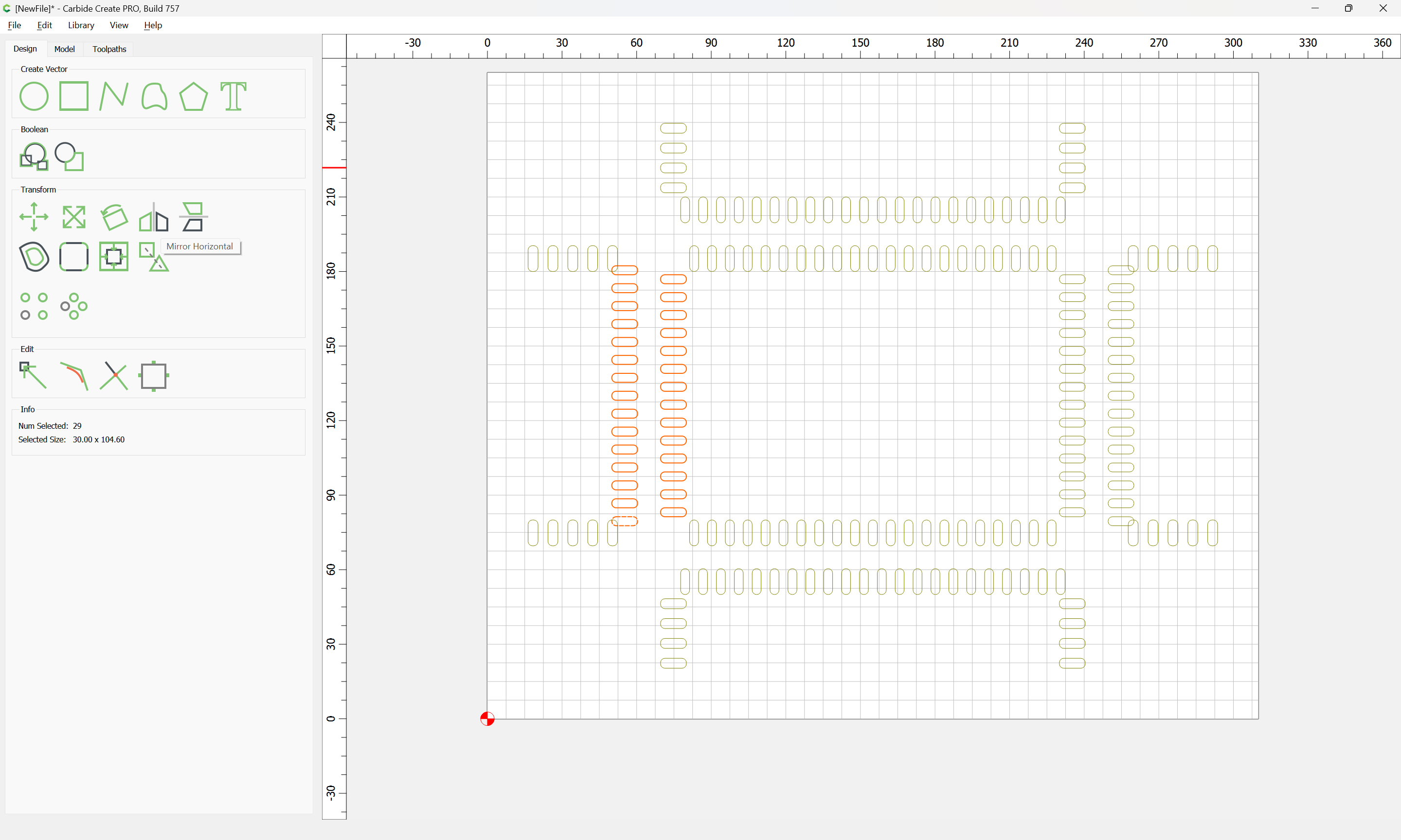
Duplicate this as needed:

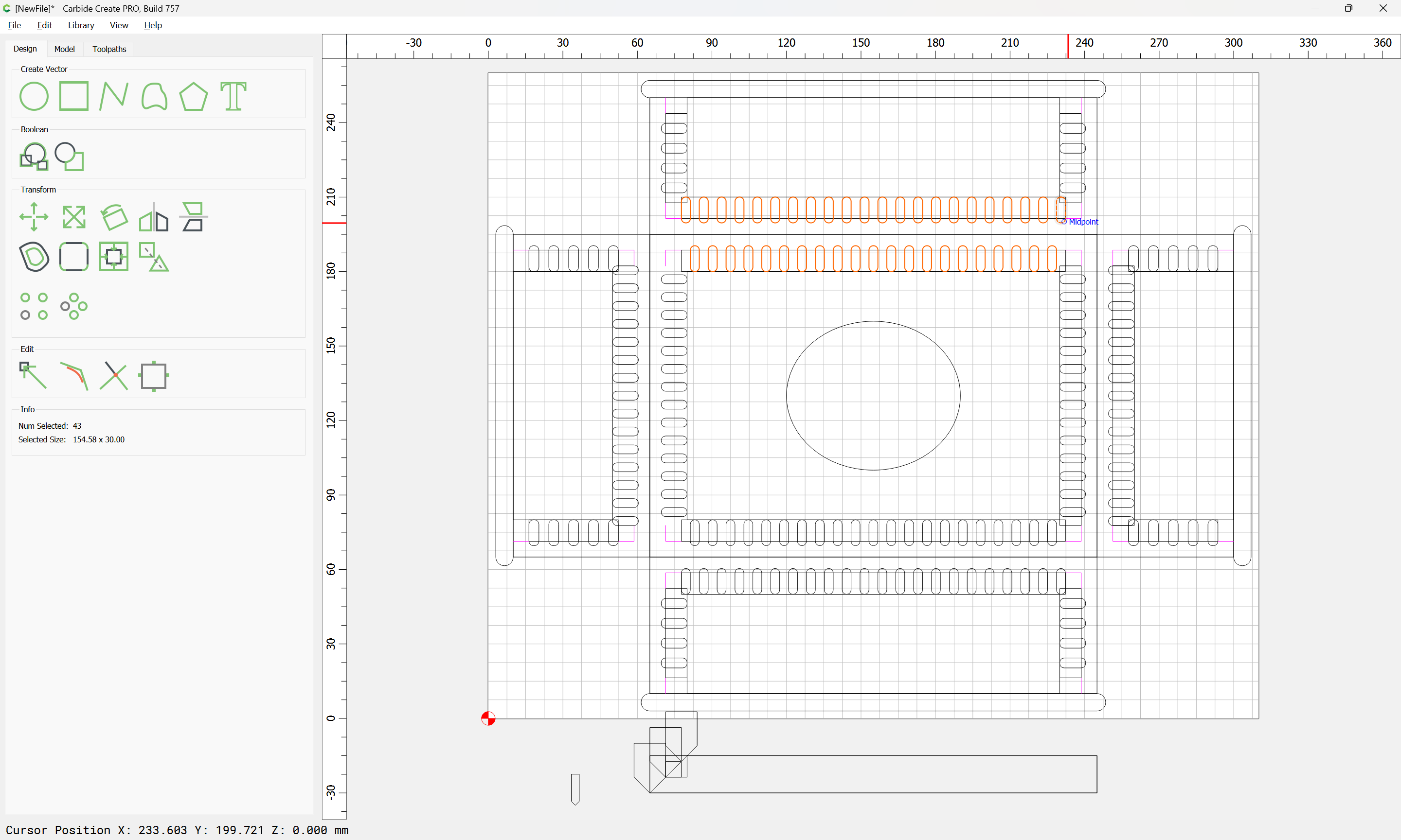
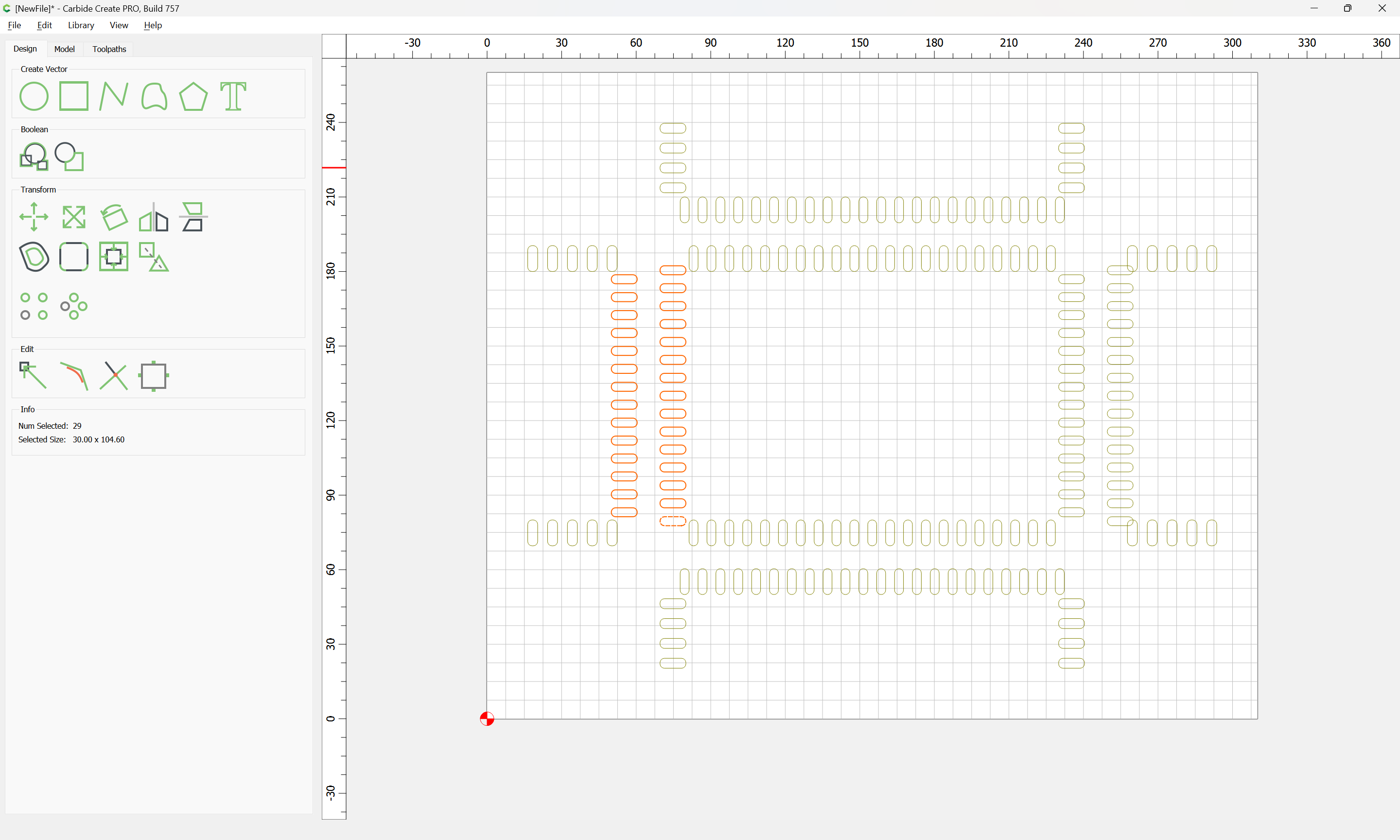
Mirror horizontal:
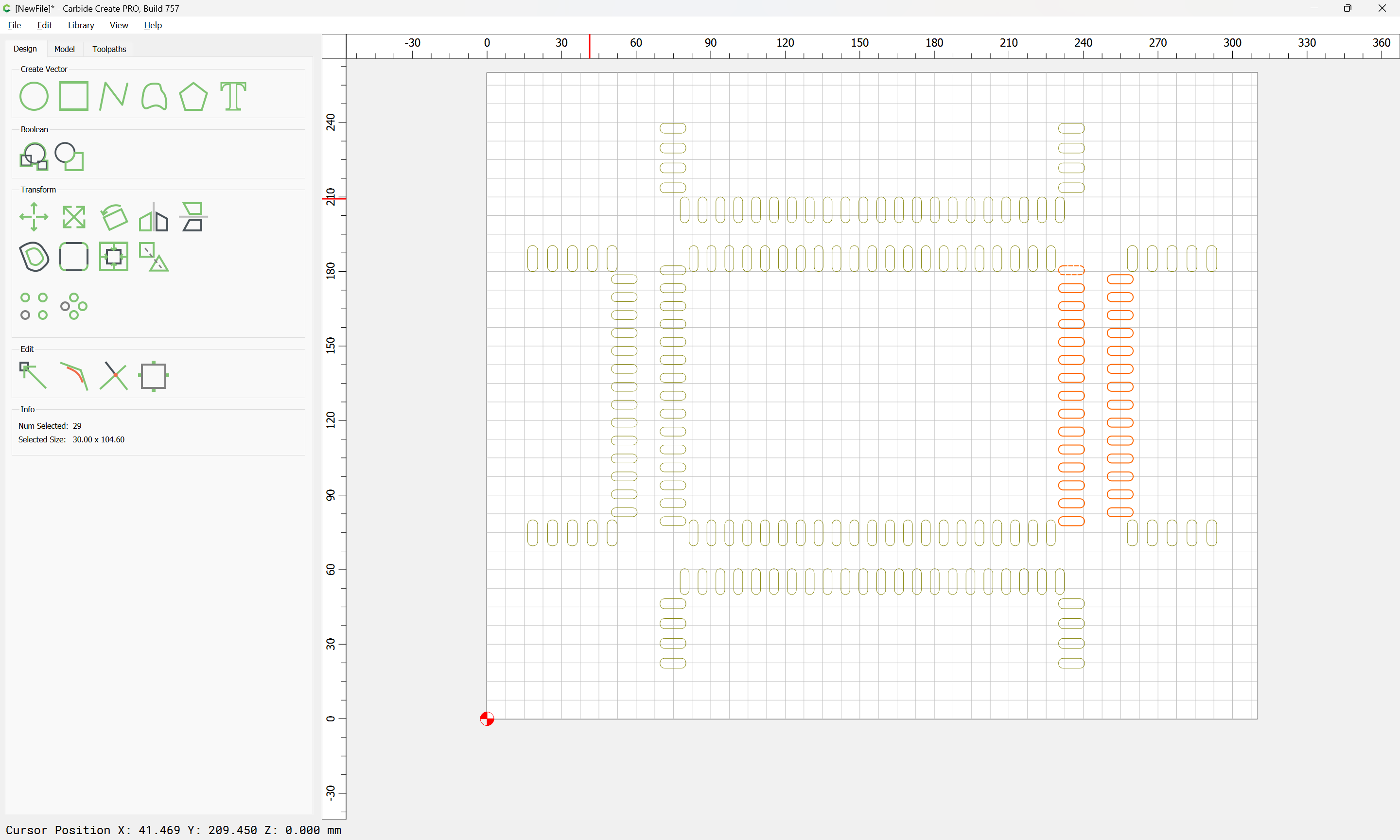
and drag into position:
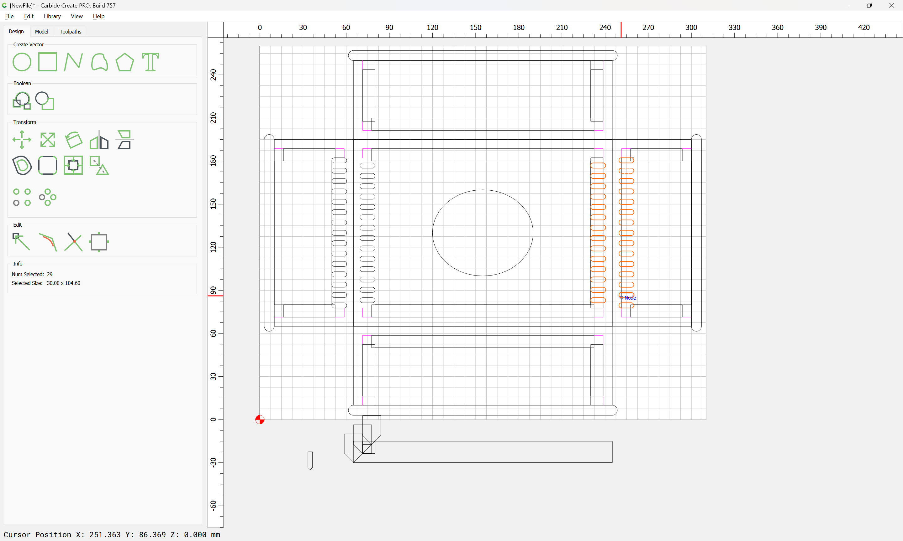
Repeat for the other joints.
1 Like
Ok this is quite a thing! Thank you - it will be good to get the hang of doing one and then probably it gets easier. But this is all done horizontally I assume and results in a nice join.
I assumed I would need a tiny cutter but I have a 102 probably the one that came in the kit
For the joints which are at right angles, one can either do the joinery so that one half is in empty space and then rotate/move it, or do it twice:
arriving at:
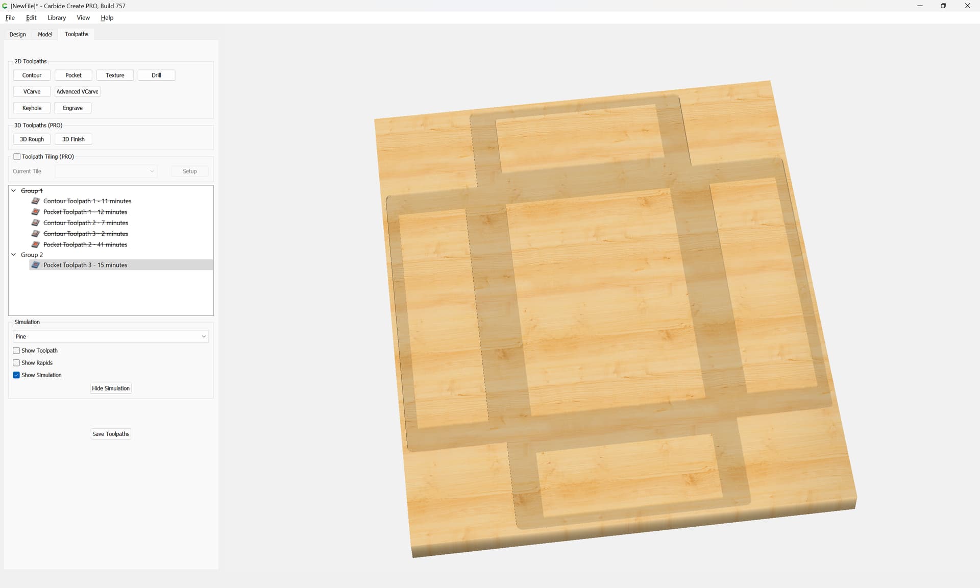
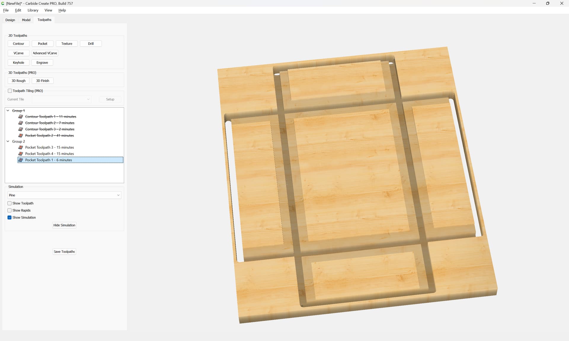
which with toolpaths previews as:
It will be necessary to merge some geometry and add a toolpath to cut the joinery down to the initial V carve level so that they will allow things to fit together.
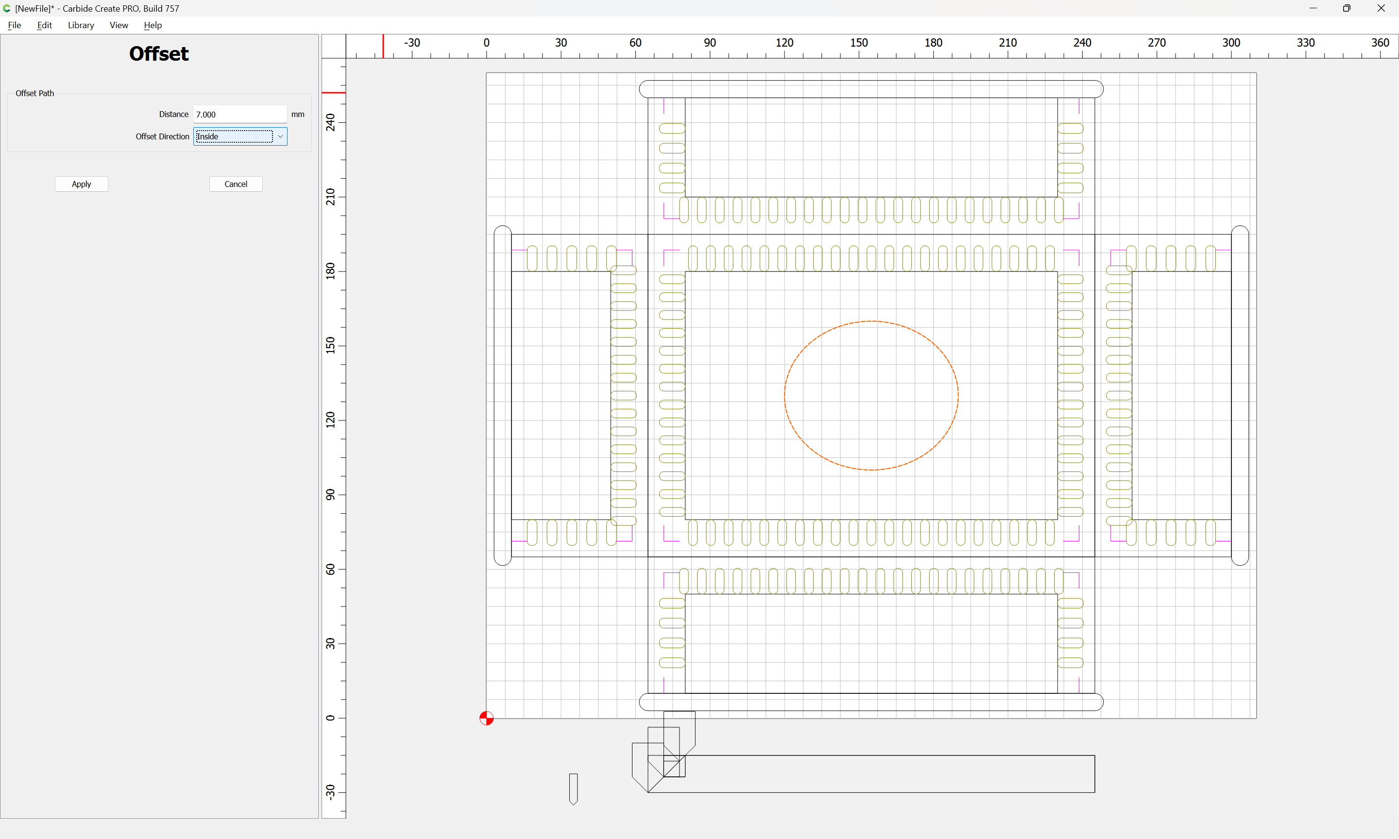
This is a combination of the central channels (for the V carving tool) and an exclusion based on the 2.3mm deep V cut, but is most readily visualized as an offset and inset from the parts:
Just close the open geometry:
Then it is simply necessary to arrange the toolpaths so that things cut optimally, and to add geometry to facilitate that.
Yes, this is all designed to be cut flat — while I’ve done a fair bit of work on doing traditional joinery on the machines, I mislike it because:
- it requires a minimum of 3 setups:
- cut parts to size (and internal features)
- clamp all four boards in a vertical feature and cut two corners of the joinery
- rotate all four boards, re-clamp, and then cut the other two corners
I’ll go over the needed tooling and the requirements for it presently.
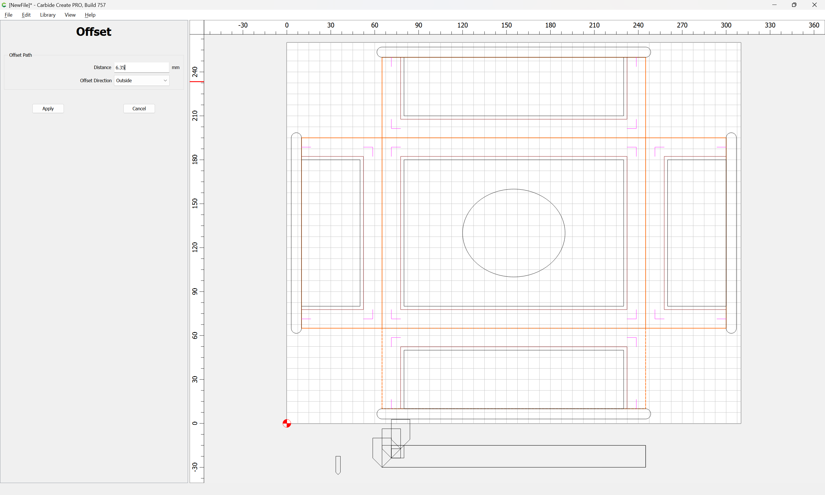
The first toolpath is cutting down to the tops of the joinery — it is an outer surrounding toolpath made by offsetting the parts a bit more than the endmill diameter:
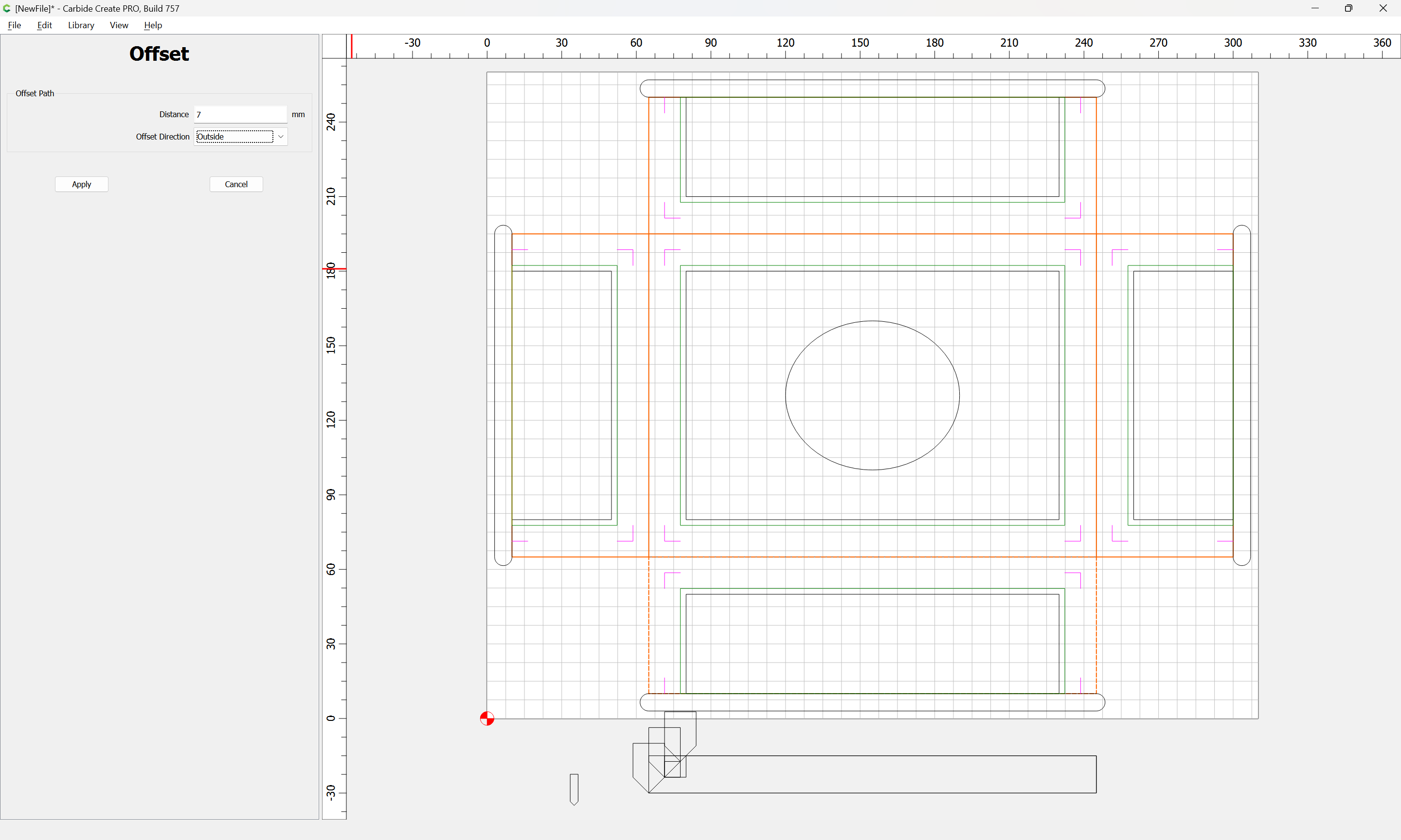
and closing the initial V endmill geometry as noted before:
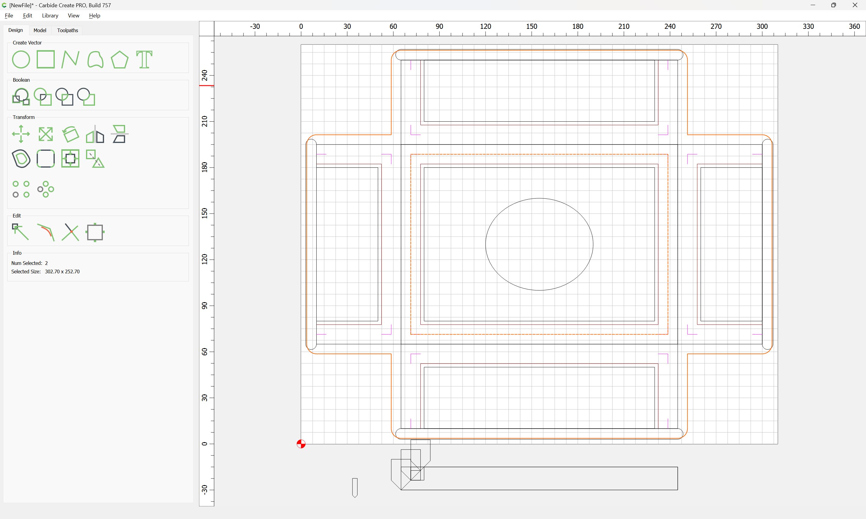
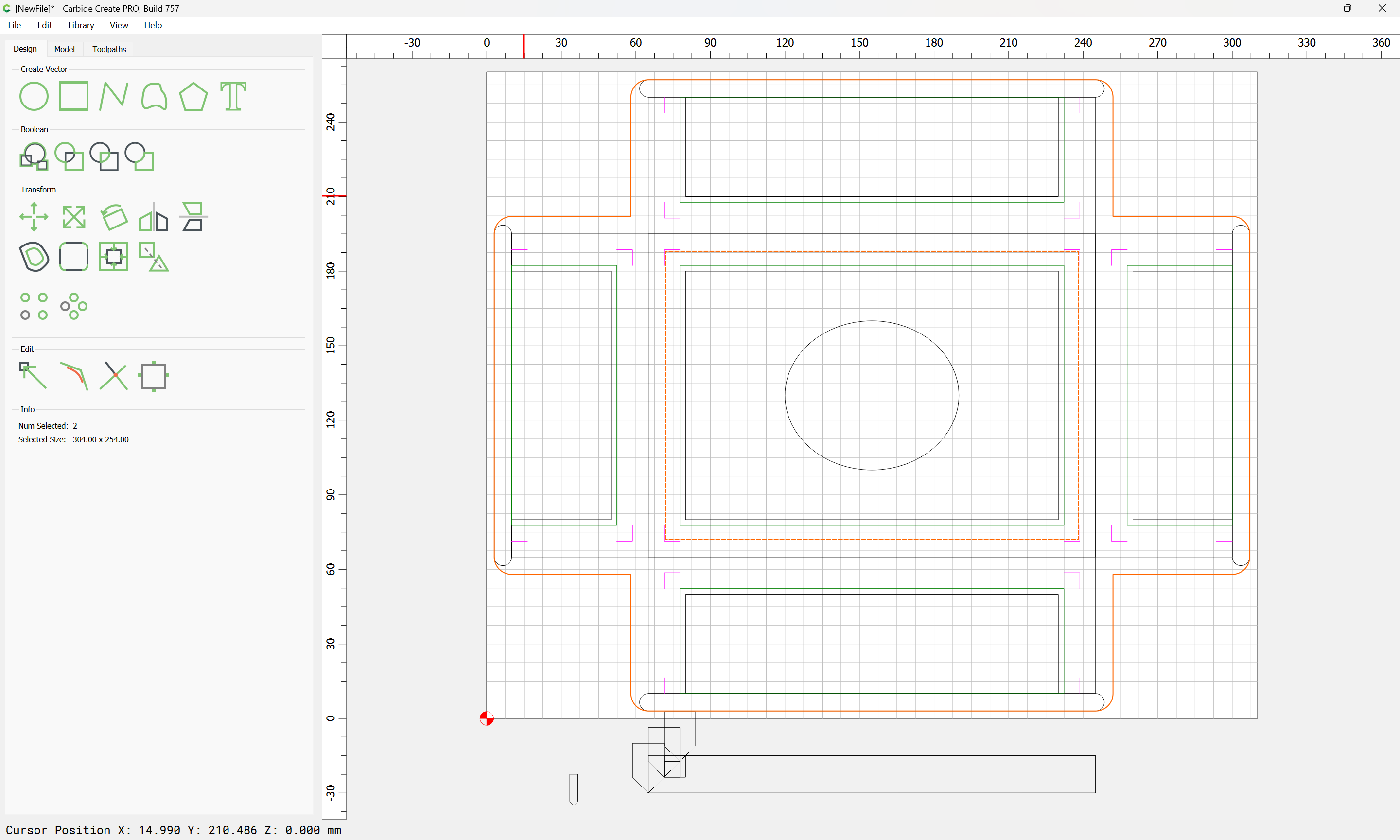
Arguably, a more concise geometry would be a pair of overlapping, rounded rectangles:
OK
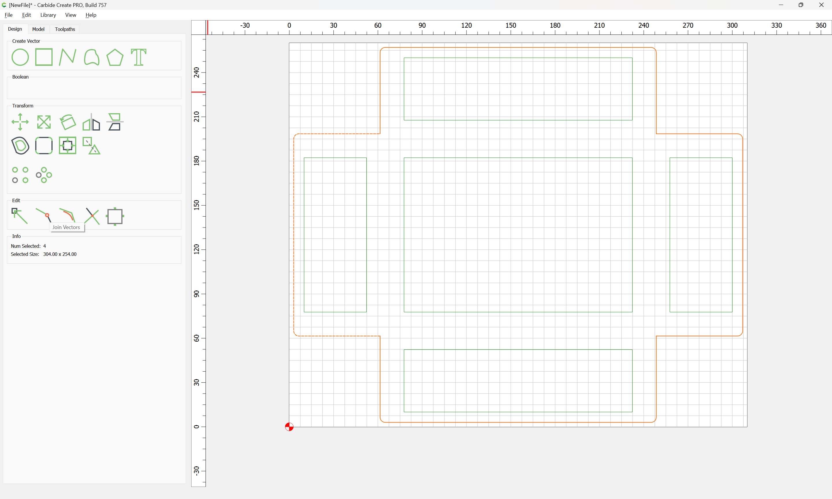
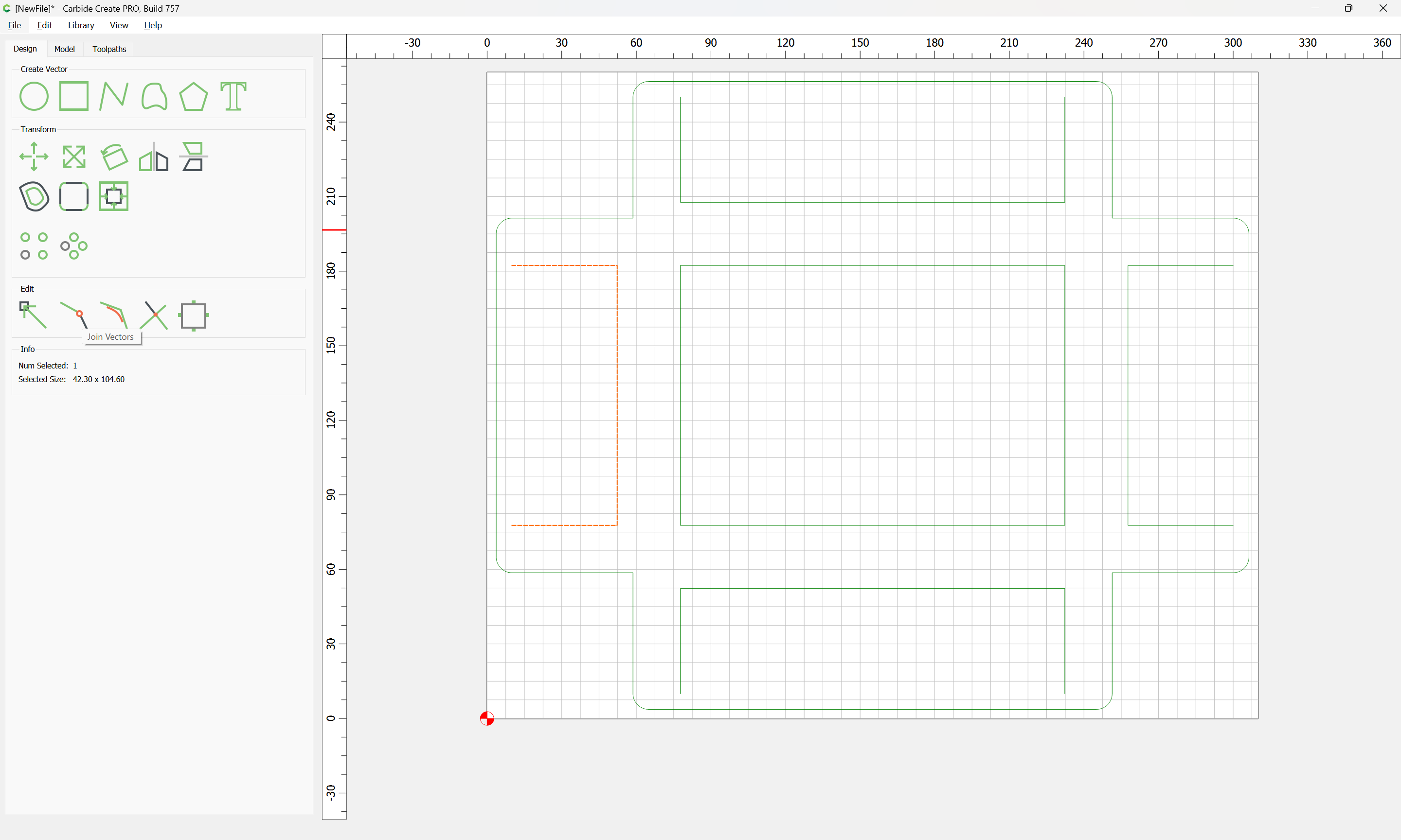
Join Vectors
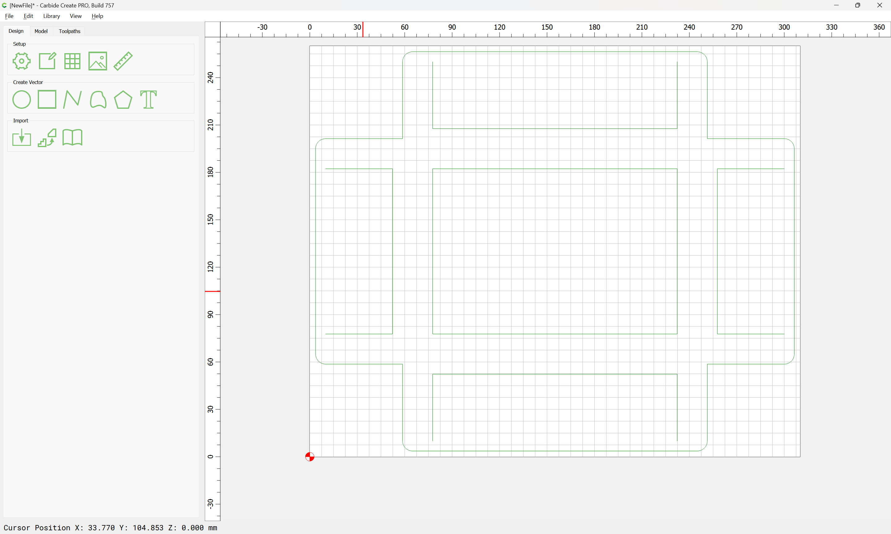
The next cut is the surrounding geometry, plus the central channels where the V endmill will cut:

and copy the perimeter geometry to a new layer:
and draw in geometry which defines what needs to be kept based on these intersections:
Adjust based on the part geometry:
Delete what is no longer needed:
and create a toolpath which starts at the bottom of the previous one and cuts down to the top of where the V endmill cuts.
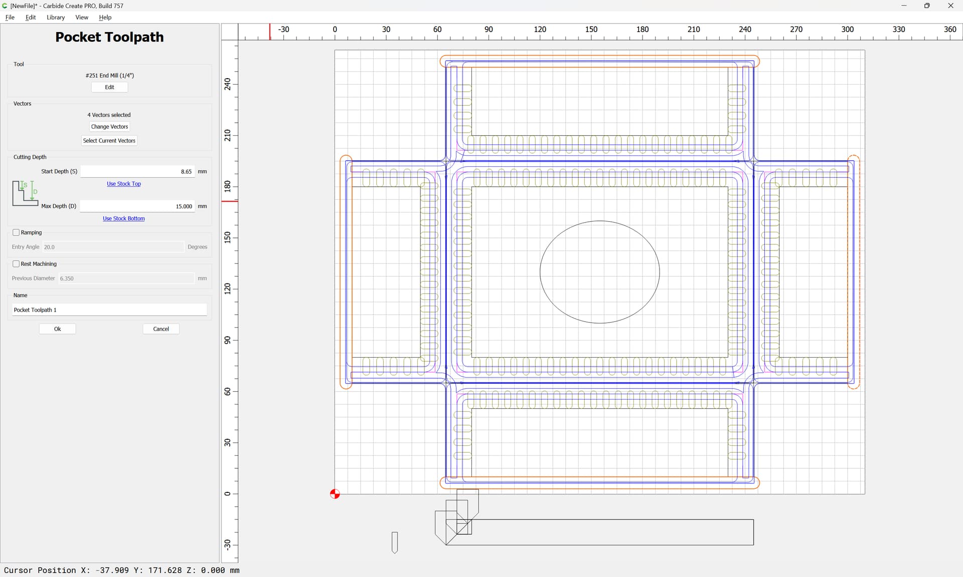
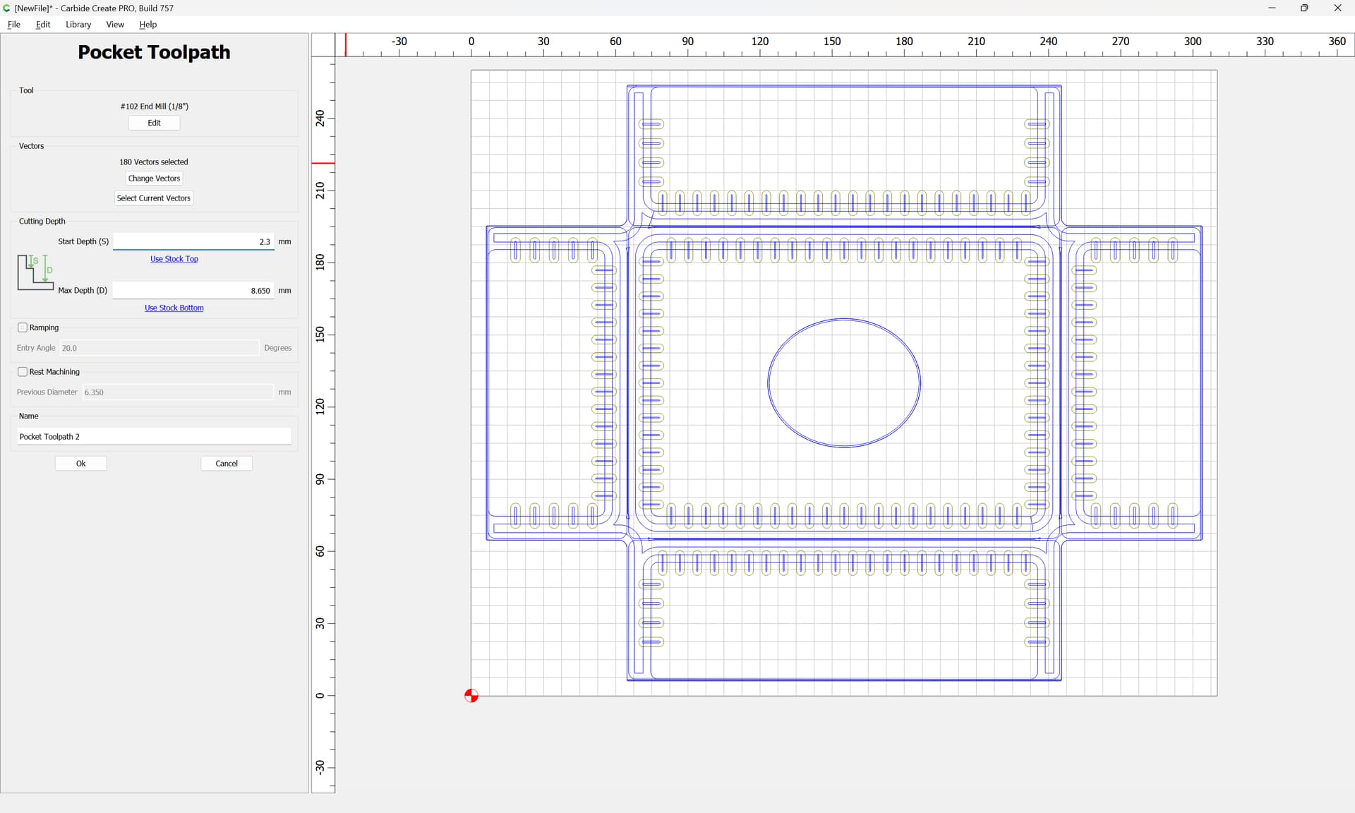
It would also be appropriate to cut the oval out using this tool:
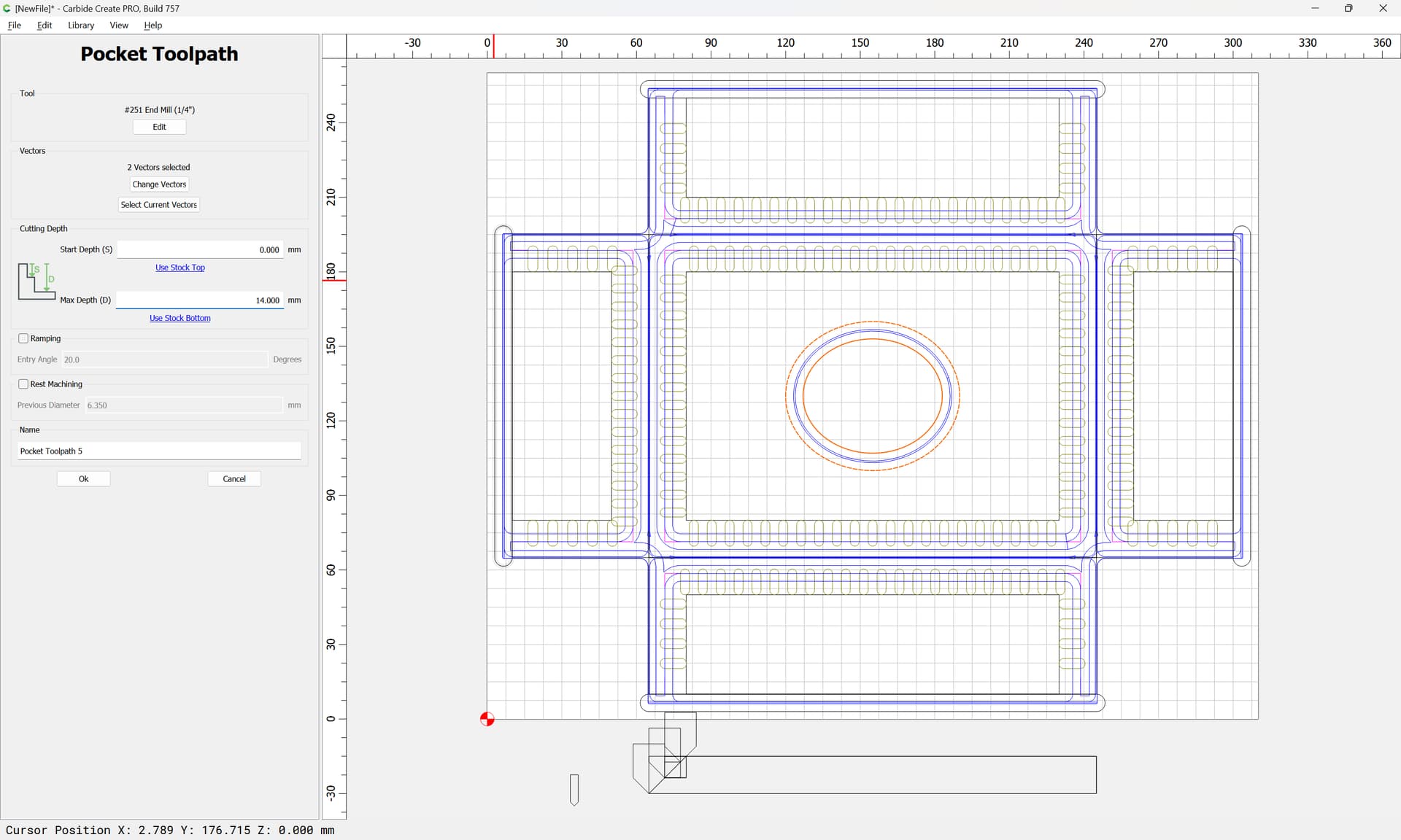
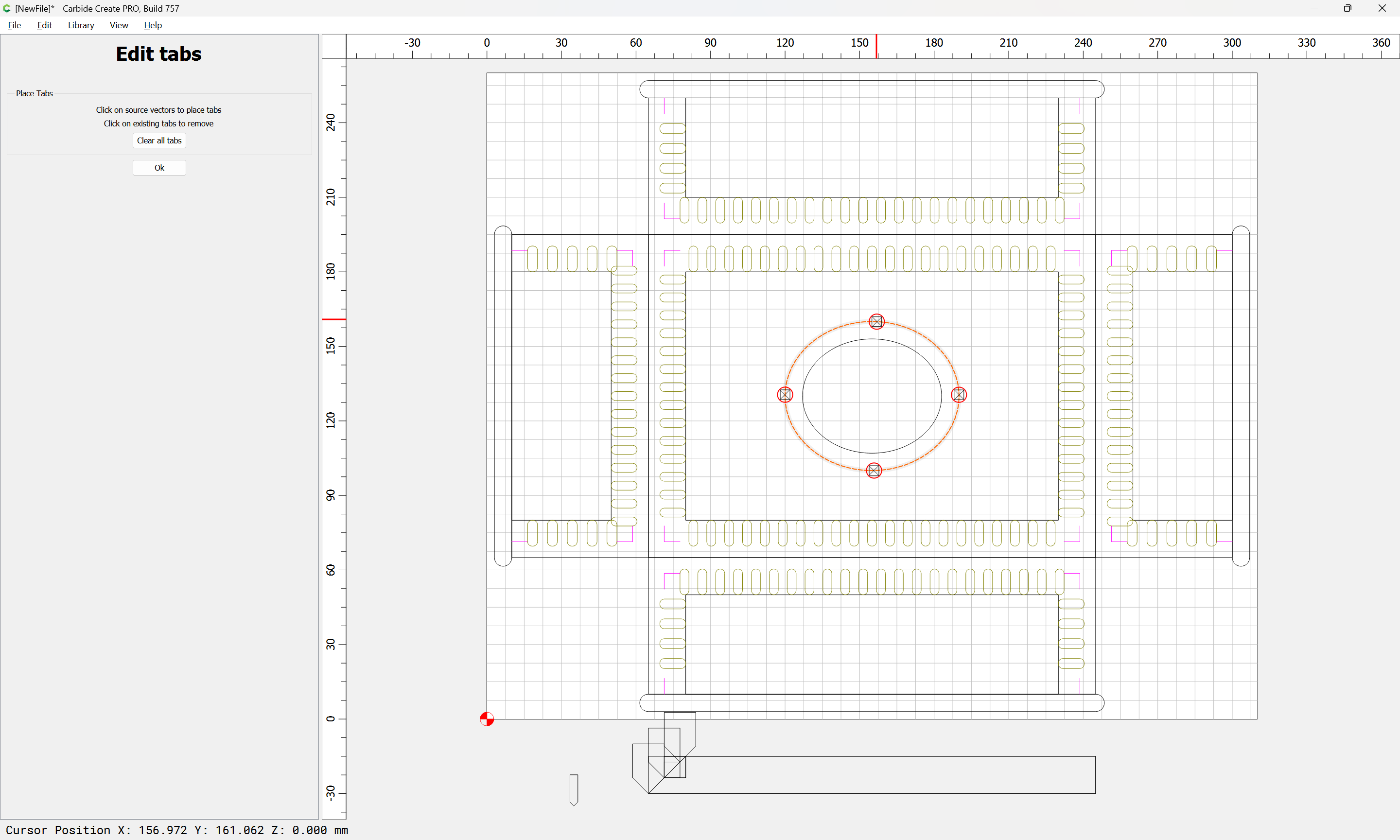
Do not cut the entire oval out — cut down only to tab height with the pocket, then add tabs:
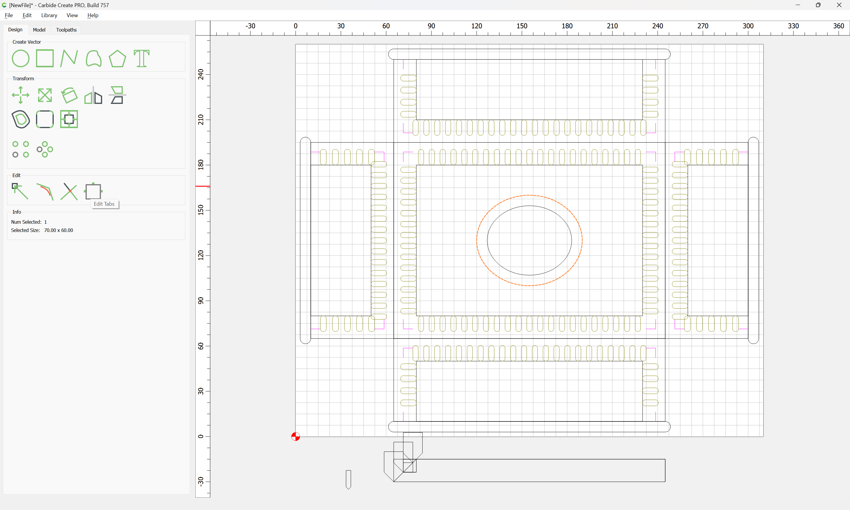
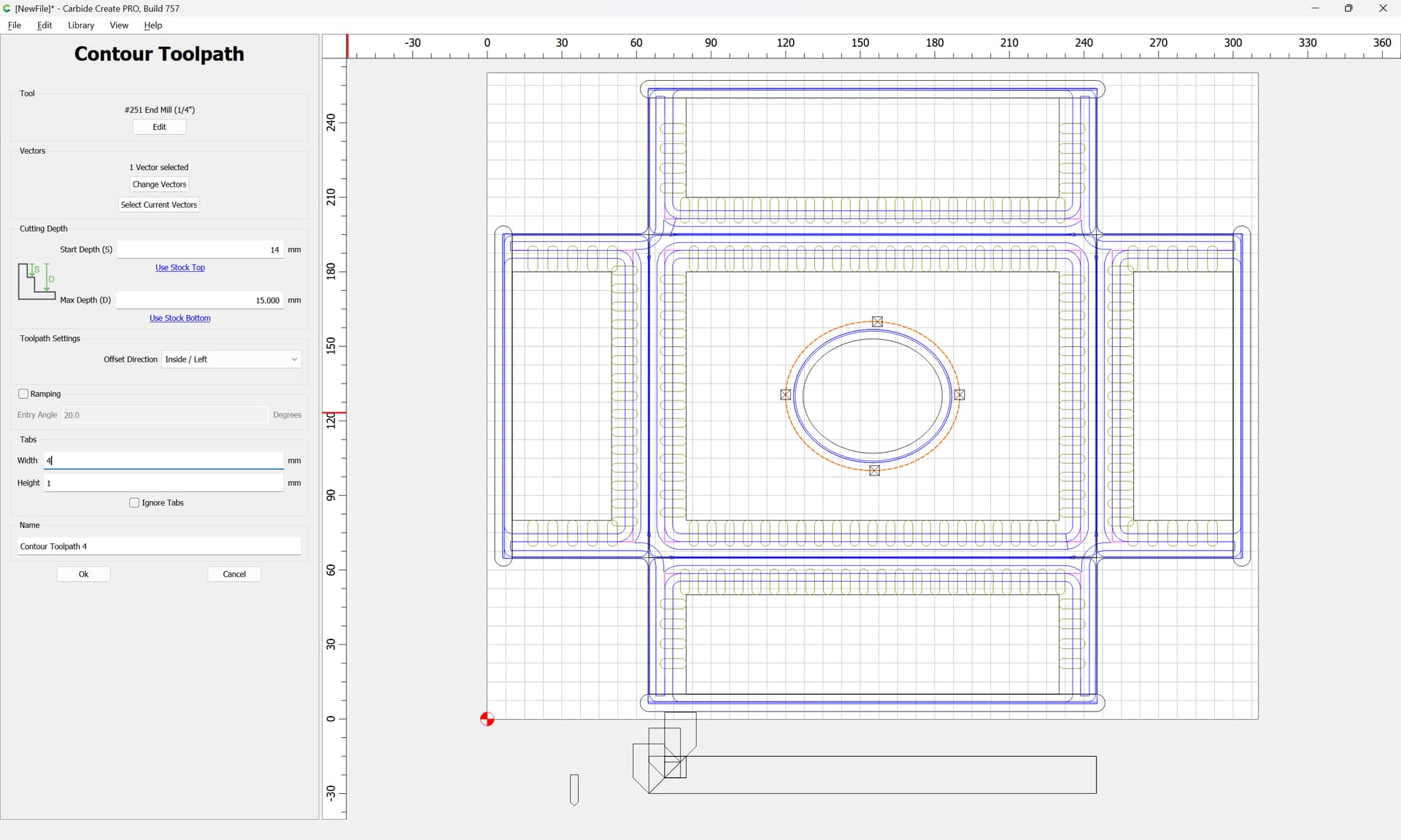
Then create an Inside Contour toolpath which starts at the bottom of the pocket and cuts the rest of the way through:
Move those toolpaths to the top of the group:
Because the joinery will be cut with a smaller tool, we can leave it mostly as-is:
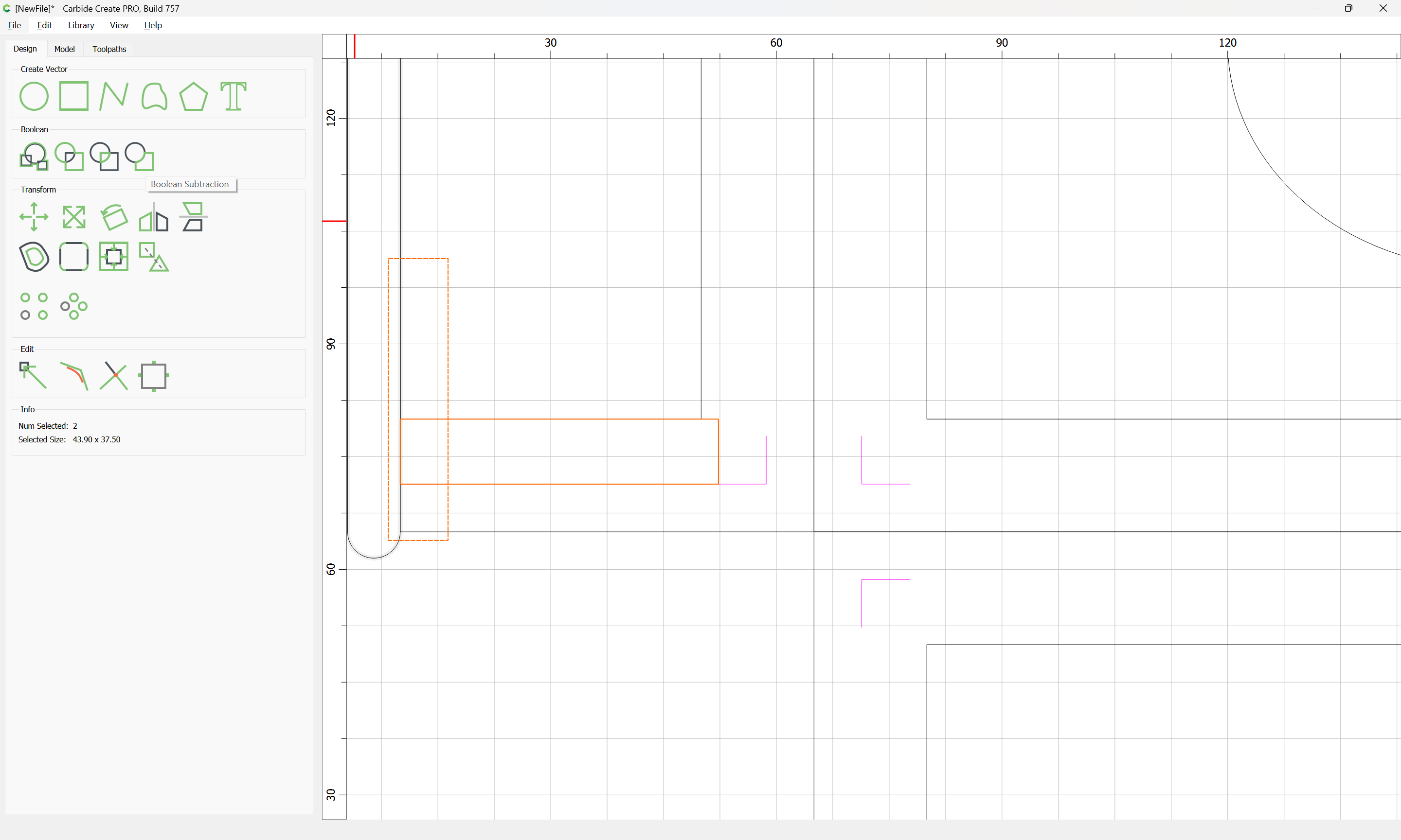
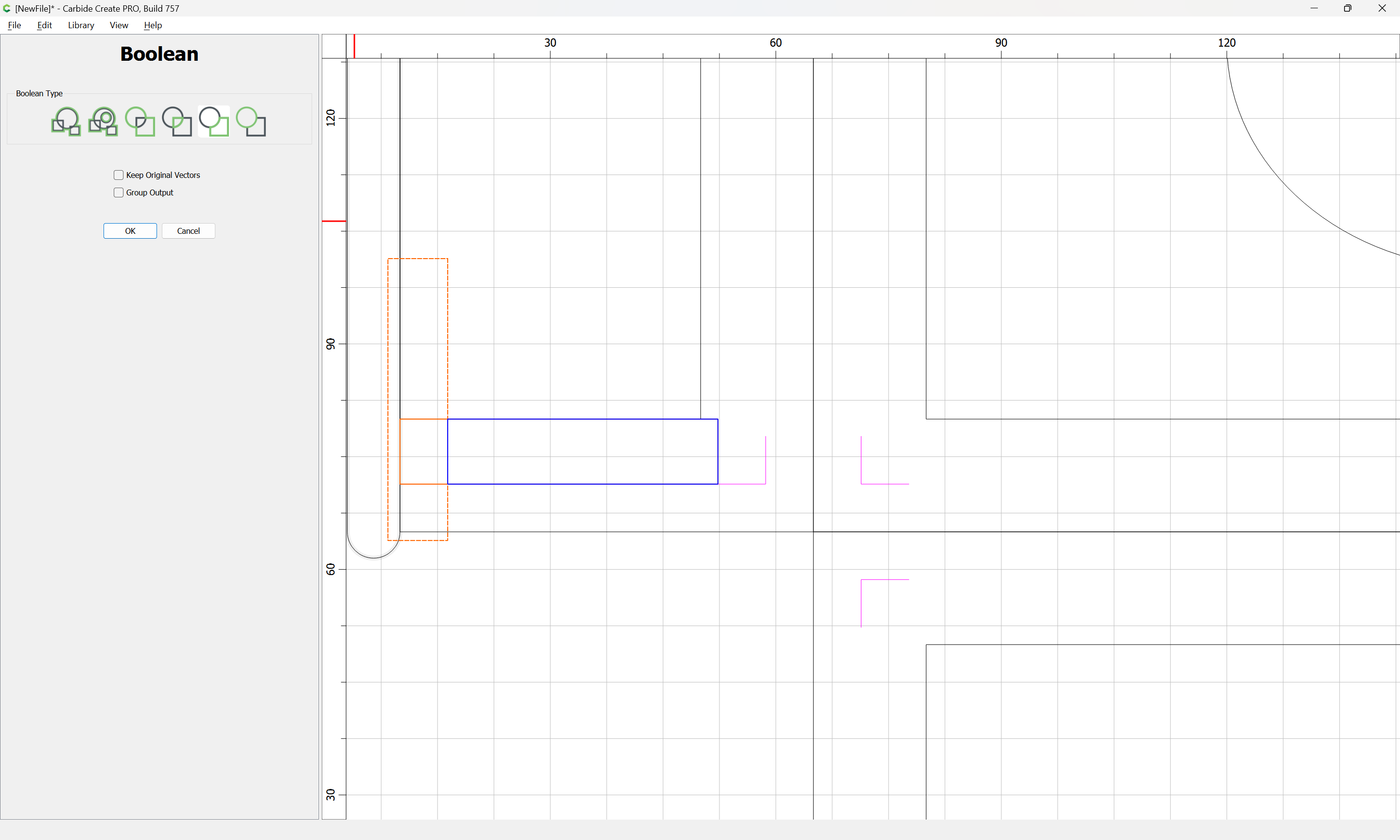
the only required adjustment is unioning the overlapping geometry — this can be done as a Boolean operation, or using Trim and Join Vectors, or one can simply flip some:
It is good practice to use a separate group for each tool, so:
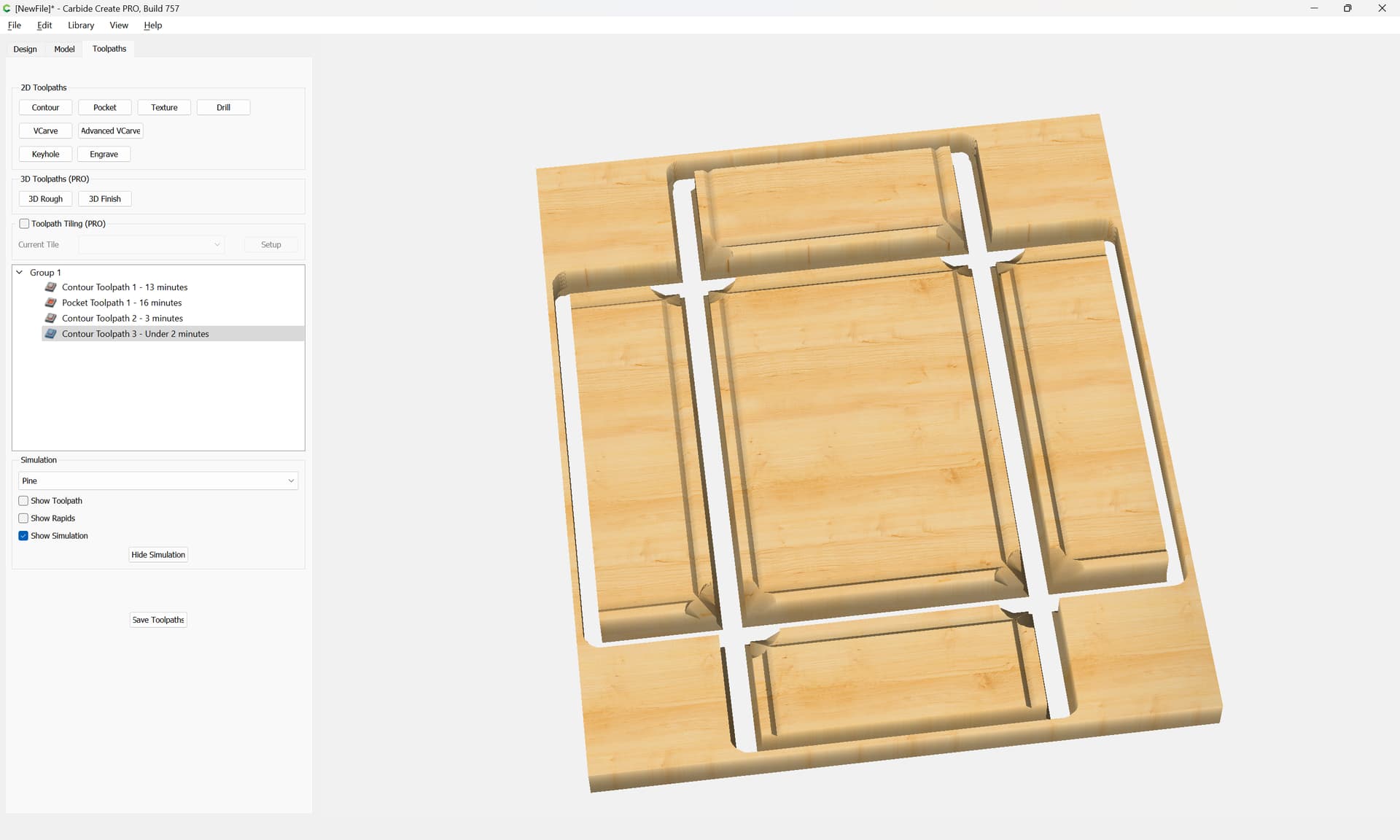
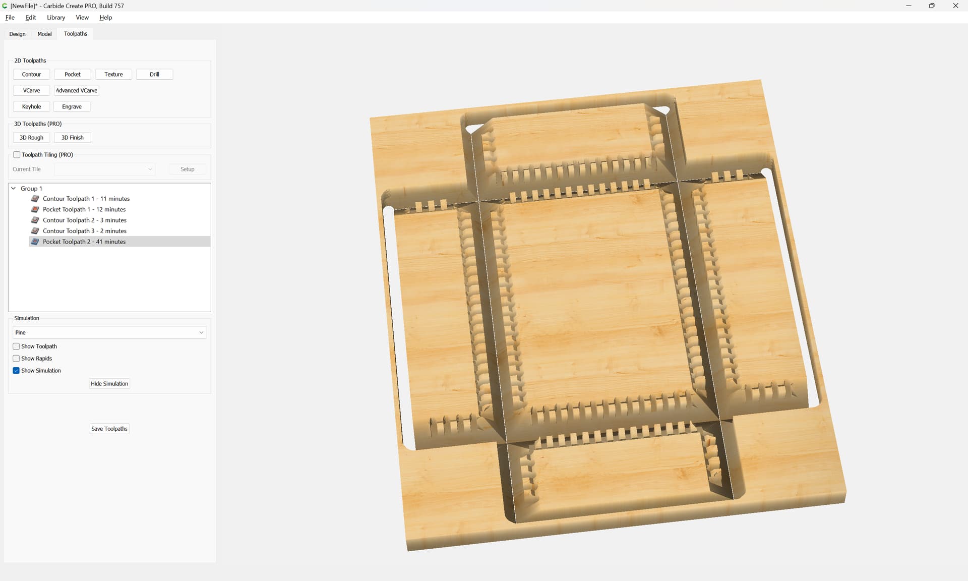
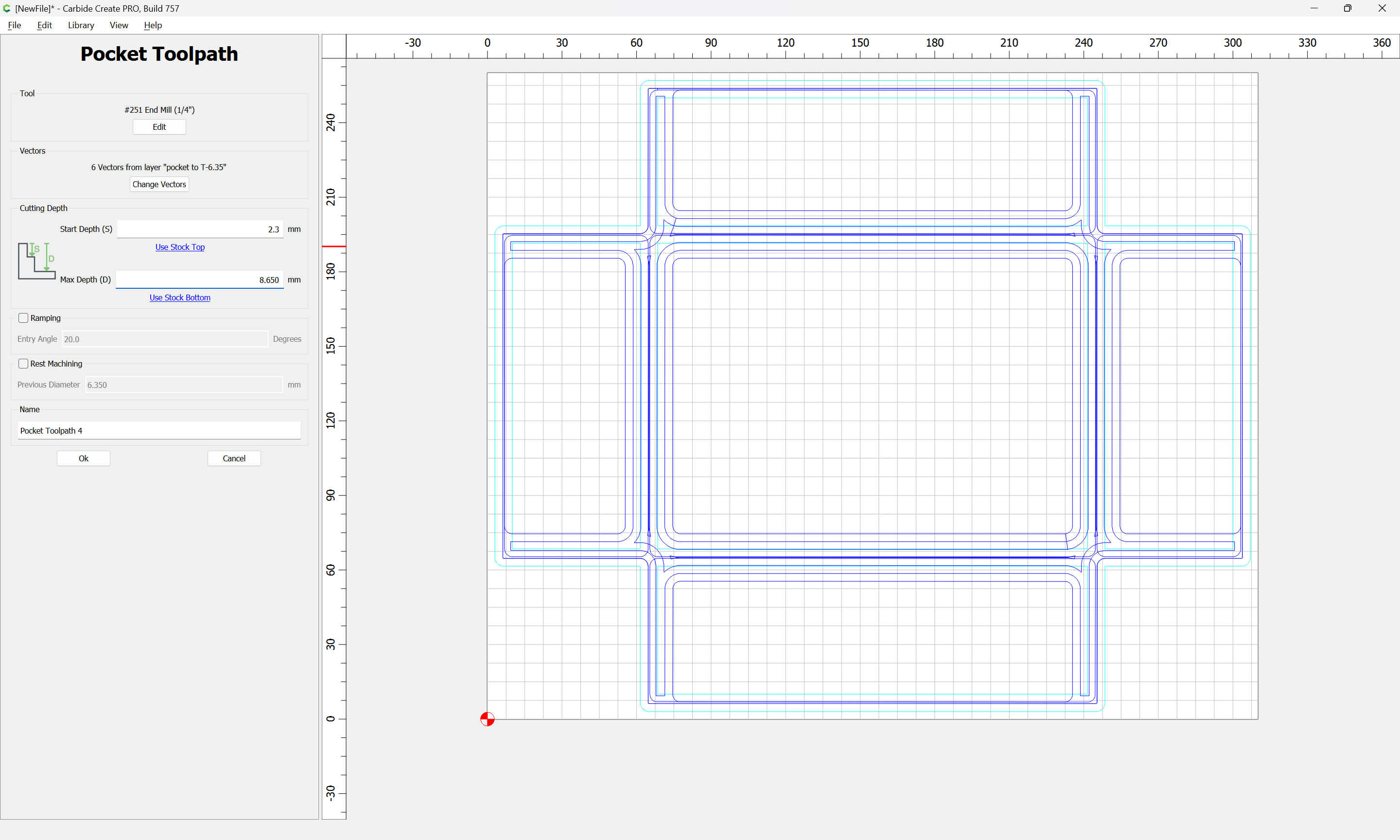
The last toolpaths are the V endmill cuts:
First the no-offset to 2.3mm depth:
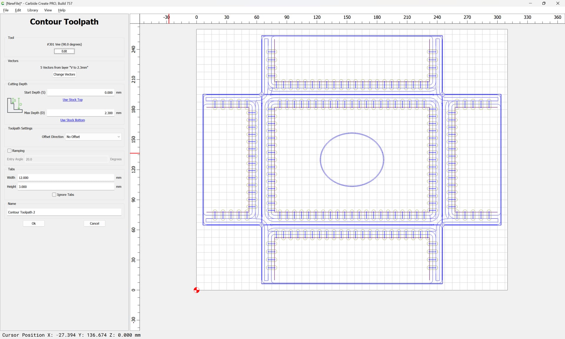
then the no-offset cut to the bottom of the pockets:
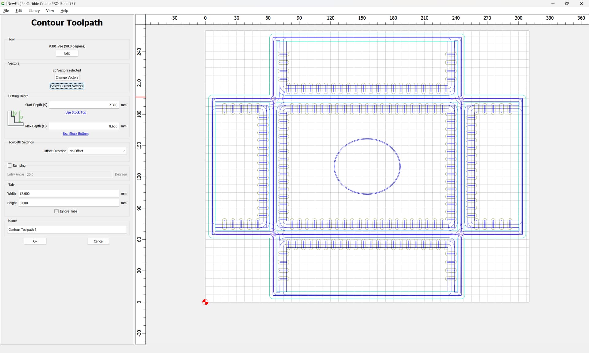
and last the V cut along the center channels:

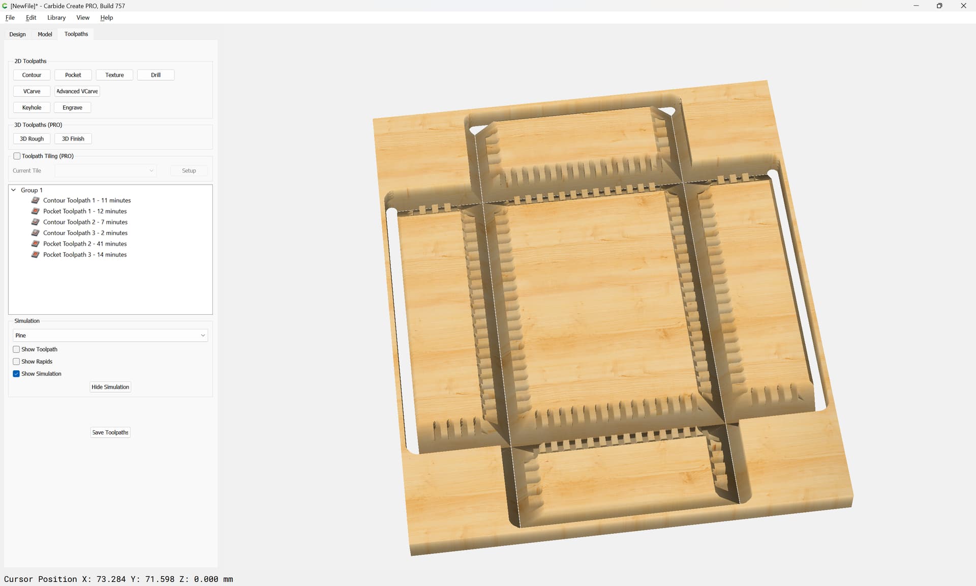
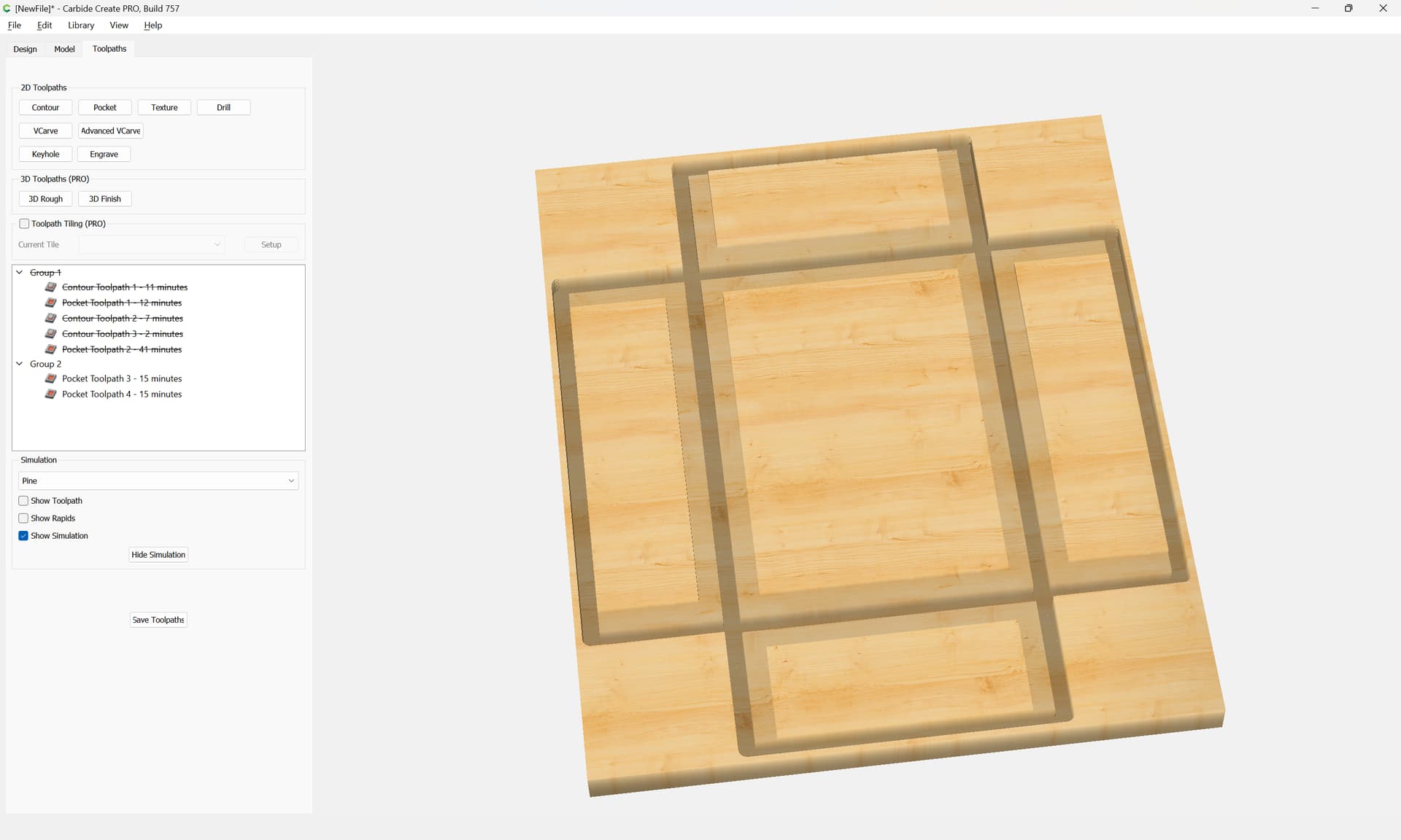
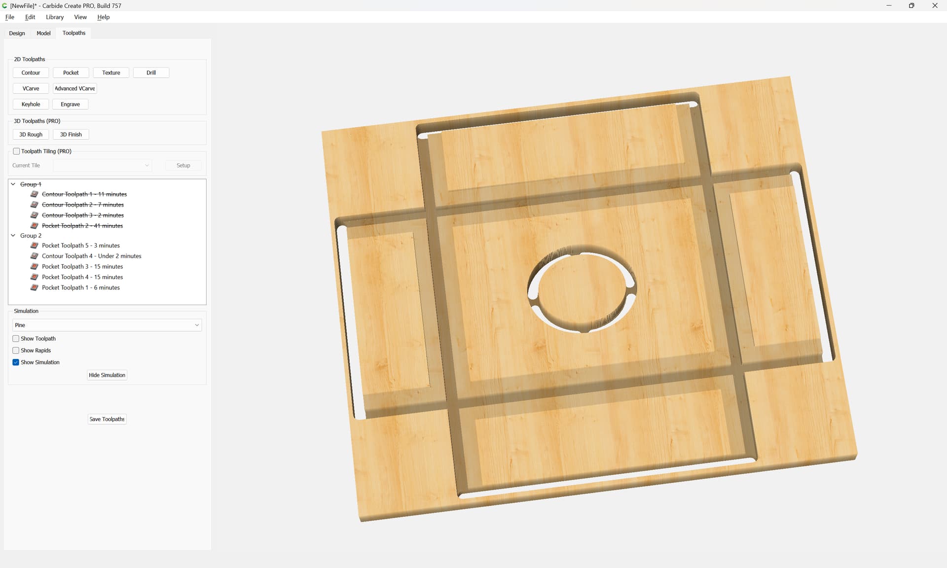
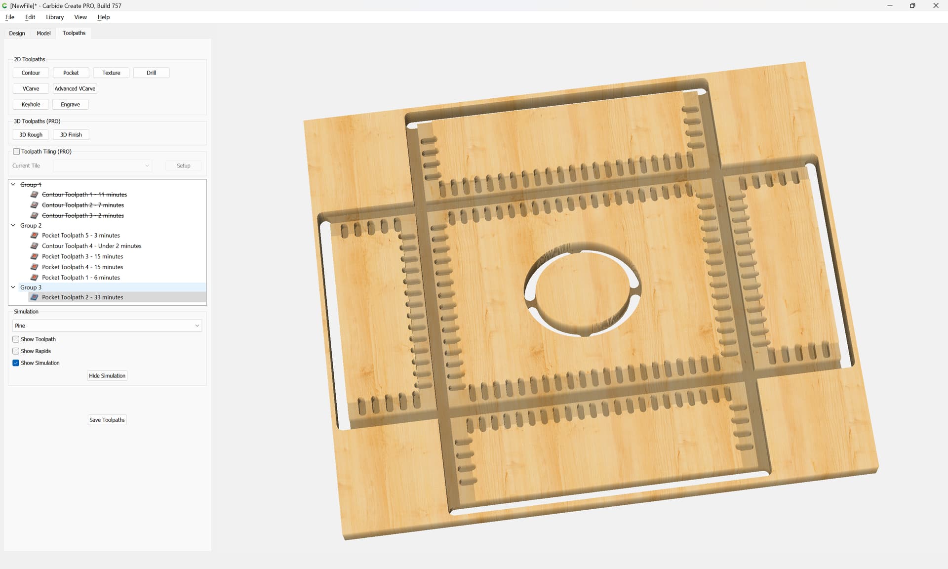
which all previews as:
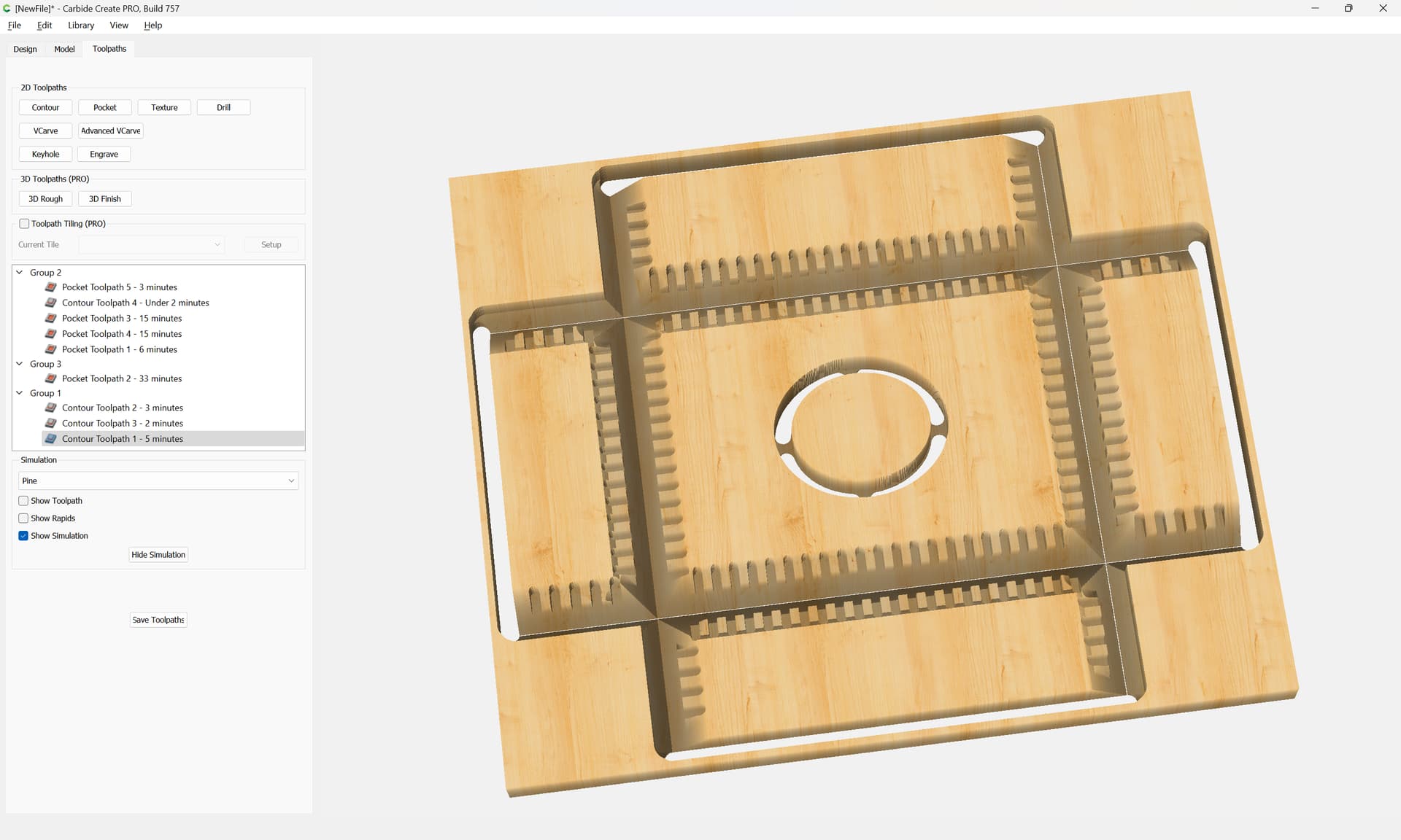
Attached as a v7 file.
tissue_box_v7.c2d (320 KB)
Please test the fit in a piece of scrap before committing expensive stock.
1 Like
I’ve followed along until about half way and then got stuck. I think this is too advanced for me. Without being able to spin the visualisation around it’s a bit confusing.
I wonder if I’m better off cutting the mortises with a regular bit and then tidying up the corners on the router table. The two stages are both very quick but there is a risk that the router bit widens the mortise slightly, of course.
The original idea was the vertical workholding but that comes with a lot of trial and error.
If I get to a big screen perhaps I will have another go with your method.
Ah you just uploaded a C2D so that might make things clearer