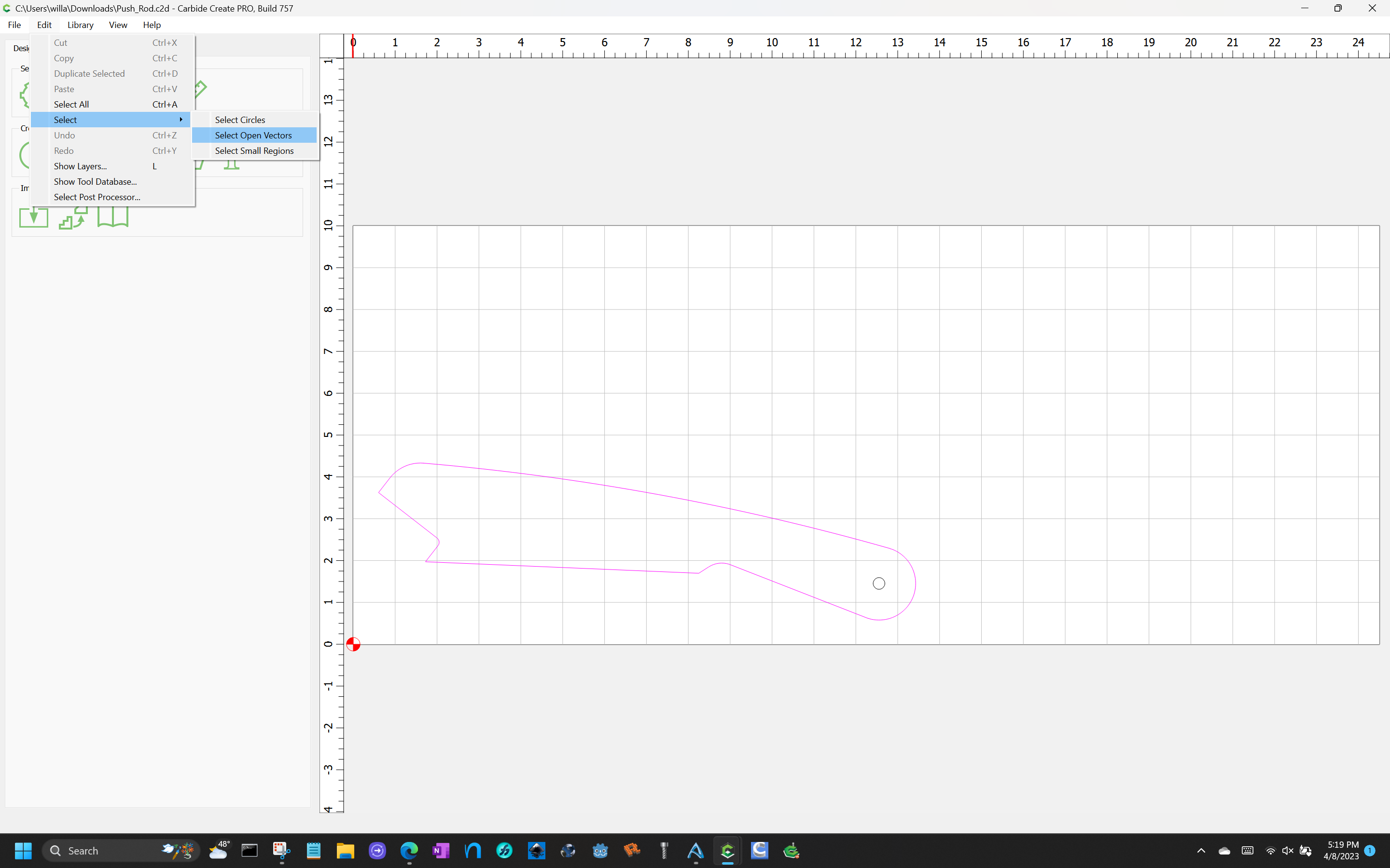
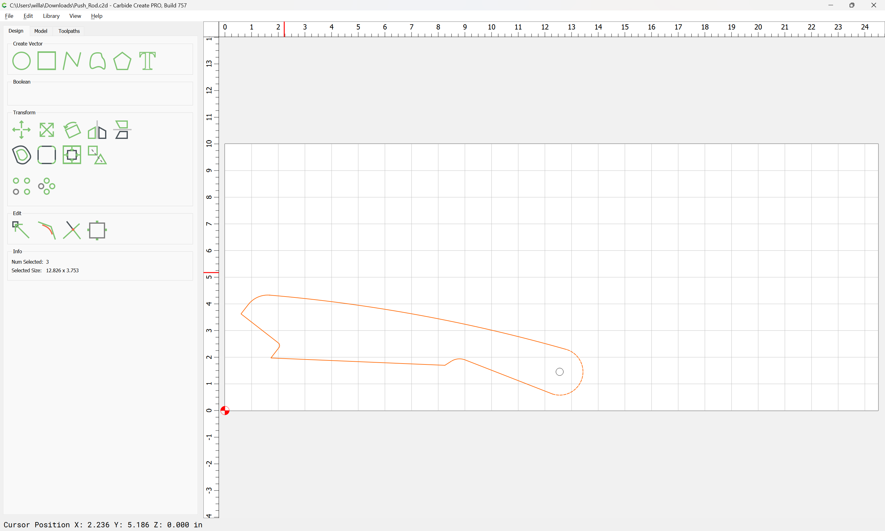
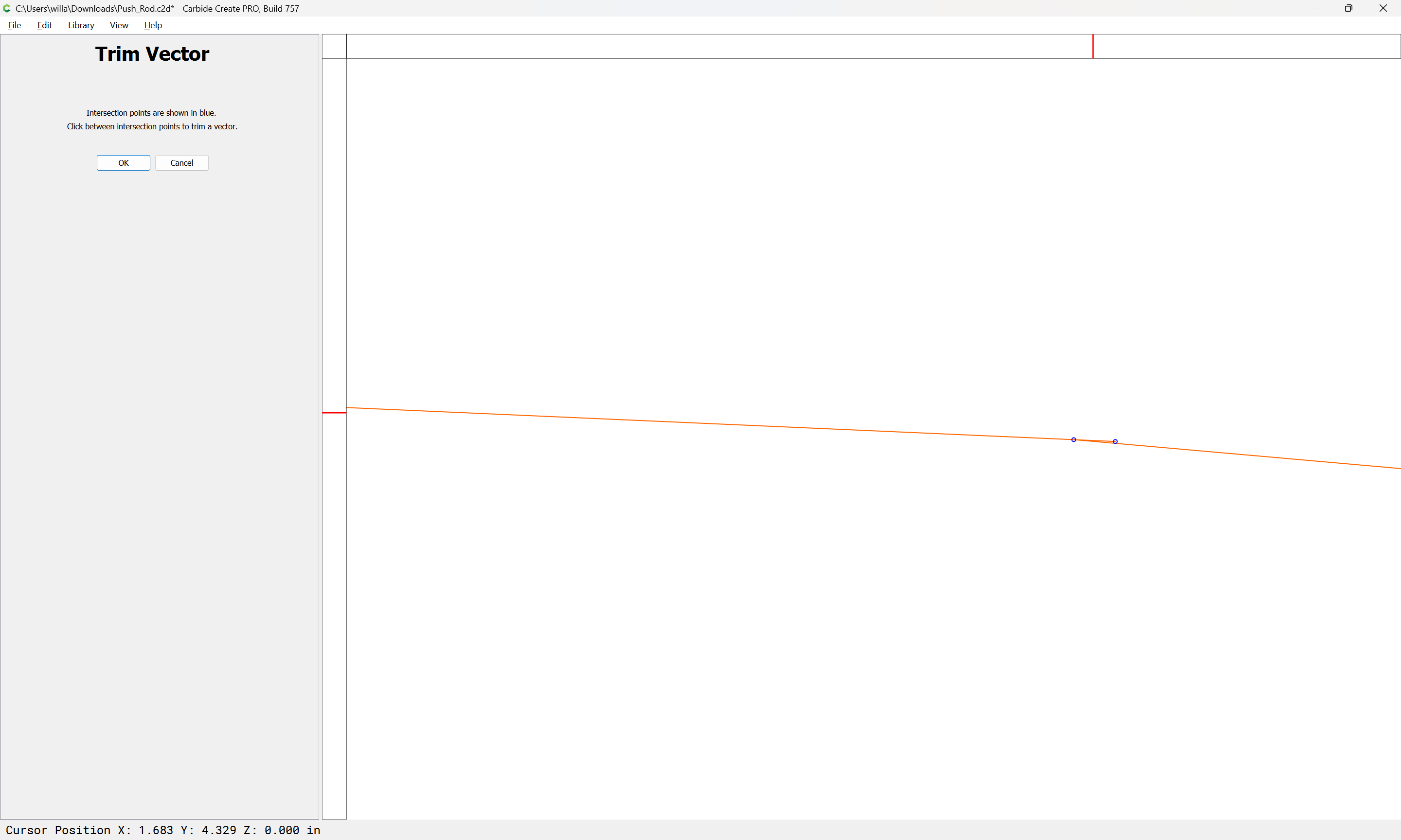
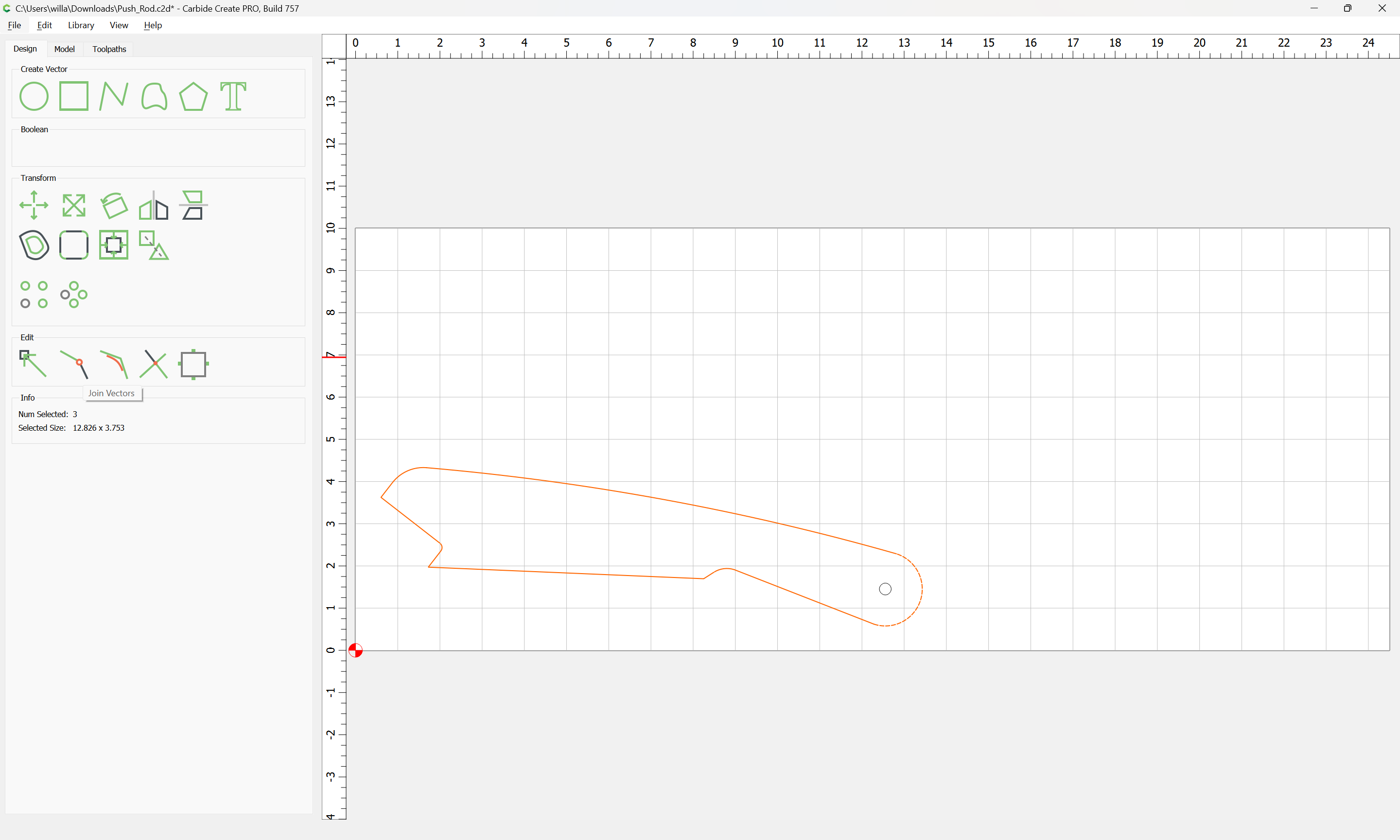
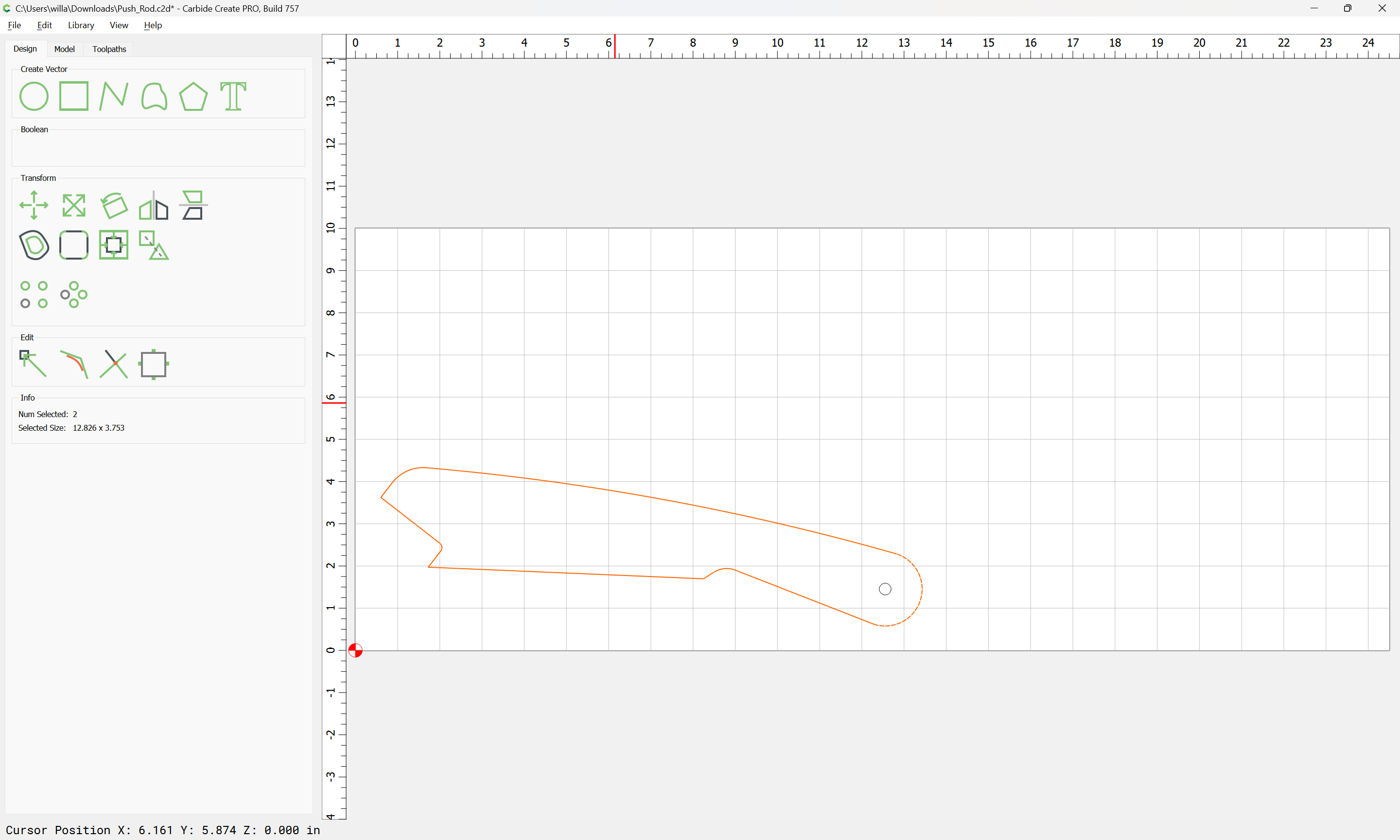
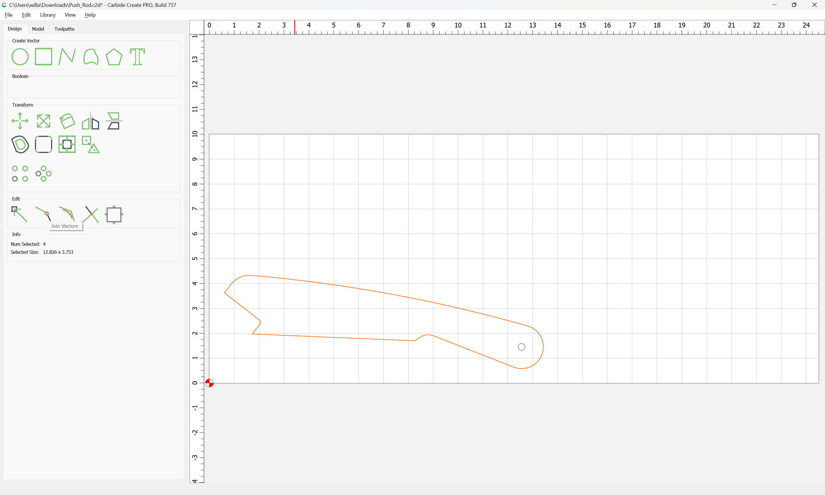
I have a push rod that I am cutting that was brought in as a DXF that is 1 piece with a hole in it. I have 2 tool paths, contour and drill. The contour is cutting in 5 different sections, meaning that there are 5 vectors. The design does not have these, so not sure how to combine everything to get cut path rather than 5. I went to design and used the combine vectors and somehow got it to 3, but again that is not right. I tried to group and ungroup without success (but I assumes that would not help anyway).
Also, when I initially brought it in an setup the offset direction to outside/right, the cutting path was outside of the design until it got the pushing section of the push rod, where it offset to the inside. Maybe they are related?
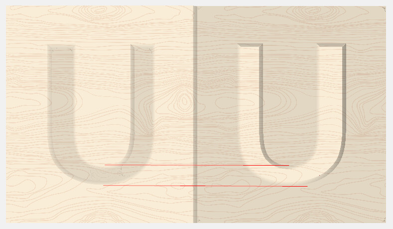
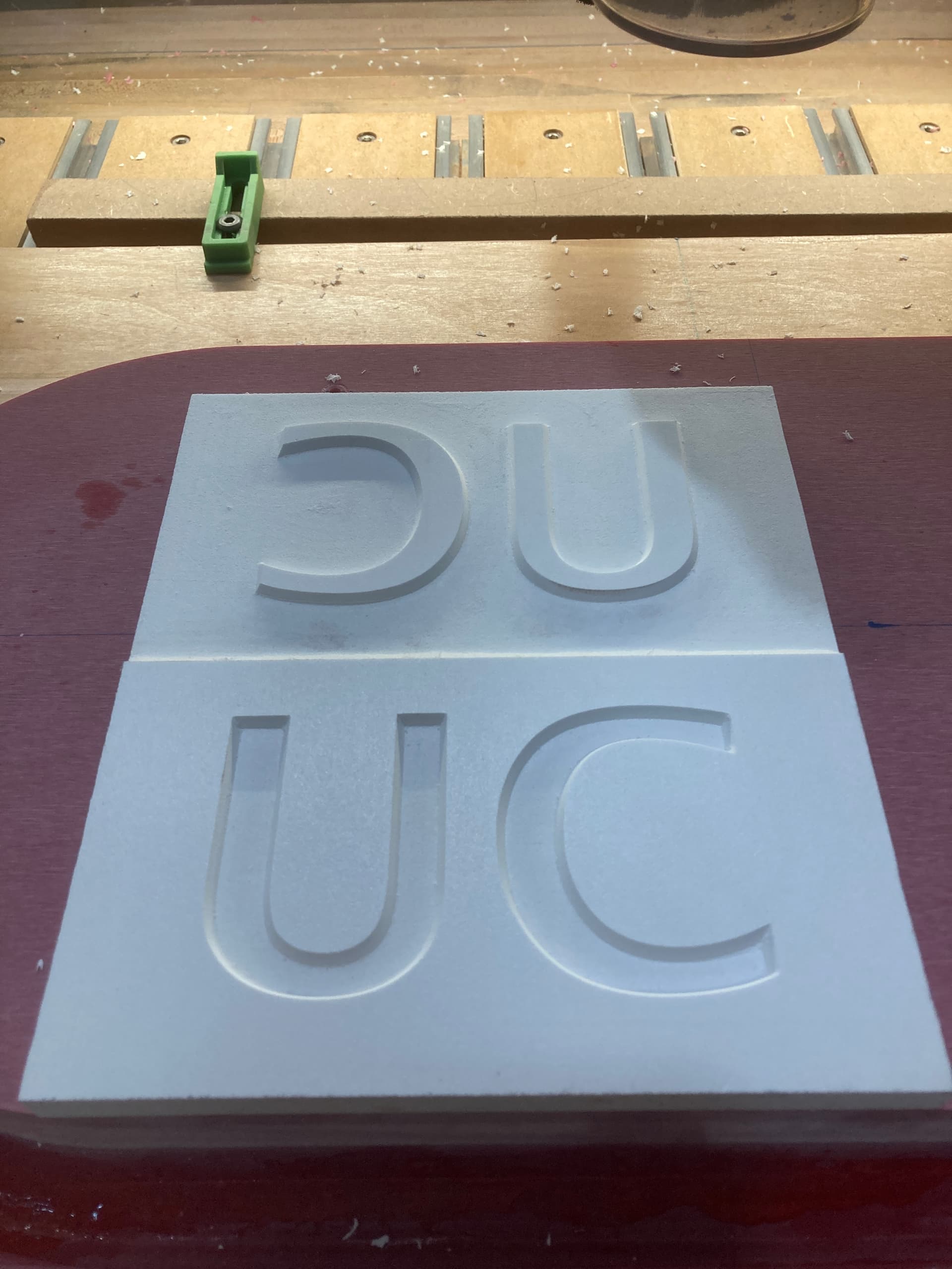
I am also having trouble with getting the programming and simulation to match. For instance I was cutting a ‘U and C’ and the simulation showed 4 passes to get to the 0.375" depth. I dropped it into motion, hit start and the bit drove to 0.375" and tried to cut everything out at once. That is attached also as ‘UC_Test’. It did it a couple time with the V bit as well when trying the Advanced V-Carve (depth of 0.250).
Will,
I did figure out the homing issue and again it was on me… Was going to ask about these 2 files. I built them and everything looks good, but they seem to be 1 to 1 and the male inlay will not fit properly. Maybe I didn’t hit something correctly during the design/settings. Sorry for the questions, just got the machine this weekend.
Is the 0.090 start not where the cut starts on the initial pass? The first time I did it, I set it up exactly like that exactly (after watching a video) and the end mill went down into the material way to far and started to cut, which I thought was because the start was at 0.09 instead of 0. My thinking was the cutter went into the wood 0.090 plus the amount it takes per pass and started cutting. Is that not what that means? By putting the start at 0.09 what does that mean in regards to the program? Maybe it is a definition I am overlooking / overthinking here?
Here is what happened with 0.09/.125. I sent program to carbide motion, zeroed the material on bottom left, started the program with the start at 0.09 and changed the bit to my end mill. Once I hit go on router and it went to start it plunged down into the wood a lot farther than the bot will handle and I aborted. I thought that is was the 0.09 as mentioned above?
Dave
Yes, Dave. Sorry about that. It does start at 0.090 plus the first cut depth.
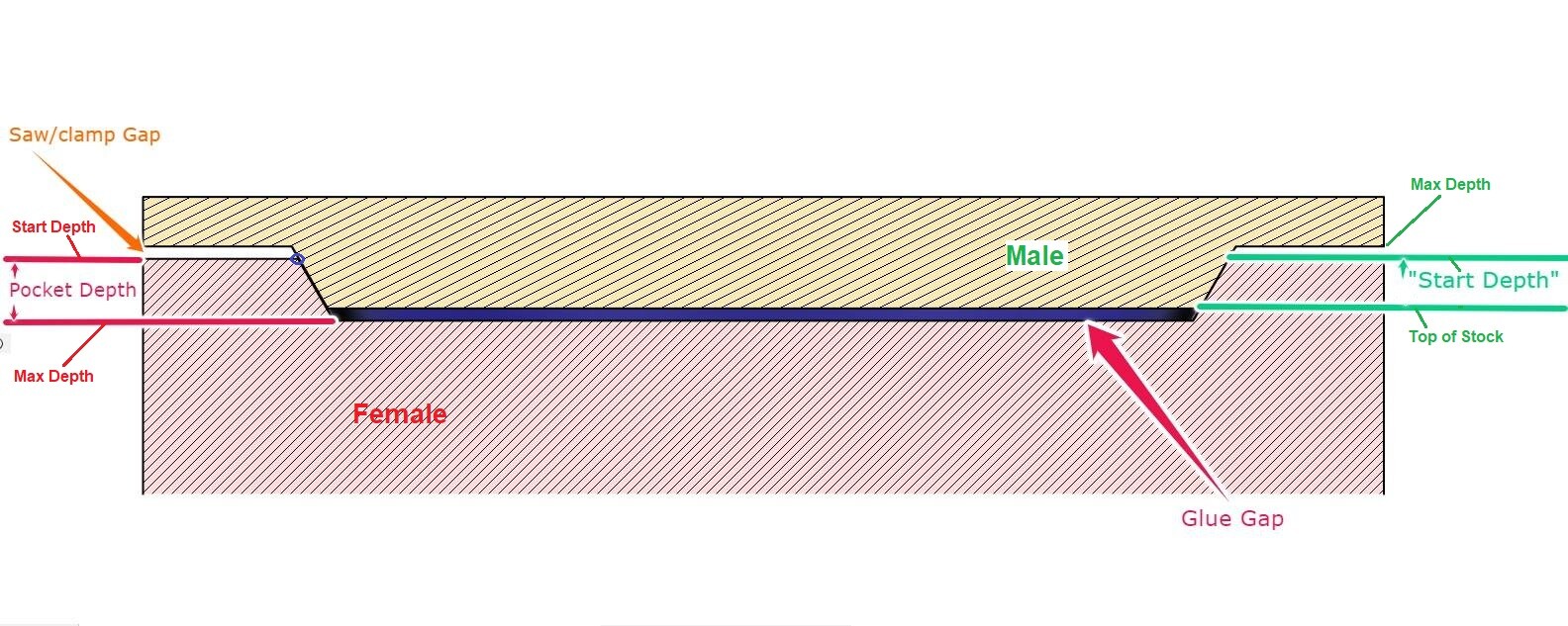
But it also profiles the vector you choose at that depth (so it fits the female side)
To clear it out do another Advanced V-carve from 0 to 0.090 with depth per cut set as desired.
The “Inlay” function in PRO allows you to set the “gap” depth for the profile line (vector) but still be able to step down to that depth.
Tod,
I do have the “inlay option” that has the bottom gap. What does that actually mean for the inlay itself. The gap between the male in the female once pressed together?
I was not sure what that actually referred to. I think that would be a good software update. To allow for hovering that describes the item your doing more.
Dave
Just tried again with these files and it just went down way too far and I had to stop the cut. Next I guess I will add a v-carve from the 0-.090 and forget about the inlay button. Not sure what is going on here.
The Bottom Gap sets the depth at where the vector gets traced. Because the vector is at the top of the female feature, on the male feature it has to be at the bottom so it will fit into the female.
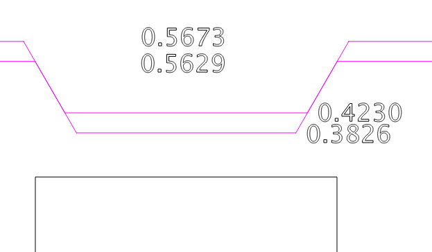
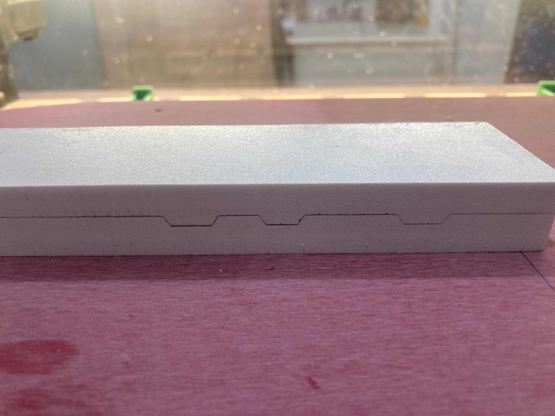
In my picture above, the little blue circle is the vector. Previously the Start Depth determined where the vector was traced. But that also forced the first cut on the male to be the Start depth plus the depth of cut. Usually just cutting the whole thing to full depth in one pass.
Now with the “Bottom Gap” setting, you can leave the Start Depth at the top so you get multiple levels, but still tell it to trace the vector at “Bottom Gap” above the bottom.
If you can walk us through the steps, maybe we can see what’s going wrong.
Detailed… Something like
Start Machine & connect CM
Initialize machine. It moves to back right top, then front center & prompts for a tool. It measures the tool
Machine was initialized (went to back corner, moved to front, asked for bit, set bit and moved back to front).
Set the zero on the bottom left corner of the material
Saved and loaded the new program with the 0.090 start and the 0.125 max depth
Once loaded, I acknowledged the program and clicked start
Moved to ‘add bit’ location, added end mill and it went to bit setter.
Went to location to ‘turn on the spindle’ location and I adjusted to hardwood speed and turned spindle on.
Hit ‘go’ and the machine went to the top right and drilled a hole about 3/8" - 1/2" down which is way more than it should have
Stopped and reinitialized
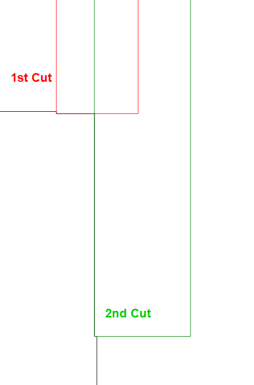
Later I changed to 2 passes on advanced (one being 0-0.090" and the other being 0.090" - 0.0125"). Same process as above. When I started that program the spindle went to the top right side of the mirrored ‘C’ and started. This worked, but I had to sand the male down a bit because the bottom of the male was touching the bottom of the female and I could feel a little slop side to side. The odd thing is I ran this 2 stage program next to the big hole from above (because it was going to be in the cut out area) and after the program was completed that is when I noticed just how far the end mill went on the program above. WAY more than 0.125" and more into the 0.375". Very odd.
OK, after setting zero at the lower left corner, try checking the stock height at several places, center & the other corners. Then if that all looks good, manually change the tool by selecting “Change Tool” in the run menu, then go back & check your Z on top of the stock again.
If that is good. Manually machine a flat along the top of the part along the front edge. Just mdi S12000M3 (or whatever speed you want), then jog the tool to make one pass to get a good flat height.
Whatever height you end up at, set that to Z 0
Then jog in front of the piece, down an even known dimension. Say 0.500" if you have room, or more if you can. Move the cutter so it’s taking a skim cut 0.010 - 0.020", just enough that you can measure the depth of the cut. This will tell you if your Z axis is calibrated correctly
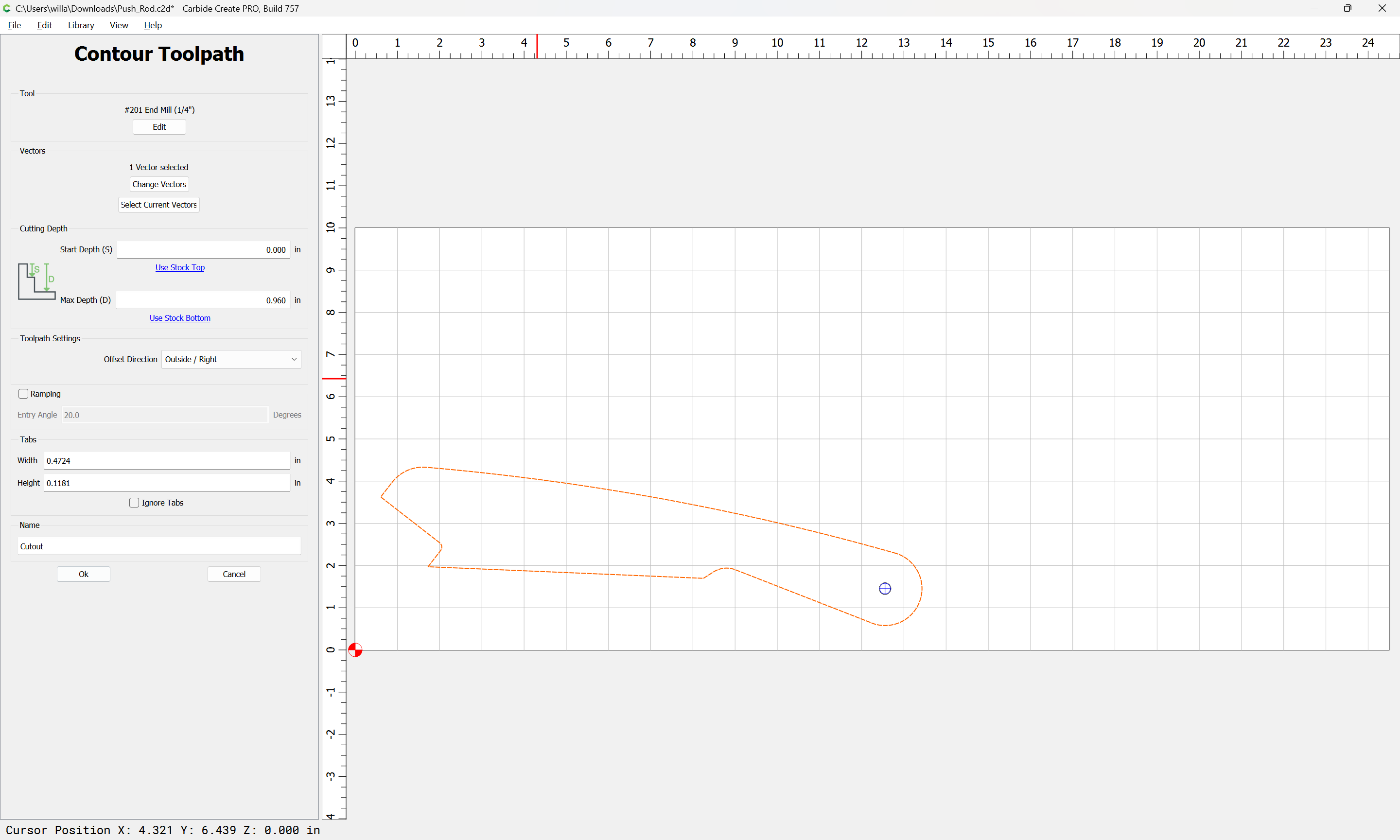
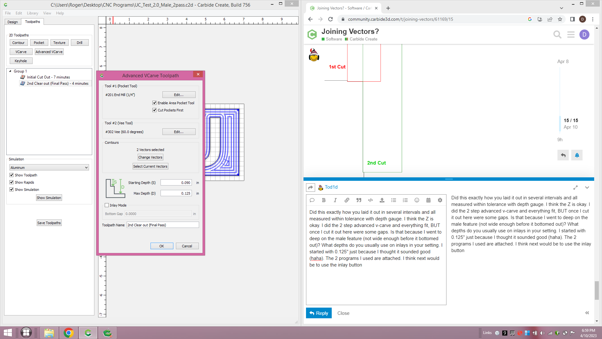
Did this exactly how you laid it out in several intervals/steps and all measured within tolerance with a depth gauge. I think the Z is okay. I did the 2 step advanced v-carve and everything fit, BUT once I cut it out here were some gaps. Is that because I went to deep on the male feature as I did have to sand it a bit (not wide enough before it bottomed out)? What depths do you usually use on inlays in your settings. I started with 0.125", on the female, just because I thought it sounded good (haha). The 2 programs I used are attached. I think next would be to use the inlay mode as shown in the picture but dang is it a little confusing still and I don’t want to break bits… I appreciate the help with this, BTW!
Alright, tried it out. They are tighter than I expected, but did fit nicely.
I think I might increase the gap to 0.050, So, for the male Start: 0.075 Max: 0.125
Awesome. Those would be the settings using ‘Inlay mode’ correct? Also, curious did you cut them at the same time? Is that possible with different thicknesses of material? I assume you have to build that within the tool paths and start with the thicker one and move down to the thinner one (and change the start depth? Just a random thought… Appreciate the help.
With inlay mode you’d still use 0.0 & 0.125 for both, and set the Gap to 0.050
I just imported your “Male” .c2d file into the Female file & moved the male up to cut all at once.
You could do that with different thicknesses of material but you’d have to shim the thinner piece to match the thicker piece to they’re the same height. (Or set your start & max depths based on the height of the thicker piece.