Thanks Tod! I will give this a try again.
Not sure why this keeps happening. I keep getting unconnected vectors coming from AutoCAD to Carbide Create. I draw the items, save as DXF and then insert them into Carbide Create. Every time I have done that, I have to fix the drawing again because of the nodes not touching. This is not the case in the CAD file.
The community has the following notes:
- it may help to use the OVERKILL command to eliminate any overlapping or intersecting paths before exporting from AUTOCAD
- if lines have different elevations, use FLATTEN
- PLINES are intrinsically joined, and should be used where appropriate
- AutoCAD 2000 DXF format (model geometry only, base model scaling) export from the desired face (not isometric view)
- 2004 Lines
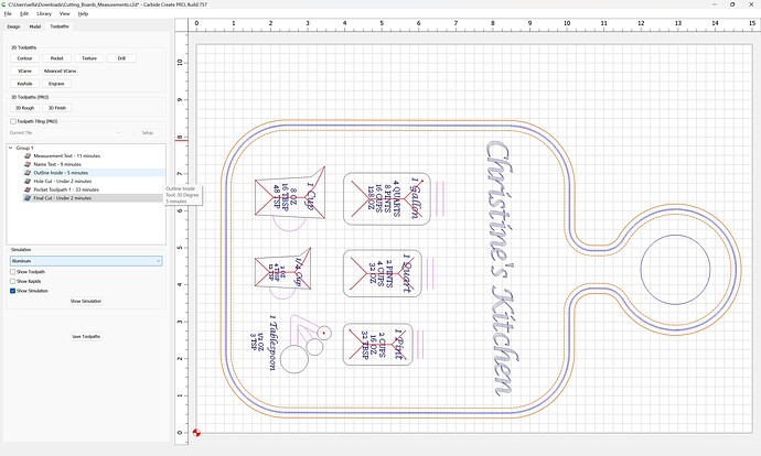
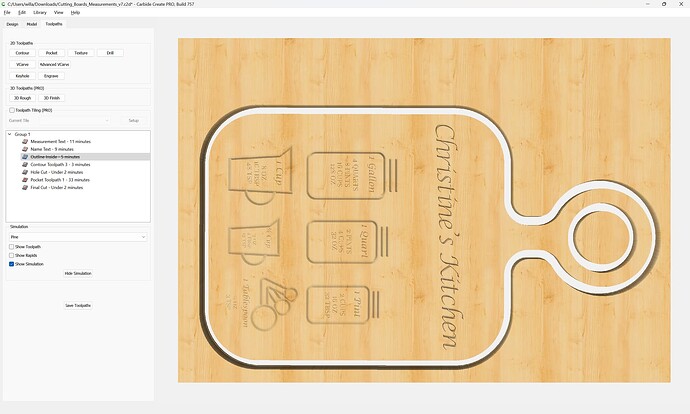
Would you all be bale to tell me what I am doing wrong on this program? Do I need to convert something on the text and the outlines?
Cutting_Boards_Measurements.c2d (1.1 MB)
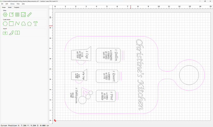
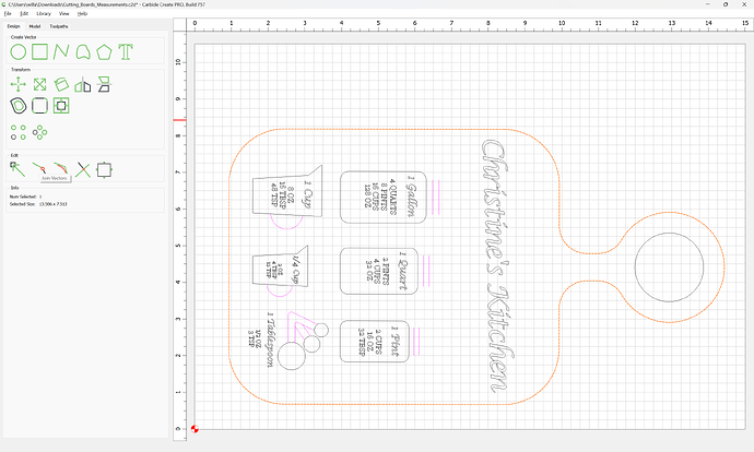
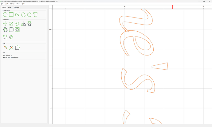
First off, you have open geometry:
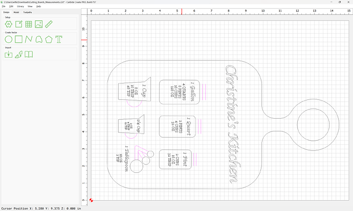
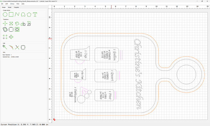
Best to close the geometry for the outline:
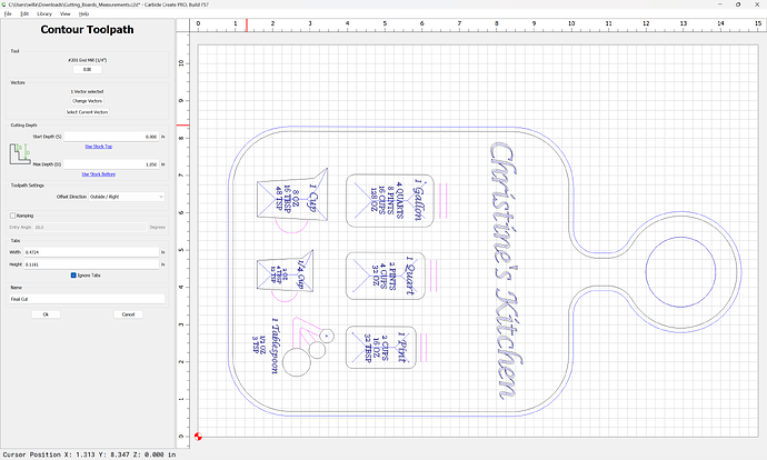
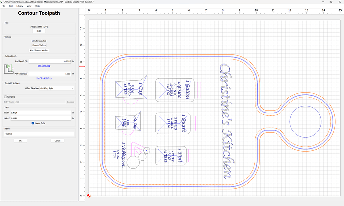
and you are cutting this outline as an outside contour toolpath, which is a slot as narrow as the endmill:
which is over 1" deep — do you have a tool which has 1" of cutting flute length?
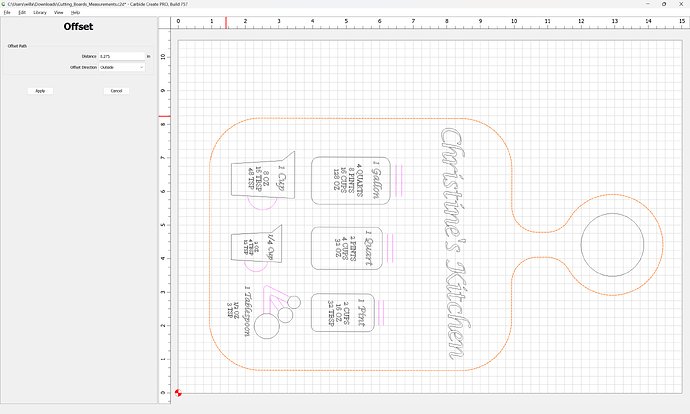
Add offset geometry which is endmill diameter plus 10% or so:
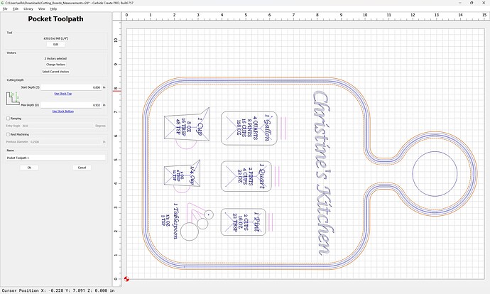
and cut as a pocket down to tab height or the penultimate pass:
change the contour so that it begins cutting at the bottom of the pocket:
and move it to after the pocket:
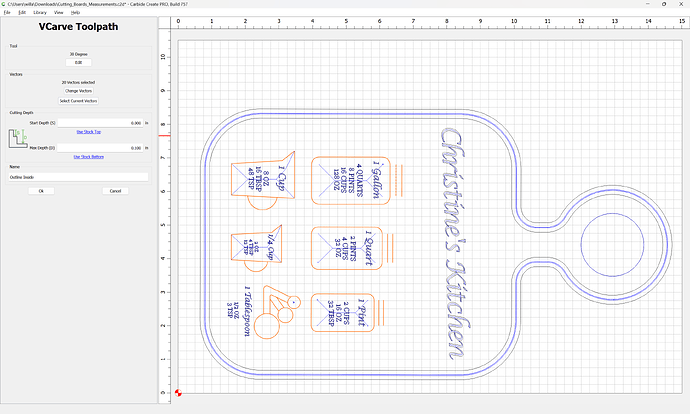
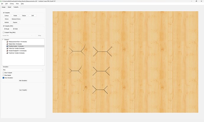
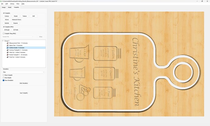
You are using a V carving for “Outline Inside”
which is not yielding the desired result:
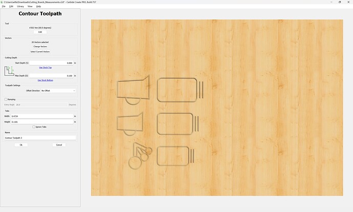
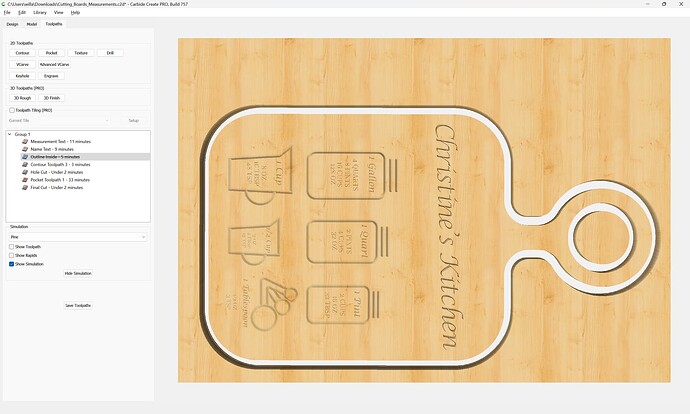
Instead, use a No offset contour:
which I believe is more along the lines of what you want:
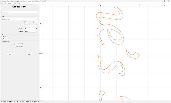
One further adjustment, rather than a stick/unidirectional computer quote:
use a proper apostrophe for a possessive:
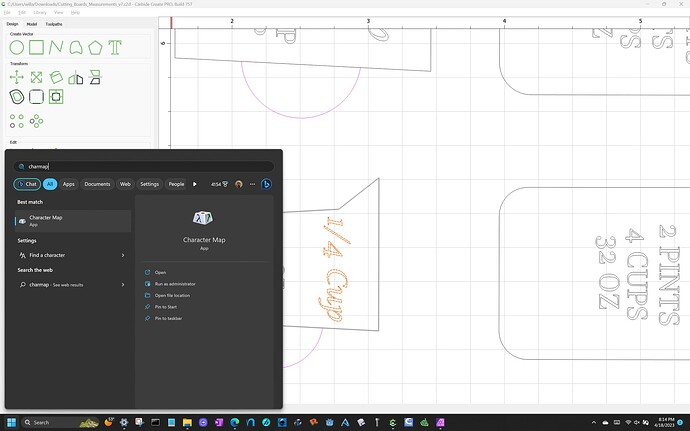
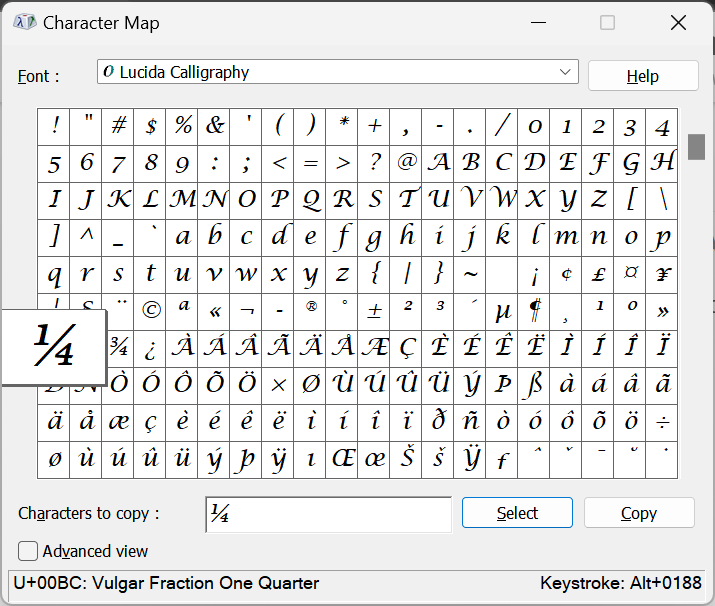
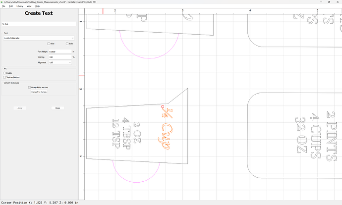
Similarly, rather than a shilling fraction 1/4, use the proper symbol — you can get it using charmap (or the Mac equivalent):
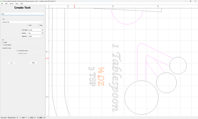
Same for 1/2:
and you may want to use tabs to hold the part in place.
Attached as a v7 file:
Cutting_Boards_Measurements_v7.c2d (1.0 MB)
Wow Will, thanks. Did you do the pocket cut because of the flute height / wood thickness? The piece I am actually cutting is less than 1" (I changed it out and never changed thickness on here because it would not work for me anyway). Would a simple contour would work if I did that?
Sorry it seems as though these are just stupid misses on my end…My apologies.
Any time you are cutting more than the half the endmill diameter deep you should consider reducing tooling engagement by adding offset geometry and cutting as a pocket.
I’d caution against cutting deep then the length of the cutting flutes — might be you can get away w/ it in wood, but it seems risky to me.
Understood. Yeah I have done some breaking bits on my old kit.
Today I learned!
“Shilling Fraction”
"In typography, a fraction typeset by simply using standard numerals, separated by a shilling mark (or slash, /). Also called fake fractions or adaptable fractions.
Another question. Is there an exact process for beginning a cut? Today for instance, I did the following in order.
- Downloaded Project
- Zeroed it out with the dowel in the bit zero
- Started the project
- It then traversed to me and I changed the bit to my 30 degree.
- It then measured via bit setter
- Turned on the router and it went to start cutting and plowed straight through everything and broke the tip off my 30 degree.
Then I tried it this way and no issue:
- Re-downloaded the project
- Zeroed out the 30 degree bit on the piece of wood the old way (piece of paper)
- Started program and traversed
- No need to change bit and then it measure
- Running fine as we speak
I know that I have use the bit setter and the bit zero and they have worked 100% on other cuts. Is it something with the order of operations because now I have a broken 30 degree. Do I need to download, zero with a dowel, start program, switch bits, and then start (exactly)?
Will, this was using v7 from above.
Where did you set the origin in the file?
Did that match where the origin was set relative to the stock?
For the BitZero see:
and see:
They are both in the bottom left (forward, front). I checked the Z position in reference to the bit zero like you mentioned in the thread before and it was working fine. It has done this a couple times, but not sure if it is my approach and setup that is doing it. Its like it loses it which make me think that I should be doing the zeroing out at another point in my process. Also, checked the Z like Tod mentioned above too and nothing seemed to be off about the measurements. I have something going now that will also verify the Z (with the zero being done with the paper method).
Please let us know step-by-step:
- what you did
- what you expected
- what actually happened
at support@carbide3d.com and we will work through this with you.
Hey Tod,
Wanted to circle back to this as I just got to do it. I did another test and ran into the same problem with the male being too skinny. Is there something in this you see that was wrong? I used the recommended setting from above.
UnCommon_Logo_Inlay_Male.c2d (84 KB)
UnCommon_Logo_Inlay_Female.c2d (88 KB)
On the female side you shouldn’t be using the “Bottom Gap”. Otherwise it looks good.
Dang it… I debated that… So by putting that gap on both it basically offset, didn’t it? Learning is hard.
Yes. The term “Bottom Gap” might be misleading. I think what it means is “How far up from the max depth to you want to trace the vector to cut the male inlay?”
Before the inlay feature, you would specify this with the “Starting Depth” on the male inlay.
The problem there was that it assumed you were already cut to that depth & didn’t honor the “Depth of Cut” on the tool, and just cut full depth, or “depth of cut” below the starting depth.
Now with the new inlay option, it defines where the vector will be traced, but still allow to make multiple cuts to get there.
It seems with the tests & projects I’ve done the Glue Gap & Saw Gap end up being a bit smaller than what I programmed. A little bit of runout on the cutter, and/or just the properties of the material allowing it to be pushed in a bit further than designed could contribute to this.
I’ve resolved to making the gaps a bit bigger than what I’m shooting for to allow for this.
This topic was automatically closed after 30 days. New replies are no longer allowed.
