You can export an STL from OpenSCAD which should then be machinable in MeshCAM or some other 3D CAM program.
Another option would be to add some geometry and then export a DXF which would be ready to import into Carbide Create for machining.
You can export an STL from OpenSCAD which should then be machinable in MeshCAM or some other 3D CAM program.
Another option would be to add some geometry and then export a DXF which would be ready to import into Carbide Create for machining.
OK, I opened in OpenSCAD but I must say that i’m at a loss about how to proceed or even modify the one you created.
I just came back from plowing snow, I will have to look at creating a fixture, I don’t have materials to replicate yours at the moment.
There are a couple of other fixture designs, at least one is also on Cutrocket.
If you’ll let me know dimensions (board thickness and width) I’ll gladly work out how to get a DXF to put into Carbide Create and then cut.
Alternately, if you want to cut using flat parts we can work up a relieved fingerjoint design if that would be workable.
Just testing so it is not for a given project but I may use that in the future. I will try my VCarve first as I’m familiar with the tool. I have some idea for a simple fixture with materials on hand, I will try to see if it works.
3D carving these geometries will be … interesting
steep inclines, small holes, etc
These should be trivial — it’s all right angles and curves — just clamp two boards on the machine, cut, then repeat for the other three corners — it was the first machined joint, it was designed to be easy to machine.
A little more code and we have a file which can be wired up to make the shapes one would need to cut out, so should be suitable for exporting a DXF:
Next up is cleaning up the code, documenting it, doing a version for Thingiverse, and then seeing about a cutting file using TPL or METAPOST.
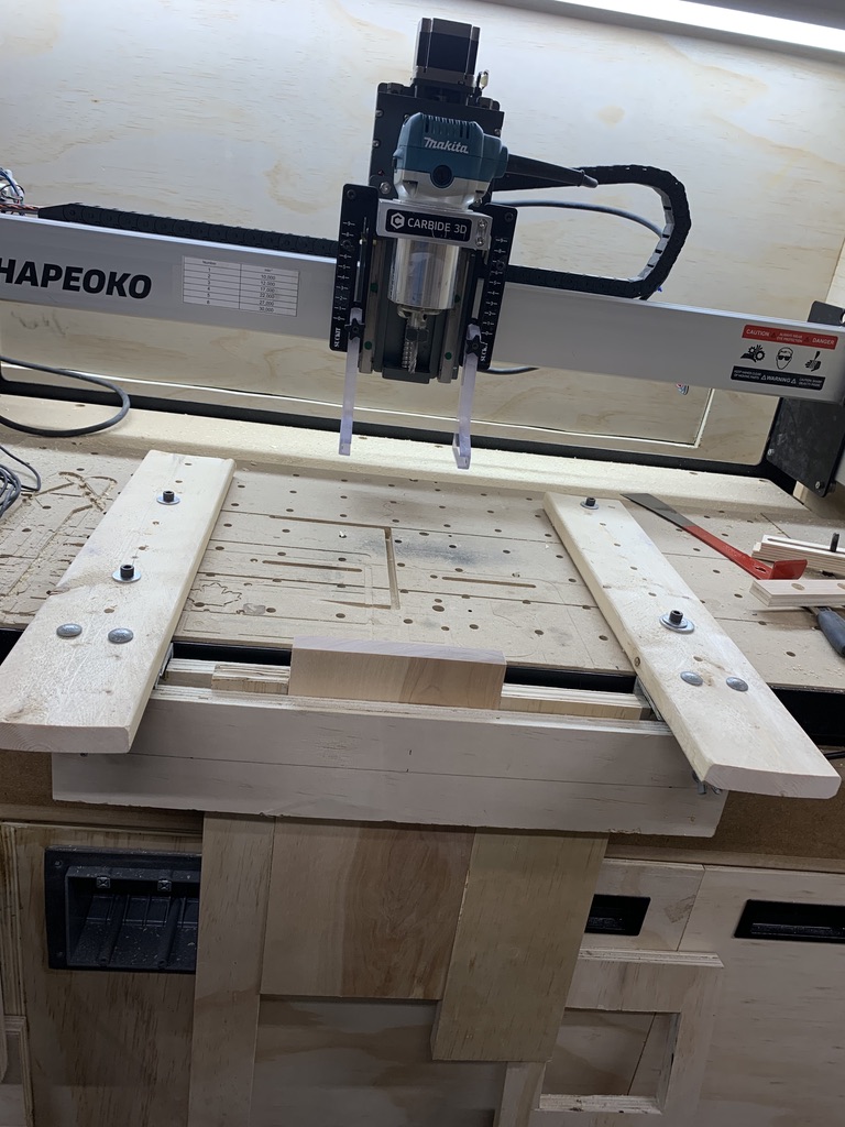
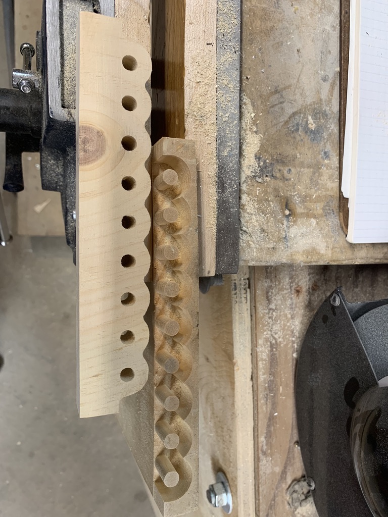
Ok this morning I ran the first tests of the Knapp joint on the Shapeoko using VCarve Pro and my new vertical jig.
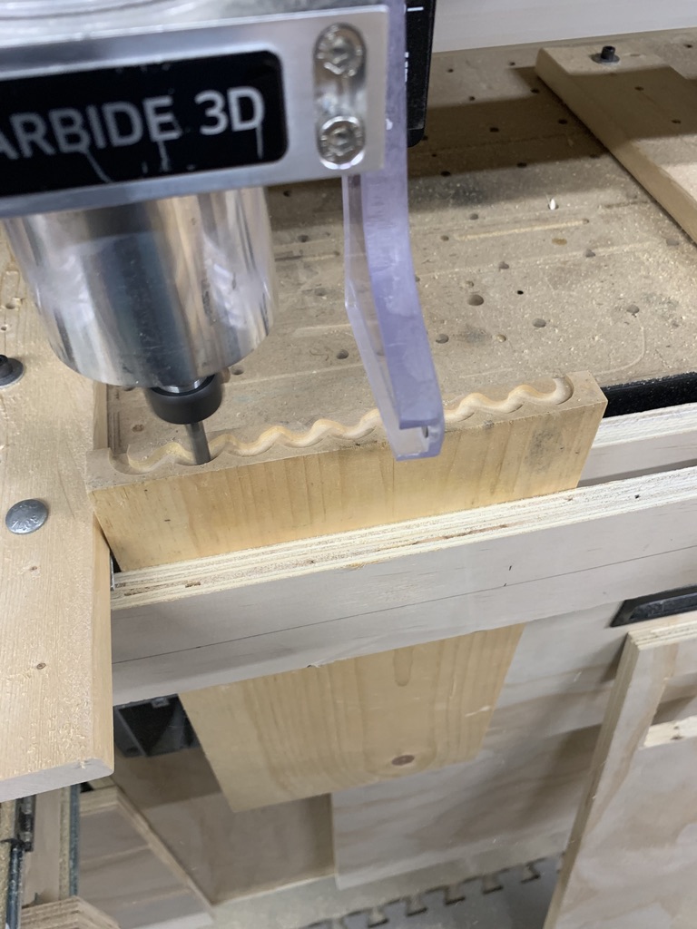
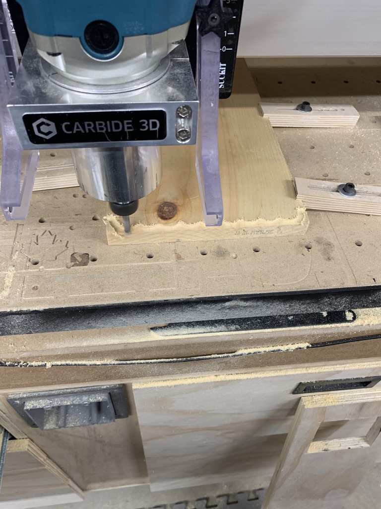
I tested using a .250 endmill in a scrap piece of pine. The test ran fine but unfortunately, as @WillAdams had mentioned, there is a small discrepancy between the male and female parts due to geometry. I had expected that and was planning to use a 1/8" endmill for the tight areas on the scalloped portion of the female joint. I remembered that the pantorouter uses a dowel of the same size as the bit to follow the template and this is probably why there is no discrepancy on the joints produced by the pantorouter.
I did however have a discrepancy between the size of the dowels and the holes but I’m not sure why. I cut one on the inside and one on the outside of the line but I may have to use an allowance offset to make the dowels slightly smaller. I will run a few more tests to see what would make it work.
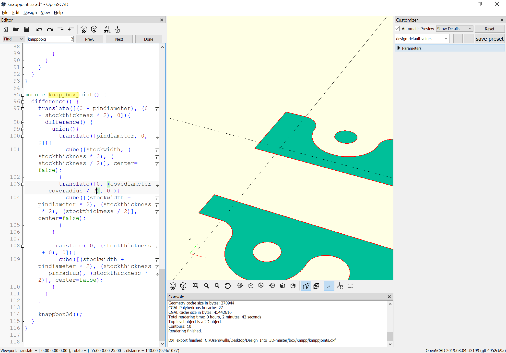
And we add support for the Customizer, project things to flat:
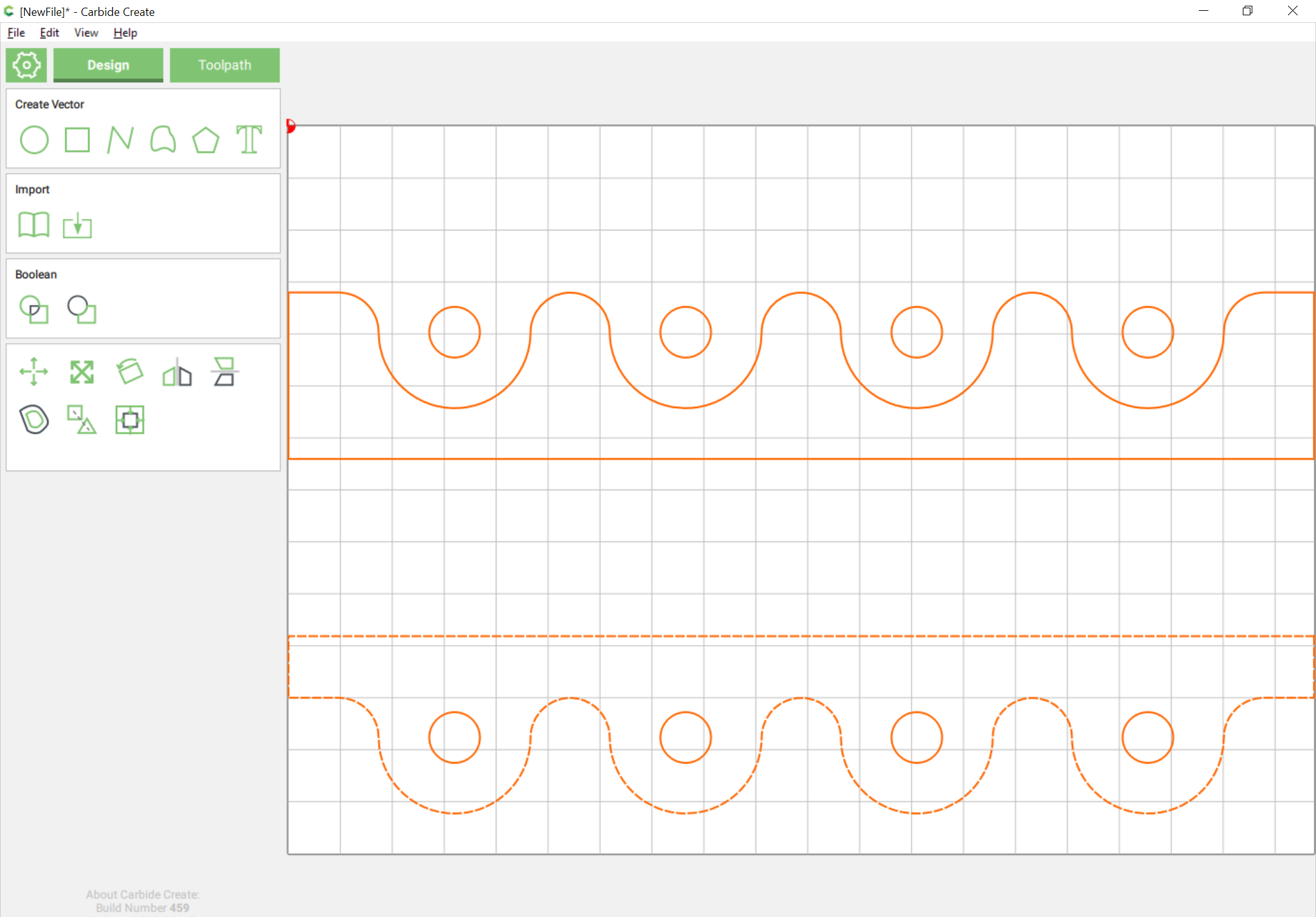
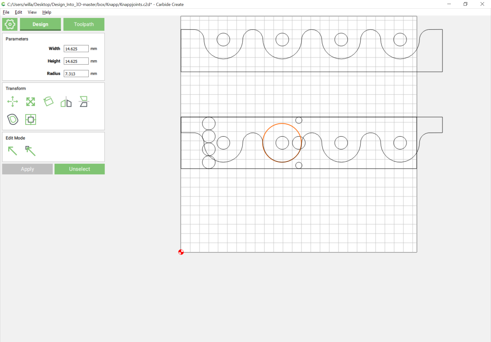
and we get a DXF:
knappjoints.dxf (150.8 KB)
which imports, (after fixing the variable/calculation which was wrong):
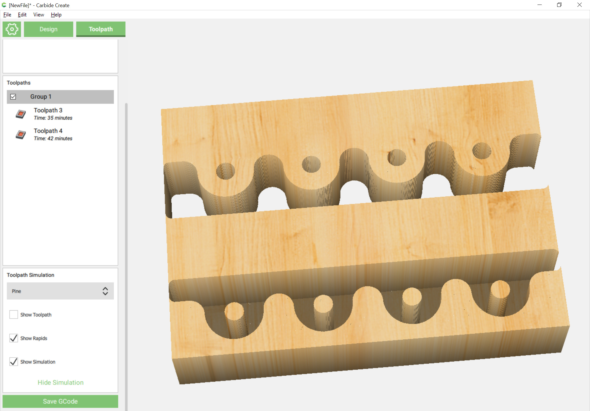
which when assigned suitable toolpaths previews fine:
Even though it isn’t quite, so we import things into our drawing file:
which makes it obvious what the calculations should be
It occurs to me that you could make this joint with both boards flat on the table, if only those annoying pins weren’t there. The joint would be plenty strong, what with all that glue surface. But I know people like a mechanical aspect to a joint for drawers, so what if you didn’t cut the pins, but kept the holes, glued the joint, and then just took a drill bit and deepened the holes, so you could pound in a dowel. Does that make sense?
Using this method, and assuming the drawer parts were small enough to fit on your machine, you could cut all the ends of your drawer in a single job. Might be a very fast and simple way to get a bunch of drawers made.
You can’t make the joint flat on the table and make it void free as you can with a rabbet — the scallops would have a rounded bottom.
I’ve been looking at this, and actually tried working through one design I had for a blind miter hidden spline joint, but ran into limitations of current CAD/CAM tools. @fenrus worked up a nifty tool which should help on that, but I’m not good with it since I can’t work up a nice previewer environment which suits me.
I’ve had yet another idea, which unfortunately has an obvious name collision but not sure how long it will take to work through that.
Yes you are right, I had thought the same thing you would have a scalloped male and female with matching holes that could be milled flat on the board and you insert a dowel of the matching size. I would call this a modified Knapp joint. I guess I should try it too.
I wanted to try the traditional method but the other certainly would meet the aesthetics of the joint and probably the strength while having a simplified construction.
Yeah you are right, you could do the modified Knapp but you would still need to do this with the male piece in vertical position. The holes instead of the pins would probably speed-up the process somewhat. Inserting the dowels at assembly would require a bit more time than hammering the joint into the pins. I’m still foggy this AM, I need another cup of coffee!
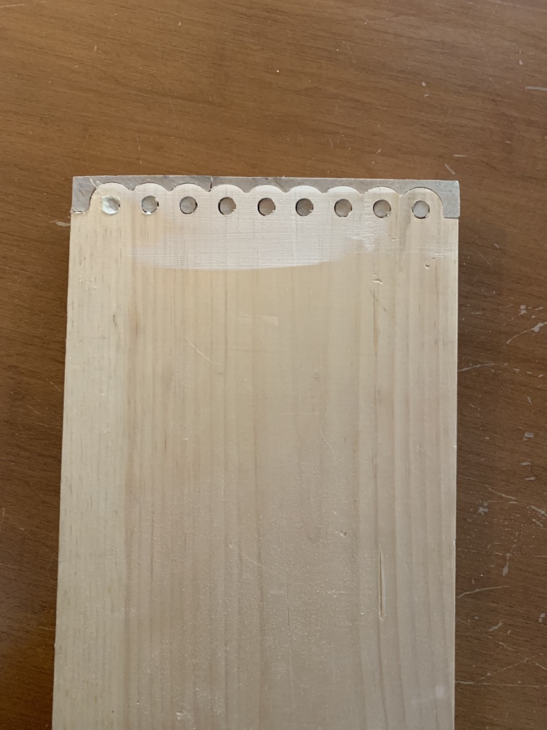
Success! While it is not perfect and needs a bit of fine-tuning, I was able to produce a Knapp joint using VCarve Pro.
I had to add an allowance to the holes in the female portion so the pegs were not as tight but I did not have to modify the scallops when I used a 1/8 in endmill for the female portion. Please take note that I used some scrap wood to do the test and it reflects a bit on the quality.
To fix the issues, I have to decrease the allowance just a bit and I would increase the depth of cut for the male portion so the pegs fit flush or even stick out a bit.
Note that there is some interesting discussion of other designs for this sort of thing at:
c.f., https://makezine.com/2014/12/04/50-digital-wood-joints-poster/ and https://furniturefab2013.files.wordpress.com/2013/09/joints.pdf
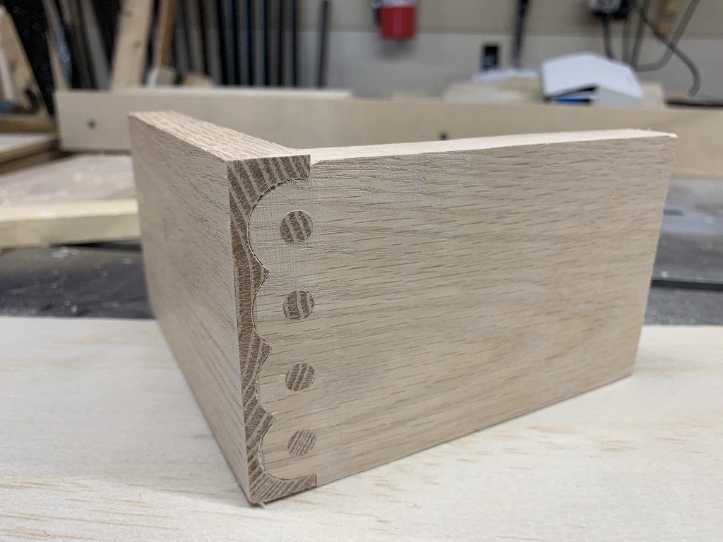
OK success! Today I was able to complete my test of the Knapp Joint using VCarve to create the toolpaths. The joints is almost perfect, I did not use any glue but after dry fitting the two parts together, It appears that it would be very difficult to take it apart.
My quick and easy vertical holding fixture also works very well.
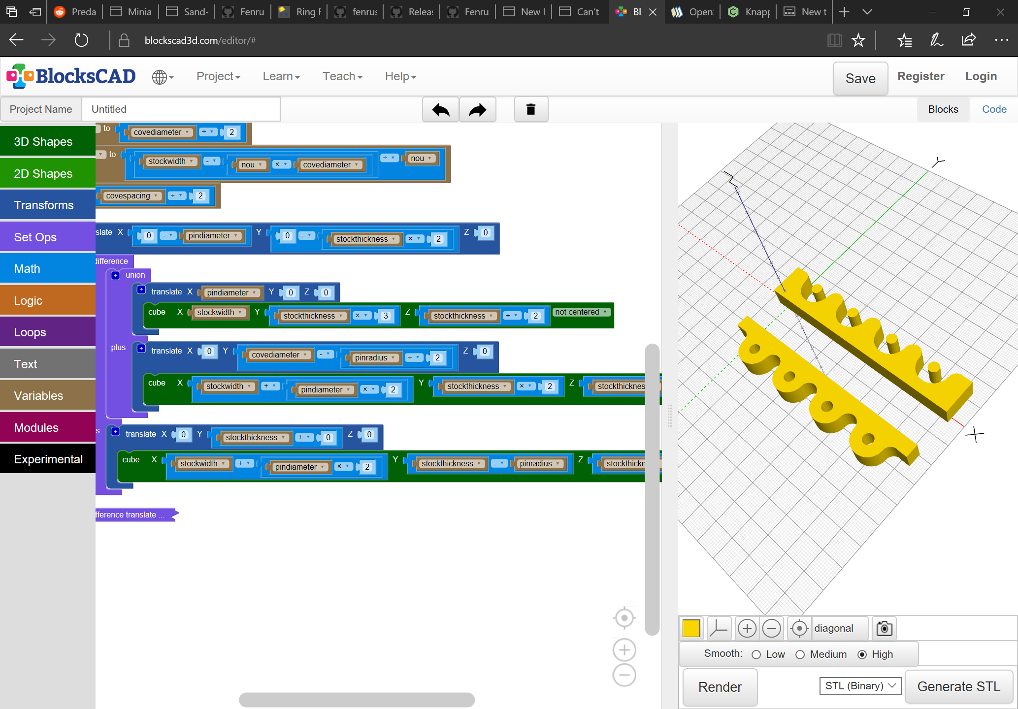
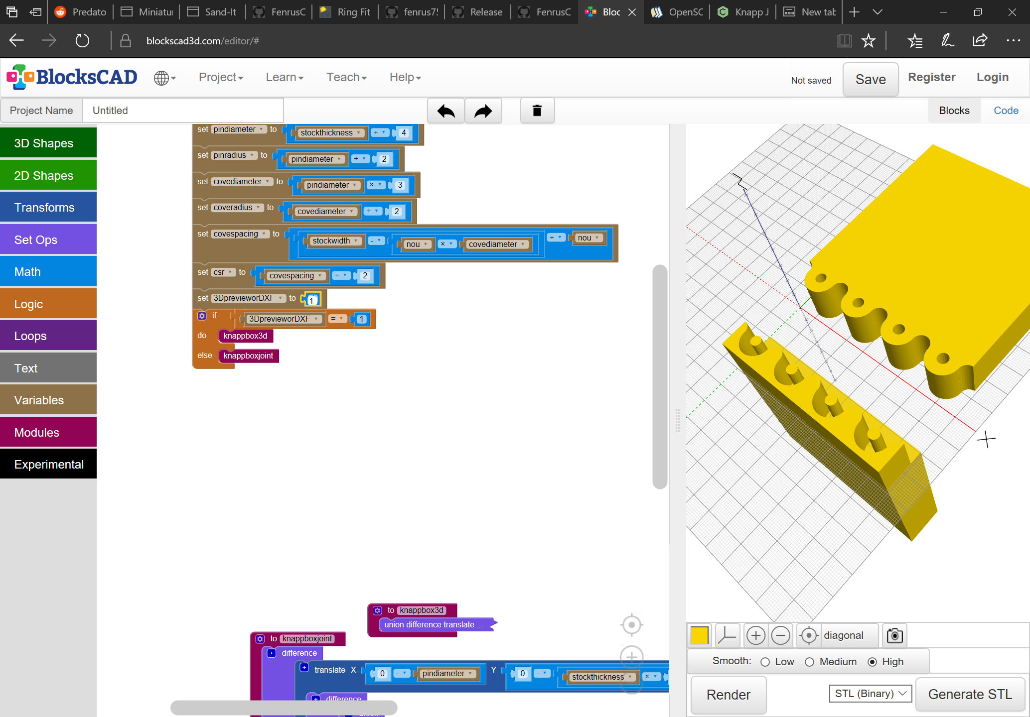
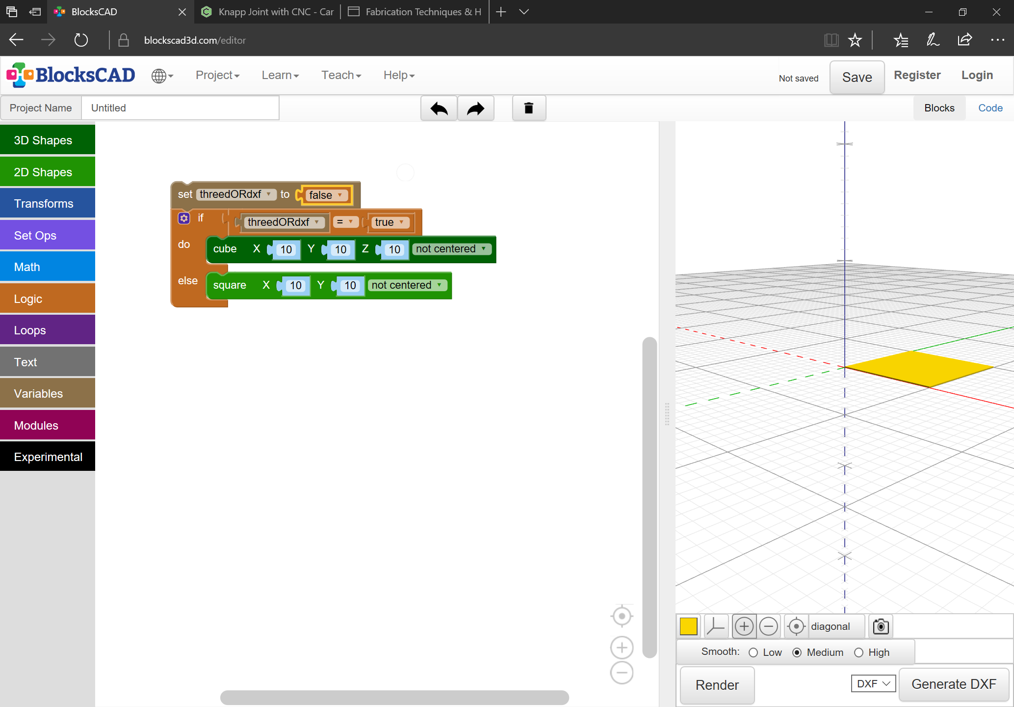
Turns out one can toggle BlockSCAD from 3D to 2D:
Next up is a version of the program which will take advantage of that and allow one to easily get a DXF.
Except, it seems the feature isn’t complete or something — I put in a ticket on GitHub — but if someone can show me how to do something other than place one of four shapes or text I’d be glad to know.