Over the past year and a bit I have been faffing with limit switches. My shapeoko didn’t come with them (early model).
I started my journey with micro switches, moved to slightly larger ones then onto hall effect magnetic sensors, I then tried some proximity switches with no luck, however I now have a full set of working proximity switches. The trick was to use a lower voltage.
The beauty of proximity switches is there is no contact - it detects the metal body of the machine and is powered through a 5v pin like the touch probe
I did a quick video for anyone who wants to take a look.
here are the limit switches I ordered in case anyone wants to have a go - importantly they are NO and 6-36V and have a pretty light on them
If anyone wants the design for the Y axis mount here it is:
My Z axis mount is unique to my Z axis so I won’t share that and X is mounted with hot glue, although I might change this shortly, if I do I will update.
I speculate it’s a combination, firstly the magnetic sensors I used were rated at 10-30 volts there is speculation that running this type of sensor on a lower voltage decreases its accuracy due to not being fully powered.
Secondally and combined with the above when mounted straight on they should be ok, but going when mounted sideways the magnetic fields vary more meaning they can be triggered slightly earlier or later.
Whilst I can’t confirm the above as fact I can say each time I homed my machine and returned to a work piece it was off my a fraction (usually 0. Something of a mm).
With the proximity sensors I’m getting Higher accuracy when returning to jobs. It’s worth noting this likely wouldn’t be an issue when milling signs, wood etc but allot of my parts are aluminium. I also made sure all sensors were mounted to trigger head on.
Thank you for the video. I would like to take up your offer for more info.
I have just placed an order using the ebay link you provided. Probably going to take a while before I get them. However i might as well try and understand what I’m doing before they get here.
Can you explain which wires (colours) from the switch go where on the board / supply?
What 5v supply did you use.
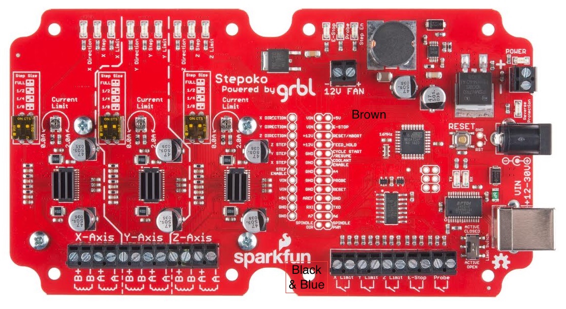
I now have my proximity switches. Instead of attaching the brown to +5v. Can I attach it to +12v which is a screw terminal and connected to a optional fan (not used) and always powered?
I am having problems. Just connected a single proximity switch (X Limit)
Connected Blue & Black to the connection at the bottom of the board board and Brown on the +5v . Then put a screw driver close to the proximity switch, but nothing happens.
Also tried to swap Black and blue around.
If I put a multimeter on Black and Blue. Should I see a voltage?
Do I need to enter something into the GRBL settings?