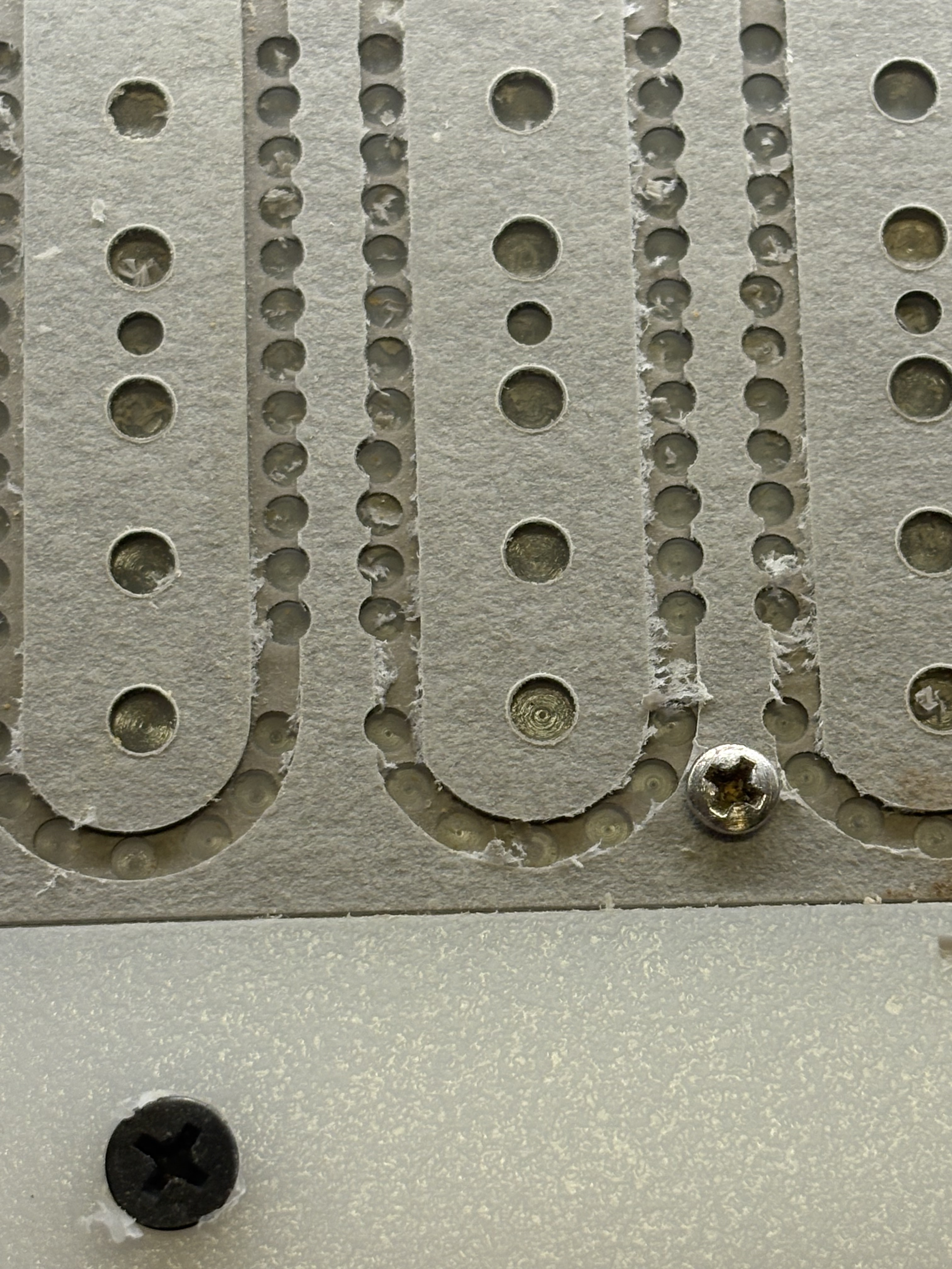
I am having an issue where I draw a linear array of holes to hog out material a later tool path will cut along and a repeating pattern of the holes will be drilled off center to the line. Alternately in an array of 3 central holes in the design the last one will drill off center. The entire part is slightly offset to one side to the centerline too. All is straight and precise in CC, I think there must be information driving the g-code to populate wrong. See pics:


Check the G-code. I bet it matches your positions in CC precisely. It’s most likely your machine. Slop, runout…
2 Likes
I’ve found for large complex project which may run into the limits of the machine, the best thing to do is to initially set up all the toolpaths to cut quite shallowly — if there’s any mechanical interference when running the file, it then becomes obvious and one can address it, then surface of the stock for a second run, iterating until one gets a clean run (or is in danger of making the stock too thin — that only happened once, it was a long night).
1 Like
Machine has 13hrs on it and everything is square and tight, because it is happening in repeating patterns of error (alternating 4 holes out of line on one, 7 holes out of line on the next) it seems like the g code gets an error in it to make that happen. At first I thought maybe it was losing steps, so I dropped the feed rate way down (10), but it’s not the whole thing that is off, it has a pattern.
Tool paths are set to cut shallow, material is vulcanized fiberboard, work is held solid to work holder and holder to the waste board. I feel like the g-code is being generated slightly off because of how tightly I am spacing things? Sometimes the center hole in the part will drill out of line to the three holes to either side of it, and they are all plotted on the same line exactly.
Are feeds and speeds appropriate to the material/tooling?
You can check the G-code. It’s man readable ascii text. You can also load it into a analysis/simulation software & verify it. You can simulate it in CC, and turn off the simulation so you’re only seeing the toolpath. rotate to a side view & see if every 4th one is off.
Of all the Gcode files I’ve checked, they were never more than 0.001" off.
Yeah, like 10.0 in/min making .020” deep passes on the continuous cuts, plunge 8.0 and feed 10.0 for drilling the arrays. Machine has 65mm spindle/vfd.
Strange, it seems the pattern of the 4 holes and 5 holes offset repeat somewhat consistently. The one off of the three holes in the center are no at as consistent. We have seen a few cases where the wrong selection of offset was used, inside/outside or on the line selected for the vector. Also several cases of incorrect selected vectors on several different layers that repeat the exact same tool paths.
The last thing would be a potential mechanical interference of some sort on the axis’s.
Thank you for the info. I have been adding tools to my library as I use a lot of odd sizes, 3/32, 1/8 o flute, 5/32, 3/16 etc, I think this may be where the issue lies, all of the new tools had the finish tolerance set to 0.1”, edited them all to .001”. We will see.
1 Like
What software are you using? Pretty sure CC just has built-in, hard-coded tolerances.
Although it would be cool to enter our own.
1 Like
CC PRO, when adding tools to the library, “finishing allowance” sorry, not tolerance, was set to .1” which is quite a lot.
That’s odd. Finish Allowance should only apply to 3D roughing paths, if the parameter is even used at all. Just checked, it uses 0.5mm (0.0197") no matter which tool you choose.
3 Likes
Hmmmmm. Yeah. I thought I had something but no. Talking to Carbide support about it.
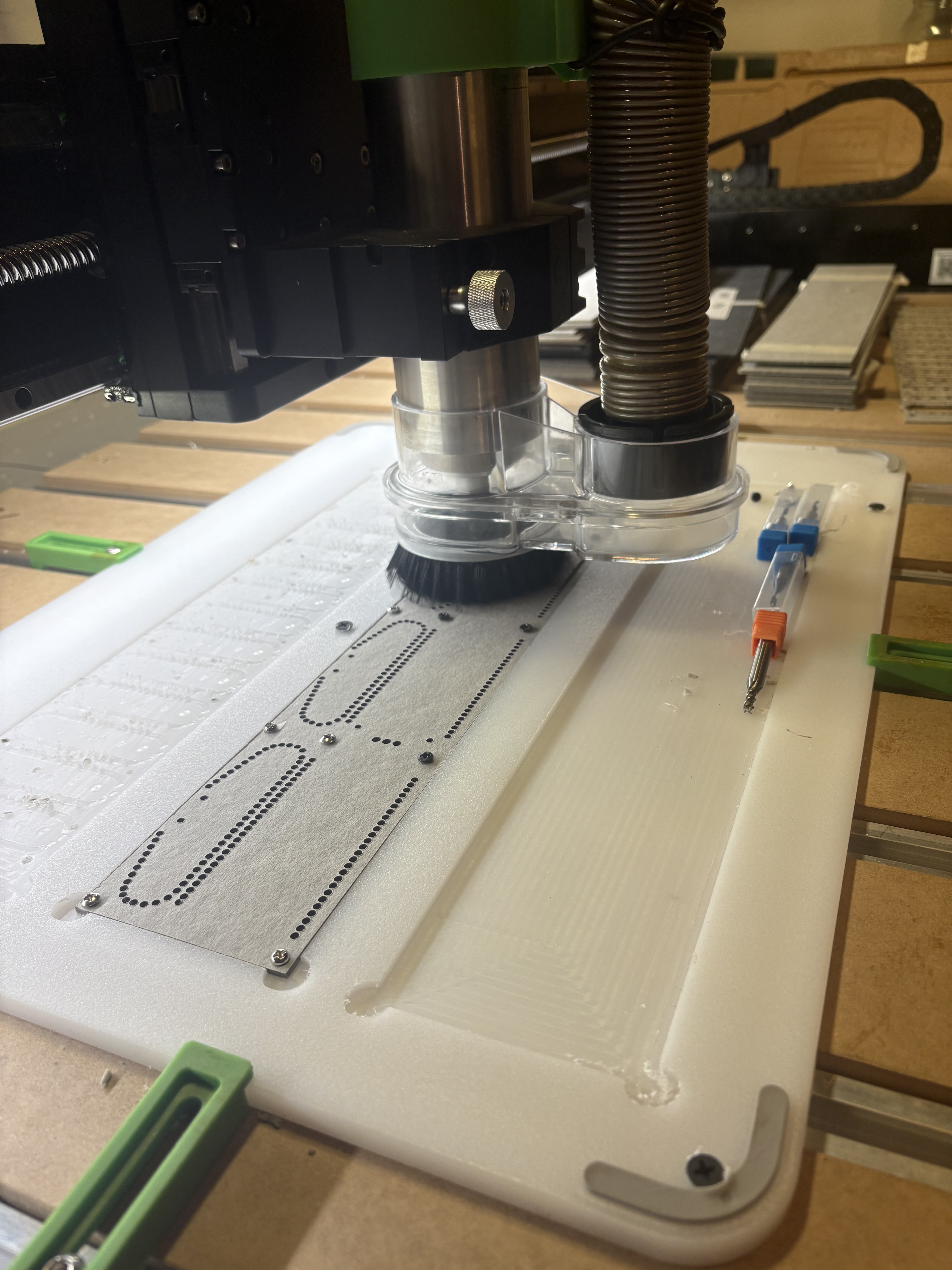
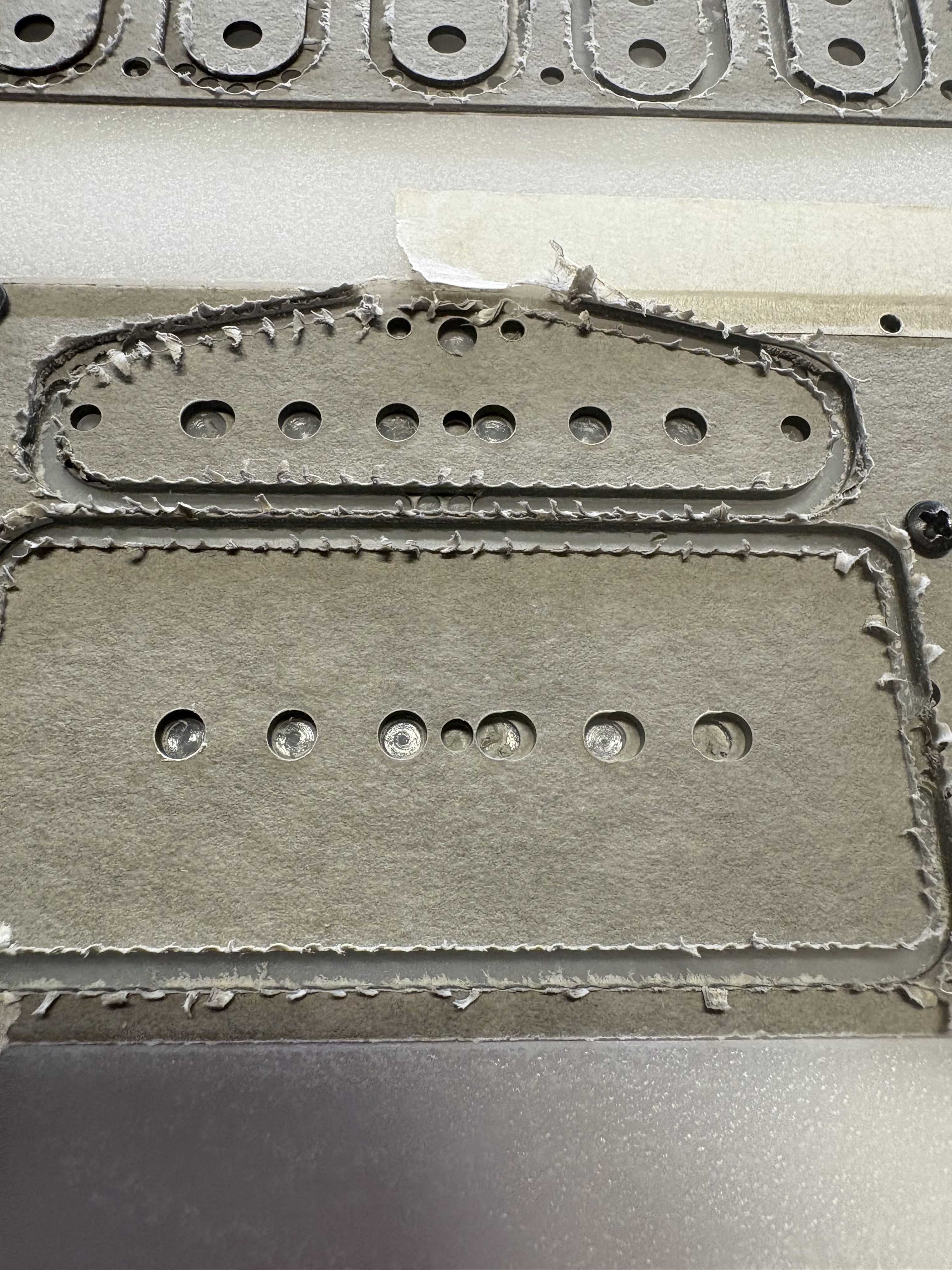
I had other stuff to cut so I tried this out, drill arrays went well long sides laid out horizontally, it is definitely more of an issue when they run vertically, as seen in earlier pics, but the elements aligned vertically in the design got wonky and the centers of the larger holes in the middle (these are guitar pickup flatwork) meant to hold rod magnets where I am making a full depth cut 5/32” followed by a mid depth 3/16 cut got off center too. There are 4 tool changes, I could have a better hose and hanger for the vacuum. I think this may have an effect on things skipping a step, but still doesn’t explain vertical alignment issues within the same drilling tool path stepping out of line.
More than happy to have eyes look over my c2d files, I’m just picking this up and trying to be thorough but still not 100% up to speed on all the particulars of CC Pro, and deeply experimenting how to best cut this material without just going to a CO2 laser specifically to cut flatwork sooner than later. I have plenty of wood guitar-related things to do that this machine is great for, cutting flatwork is the current big workload I want to do with it until I have a little more space to have a machine room in the spring where a bigger laser will fit. Really appreciate all the input thus far.
For the last image you uploaded, can you also upload the c2d file used? Many here will look at it. Bozo
Slop in the z carrier ballscrew?
I came across the info here leading to videos on YouTube about the four screws that hold the z carrier to the ball screw and checked those, they are tight and the hdz was tight before removing. With the hdz removed from the carrier I have probably 1-2mm side to side play with mild effort, sort of a clunk before you’d have to push to overcome the opposing force to move it manually but it shifts,with a clunk, when you reach that limit.
Symptoms are as pictured but it was also cutting essentially rough and oblong holes, something I had thought maybe was more of an issue with the material, or the machine was just clunky with circles and a small bit. Noob troubleshooting.
Sized drilling should have ruled out those perceived issues. I have been using a 3/32”, 1/8”, 5/32”, and 3/16”. I thought maybe the tool changes were messing with things and the repeating patterns of offset are related to different sections of the tool path where within the same tool path a shift occurs so things get off when tool changes are not a factor as well. This made me think code error first, or skipping steps, or I am no good at making the file or too clickety with the track pad etc.
What amount of clunky side to side play is normal before actually manually moving the z carrier along the x? It makes me thing the preload is not right, but this is my first ballscrew outing, I’m learning as much as I can.
I can but I’ve been all over it, it’s very simple stuff, things are where they should be. I had dismissed excessive play/slop as Tod mentioned above because the machine is very new, followed assembly instructions precisely and had some initial success and failure from bozo/human file errors as to be expected. Now that I’m pretty sure the file is good and well thought out, checked, rechecked and revised for better efficiency, keeping tool changes to a minimum, it should be cutting a better product than it is.
Tod was right with slop. Within the same tool path some things being cut/drilled off center and other things not is seems most reflective of slop, and if slop is what a I’ve got in the hdz carrier bearing, how do I fix it?
I love the thing and I feel like I can use it to do this work and put off a laser purchase for a good while (small company, I chose this over a shop truck), a maintenance and repair manual would be a godsend w this guy as I want to baby it and keep it in good order for a long time.
Which machine? With the machine on, and the spindle off, can you move the cutter side/side, front/back? Check all fasteners/joints in the drive train. motors, couplers, drive gears, bearings, ball screws or belts. Especially end/thrust bearings.
Whichever machine, you should be able to get good repeatable cuts with tolerances of less than 0.001" for ball screws/lead screws. Not sure for belts, but properly tuned I expect better than ±0.005"
1 Like
It may very well be slop. I assume when you looked over your file you scrutinized not only precision of the drawing but the tool path applied as well. Your initial uploaded images show a definite pattern to the errant cuts. If this pattern is due to slop in the machine, it should correlate with directional changes in the tool path/carriage travel. If the correlation exists, its nature can help pinpoint the source of the mechanical issue. Cheers. Bozo
1 Like