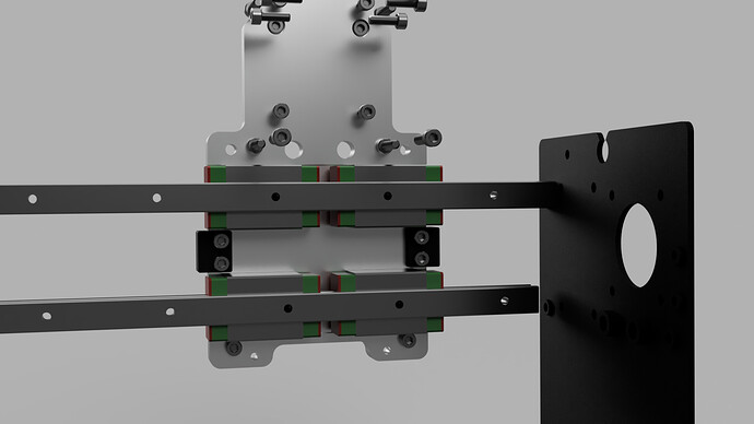
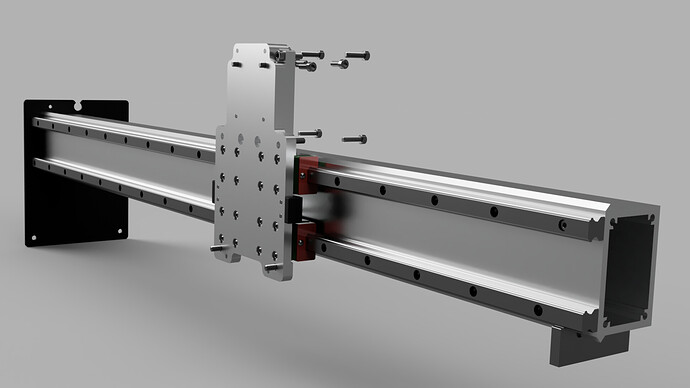
So have made the decision to add linear rails to my X axis on my SO3XL the rails I have are 1000mm HGH20s. I have the to put two rails parallel and attach the blocks on a back plate for my Z axis. The only issue I have is that if I attach two blocks per rail the blocks will stick out a little more than half an inch on each side of my Z slide. I am wondering how much of a disadvantage or issue it would cause only having a single block per rail would cause? I cant return the rails and exchange them for HGH15 because I bought them at going out of business sale. I’m wondering if @RoughDraft40 or @Vince.Fab have any input or around here anymore. I’ve seen they have some experience with adding rails to the machine.
Hey Anthony,
I’m a mech. engineer, but I’m not an expert in engineering bench top CNCs by any means so take my advice with a grain of salt.
There are lots of ways to go here - if you’re dead set on the 20mm rails, I would see what other configurations can be made on the whole system to make two sets of blocks on each rail work. The single block top-bottom seems like it would be susceptible to succumbing to lateral cutting forces from the larger moment forces.
It might be worth your while to check out THK’s Calculating The Applied Load for rail bearing blocks. I just found it on a quick search.
What are you typically cutting with your machine?
Are you planning on flipping your Y-end plates?
What kind of resources do you have (time/money) to maybe experiment?
Are you fabricating the adapter plates yourself?
I’d be interested in what @LiamN has to say since he’s been wringing his machine out for performance while making critical assessments/observations.
The purpose of two blocks is mainly to deal with torque. Linear rail blocks are very good at dealing with regular linear pushing/pulling forces that are directed perpendicular to the rail, but they’re not great with rotational forces.
But if you take two of those blocks and put them on the same rail, you can still rotate them around the rail but rotating them any other way is very difficult, because to rotate one, you have to push/pull on the other.
The remaining problematic axis (rotation around the rail) can be resolved in a similar way by adding another parallel rail.
If you look at the data sheets, they should give you the torque ratings for the blocks, both on their own and in pairs.
Aside from two blocks, another possible improvement is longer blocks. Some manufacturers offer different size blocks for the same rail profile. They should list the torque ratings for these too.
Yep,
Everything Brian says is sensible there.
I used Dan Story’s CAD design as the basis for my X conversion too. The adapter plate to mount HDZ onto the rail blocks was a really useful place to start and saved me several rounds of prototyping. I still have V wheels on the Y plates and my machine is hugely improved, my measurements suggested and confirmed that most of the deflection is due to the X-Z V wheels.
As Brian and Lucas say, you may lose rather a lot of rotational stiffness if you only use one block per rail, you may just have to accept the reduction in X travel.
The alternative (again, as Brian says) is to ‘go pro’ and flip your Y plates to the outside of the rails on your machine, you can rotate the Y rails to put the V wheels on the outside. However, this would mean you need to find a new extrusion long enough to bridge between those outer mounted Y plates and also, if your rails are only 1000mm they probably don’t have the spare length anyway (The CAD says mine were 1016mm on my XXL).
Realistically, as you’ve found, there’s not much room left for longer blocks behind the Z adapter plate and you’ll find the rails need to stop short of the Y plate to clear the V wheel bolt points as well.
This second pic has the small alignment bracket I made a pair of for aligning the lower linear rail to the bottom side of the X rail which made assembly a little easier, I also put an alignment edge on the bracket plate to align both lower bearging blocks. The upper blocks and rail then became the parts that got adjusted during assembly.
Thank you guys for the fast replies. I am wanting to cut more aluminum, resins, and harder woods. Im a CNC lathe machinist and programmer by trade and at my shop I’ve been given the go ahead to make the adapter plates as well as using any other tooling at work that I dont have at my home shop. Im not dead set on using the 20mm rails on the X axis, I just got a good price for them and the shapeoko upgrade is the only project I have that they could work for. I most likely get a set of 15s for the X axis. When it comes to resources buying another set of rail will have to wait while I do the responsible thing and continue to pay bills, I have been slowly upgrading the machine bit by bit.
From the looks of it I’ll have room for the double blocks per rail on the Y axis, which I was plaining on adding as well. @DanStory do you have any pointers on the adapter plates you made for yours. I have looked around and the ones I see that you use will work the best.
This topic was automatically closed after 30 days. New replies are no longer allowed.

