I’ve been wanting to build a modular book shelving system for a while now. Now that I have a CNC, that’s within reach? I’m limited to 2x4. I’d like to cut all pieces from a quarter sheet of 3/4 birch ply. I’d like simple joinery, minimal hardware and bracing. Modular boxes (like Ikea Kallex would rock). Any ideas on wjere I might find some designs… or ideas and hints on where I might start with a design of my own?
I’ve been looking at this for a while and have worked through some kind of odd ideas:
as well as some which are more prosaic:
A basic option is rabbets:
but that is not really suited to plywood.
There are a number of books on this sort of thing such as Design for CNC: Furniture Projects and Fabrication Technique by Gary Rohrbacher, Anne Filson, and Anna Kaziunas France
We’ve explored a fair number of joinery options here:
https://community.carbide3d.com/search?q=joinery
and I’ve pretty much settled on full-blind miter box joints as being the most expedient — downside is it requires a narrow 90 degree V tool and takes a bit of time to cut, for more on this see:
It’s going to be hard to come up with something which is as cost-effective as Ikea Kallax though, esp. with it having the open back which allows minimizing material usage.
A 3/4 in. x 2 ft. x 4 ft. PureBond Birch Plywood Project Panel is $31.46 at Home Depot at the moment:
If one needs to get:
- one back
- a top and bottom
- two sides
out of that, well the geometry is kind of limiting… hang on while I draw that up and do some figuring…
1 Like
As noted, if one is trying to get the whole thing out of a quarter sheet, then one needs 5 parts, something like:
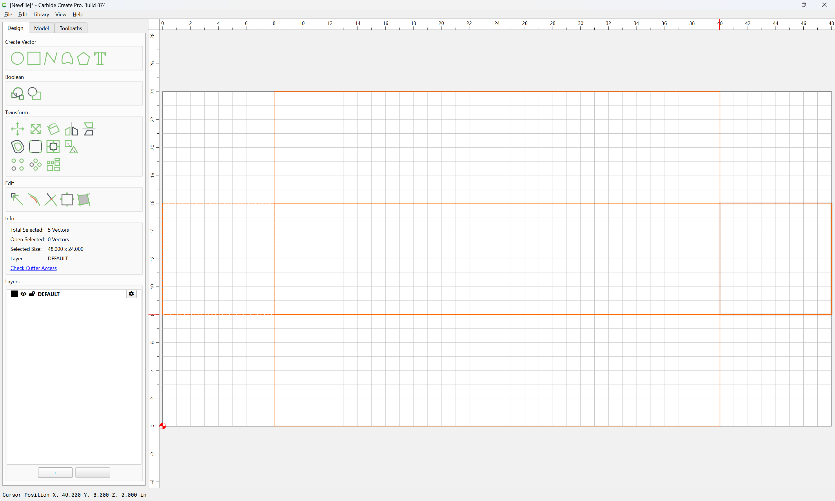
but that leaves a dimension for the back of:
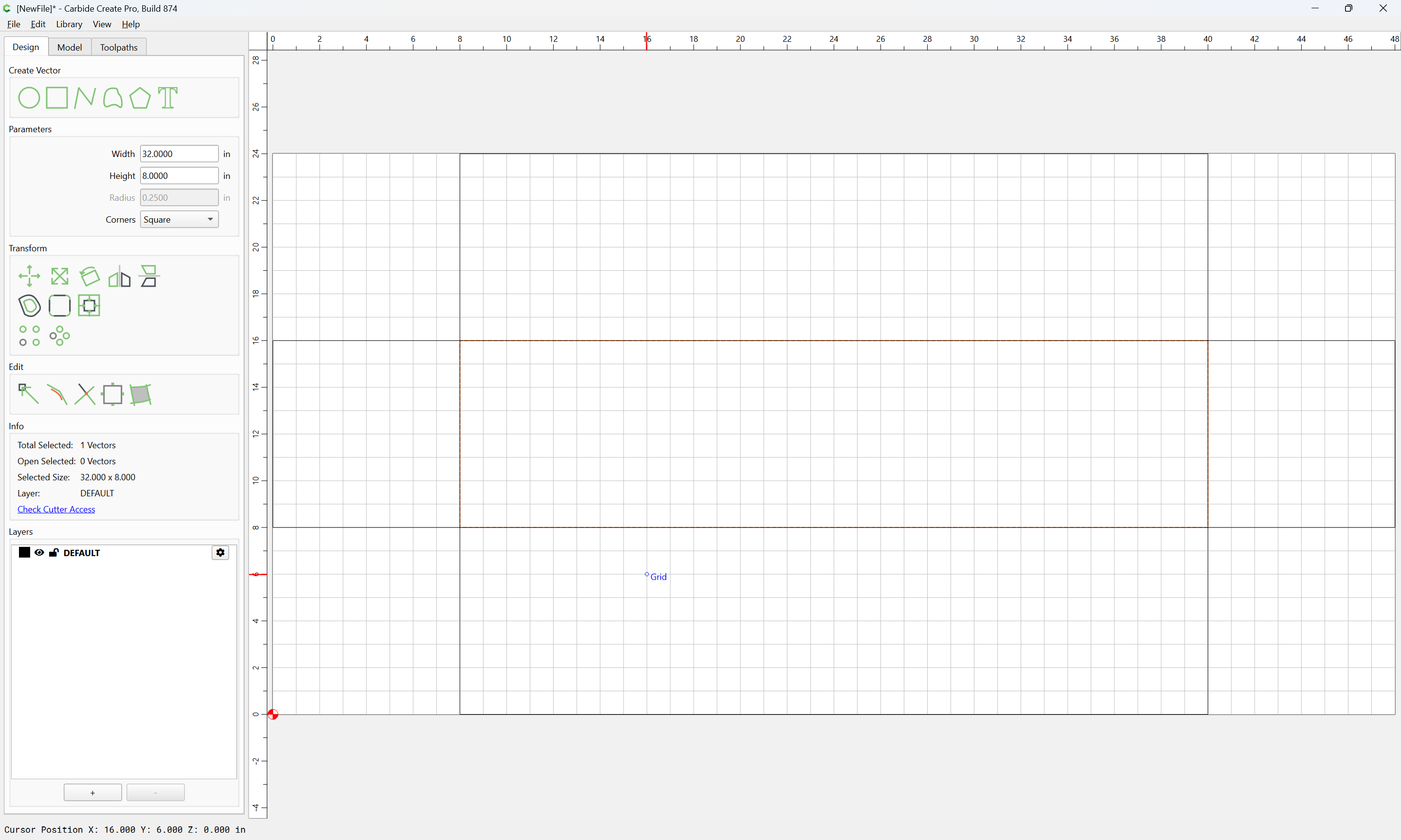
which won’t fit a paperback book… adjust for Mass Market Paperback size of 7 x 4.25" or so we instead arrive at:
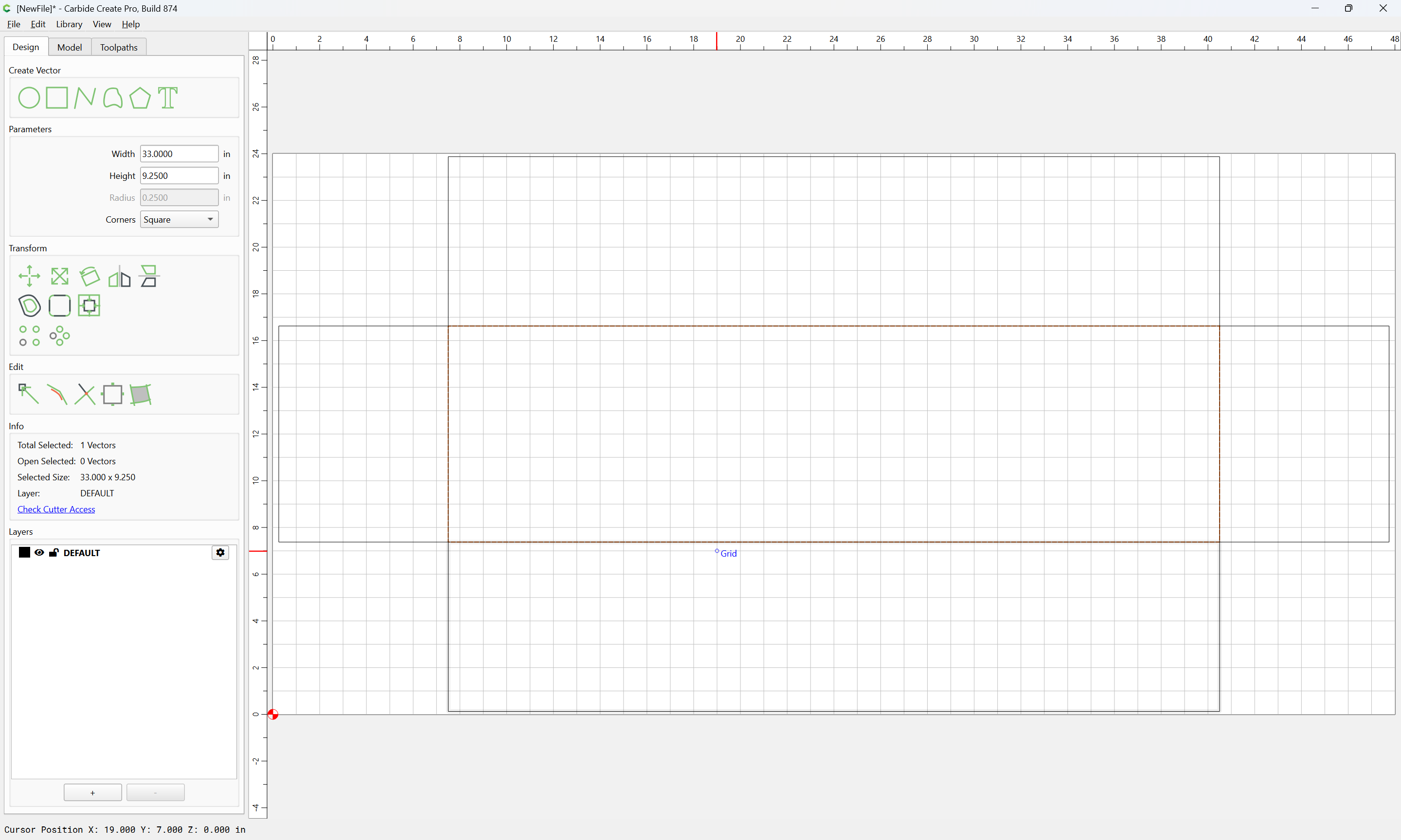
which seems pretty workable and leaves one a quarter inch or so all around for margin.
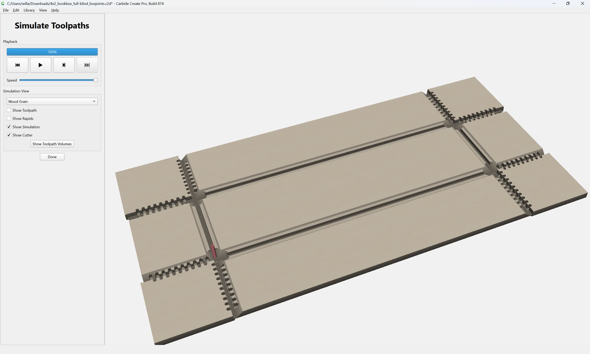
Cutting full-blind box joints into this is pretty straight-forward, we simply need a couple of toolpaths:
- full-depth 8mm 90 degree V tool to define the edges of the miters
- partial depth 8mm square tool cuts define the box joints
- a shallow depth set of cuts at the top to define the top edge of the joints
- a series of graduated cuts at the corners to define the miters
Start by setting up a layer for the full-depth 8mm 90 degree V:
and make it the active layer:
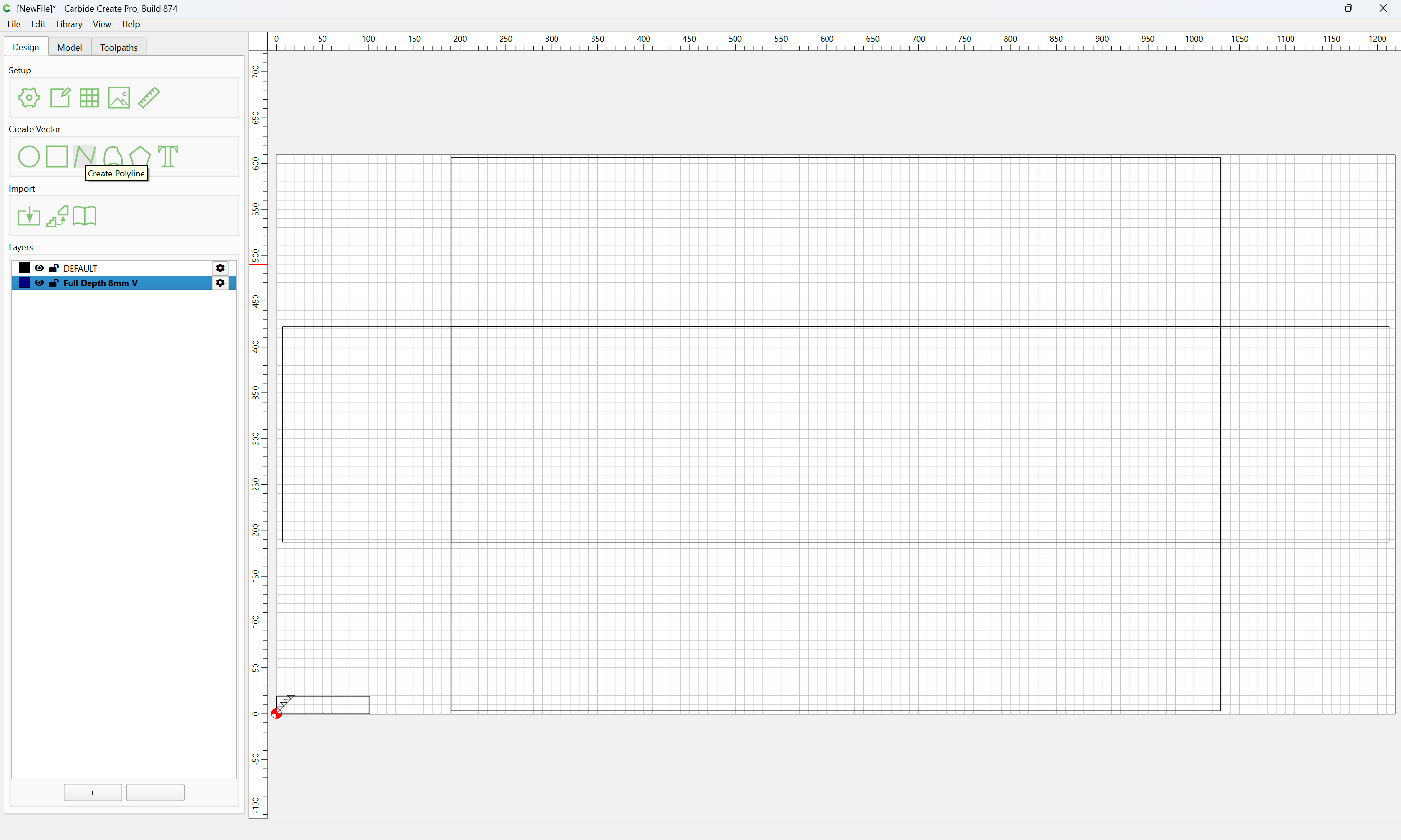
Then draw a series of lines which traces out all edges which need to be cut for the joinery:
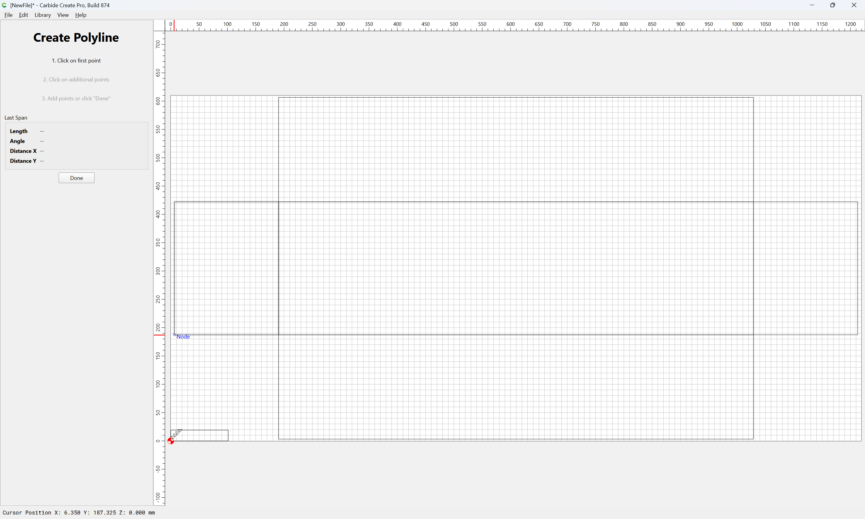
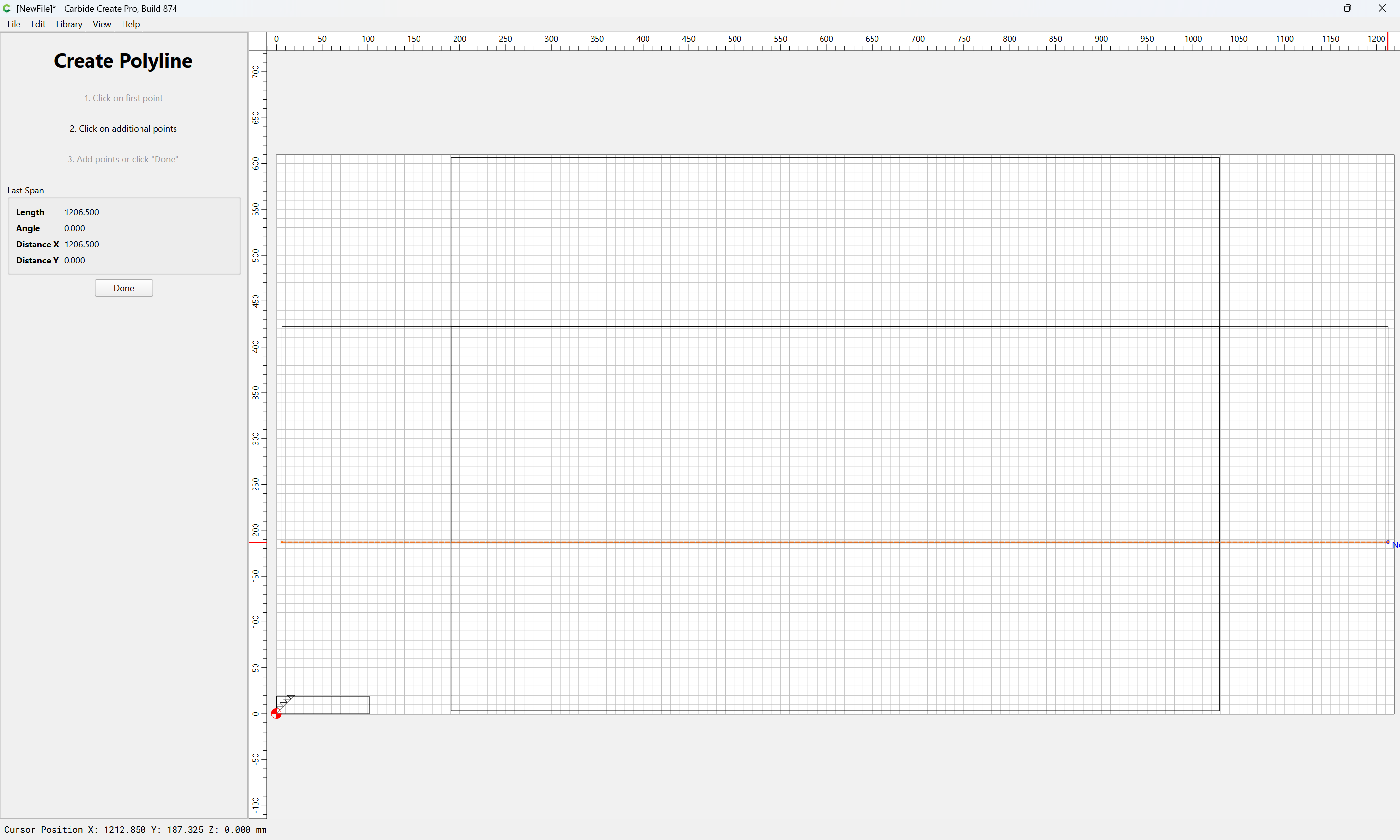

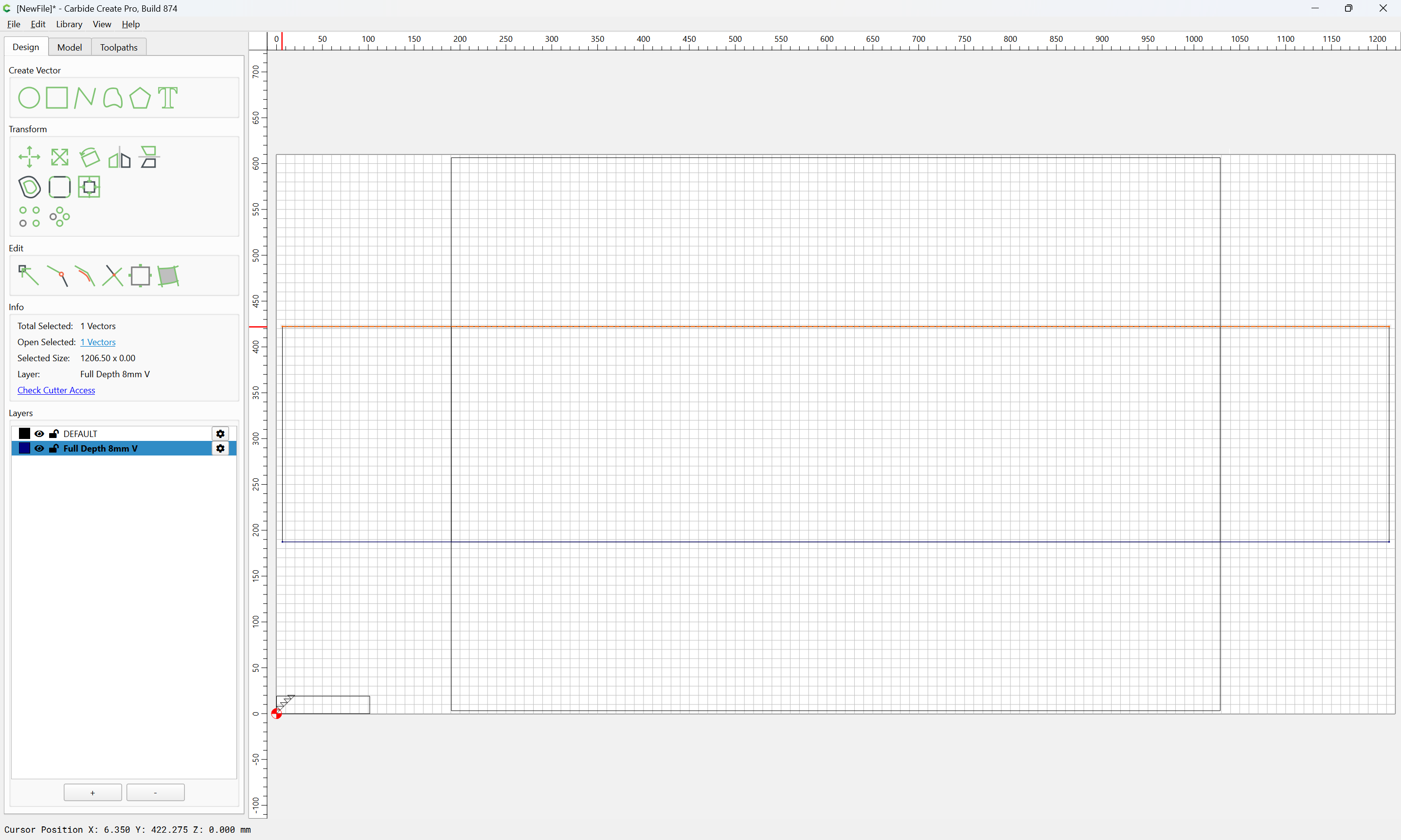
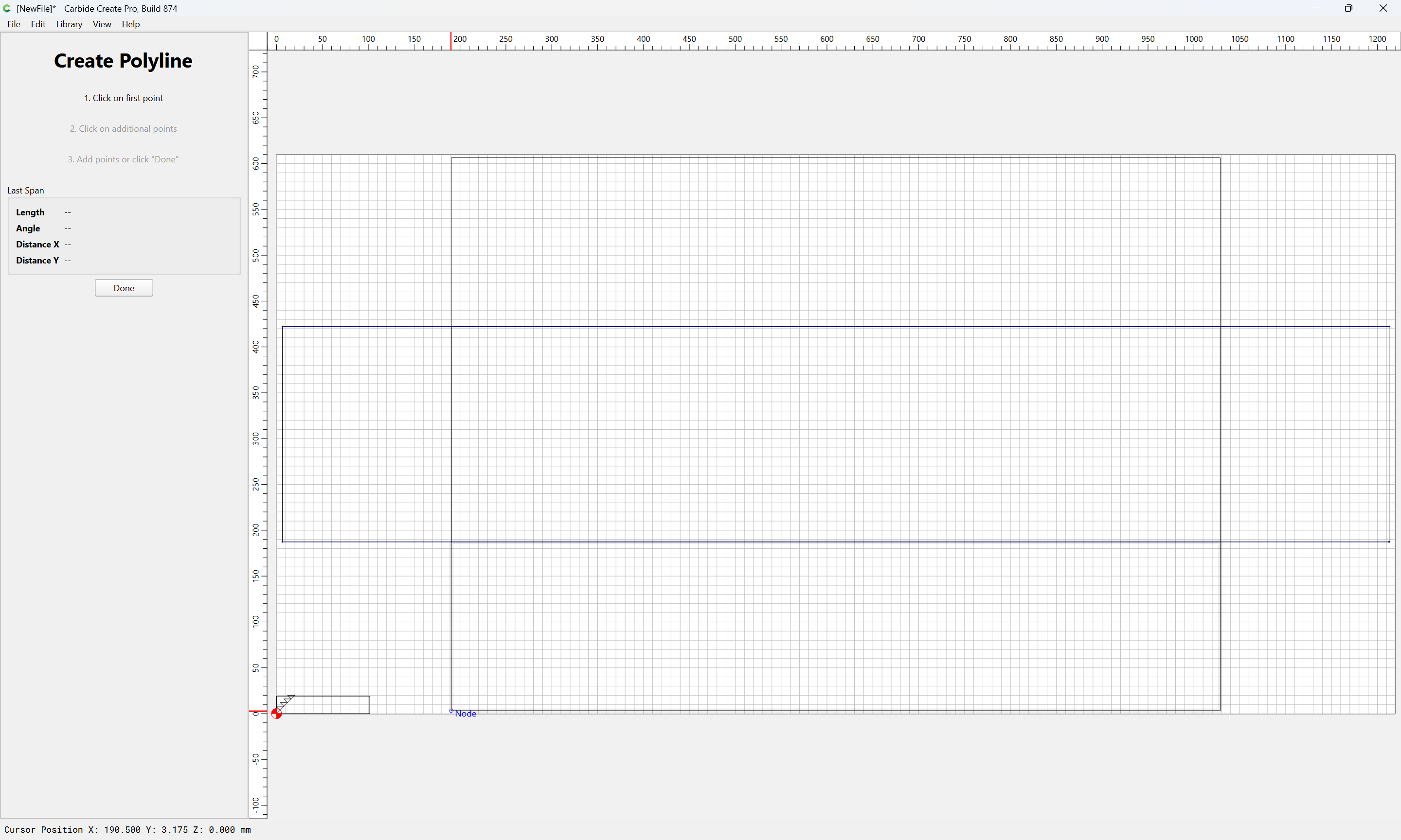
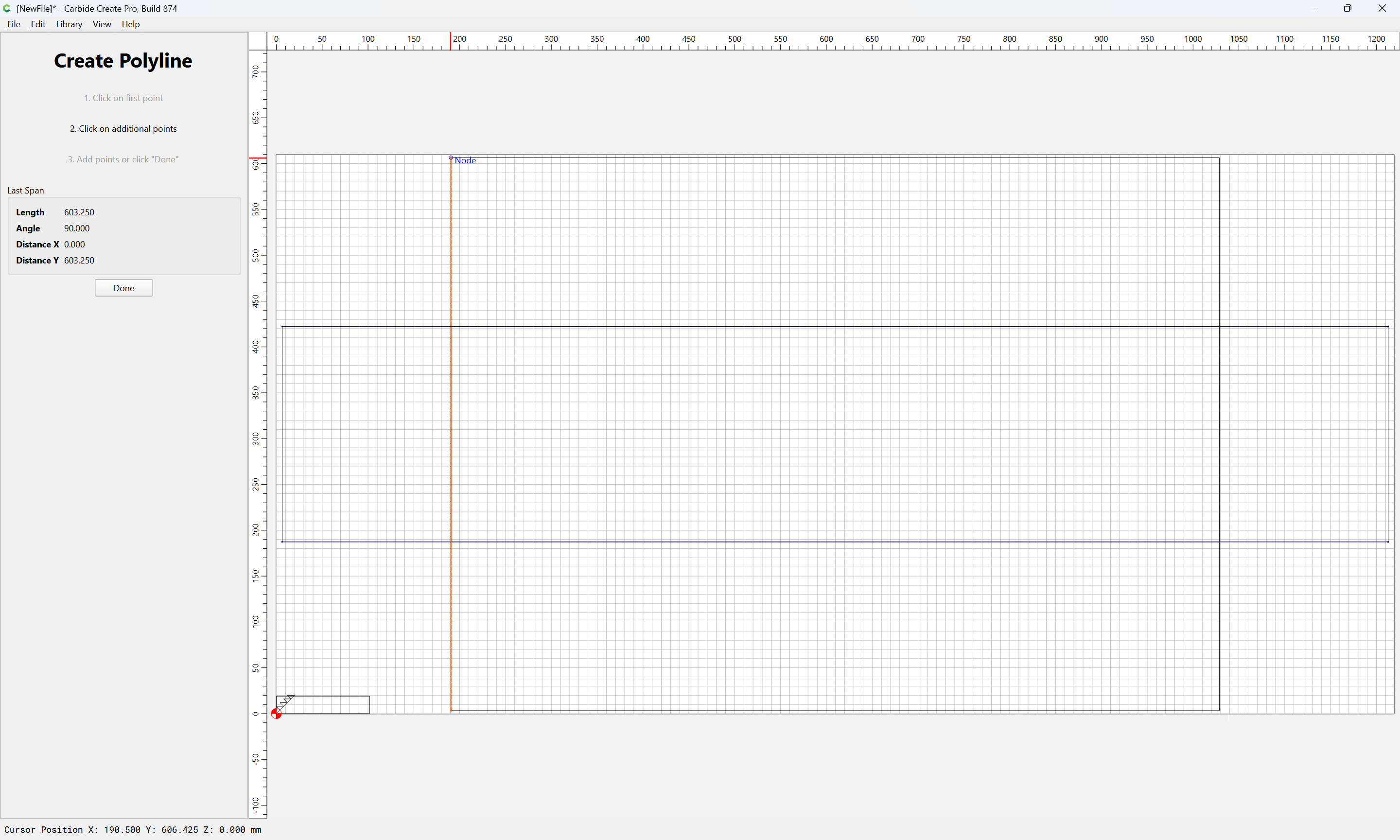
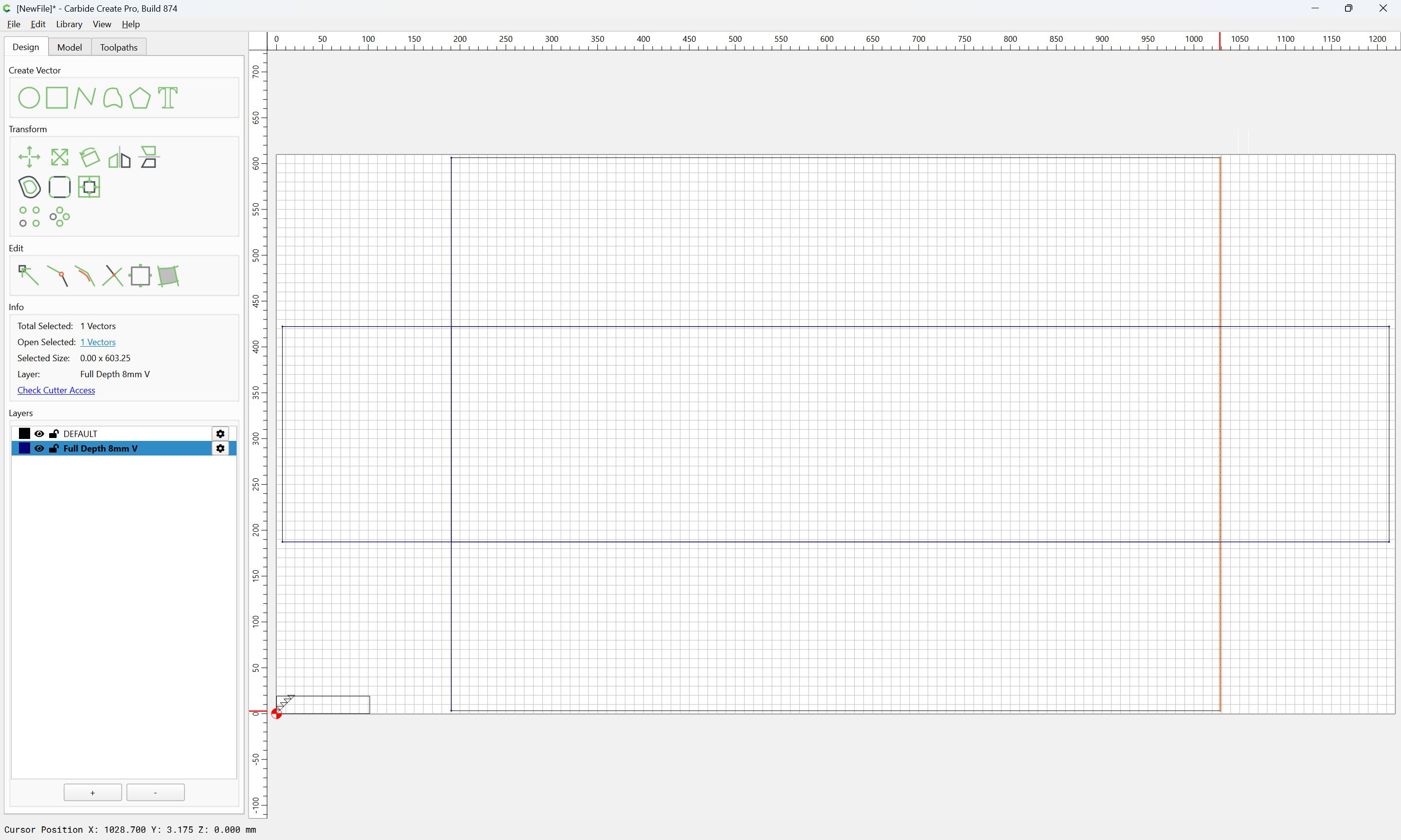
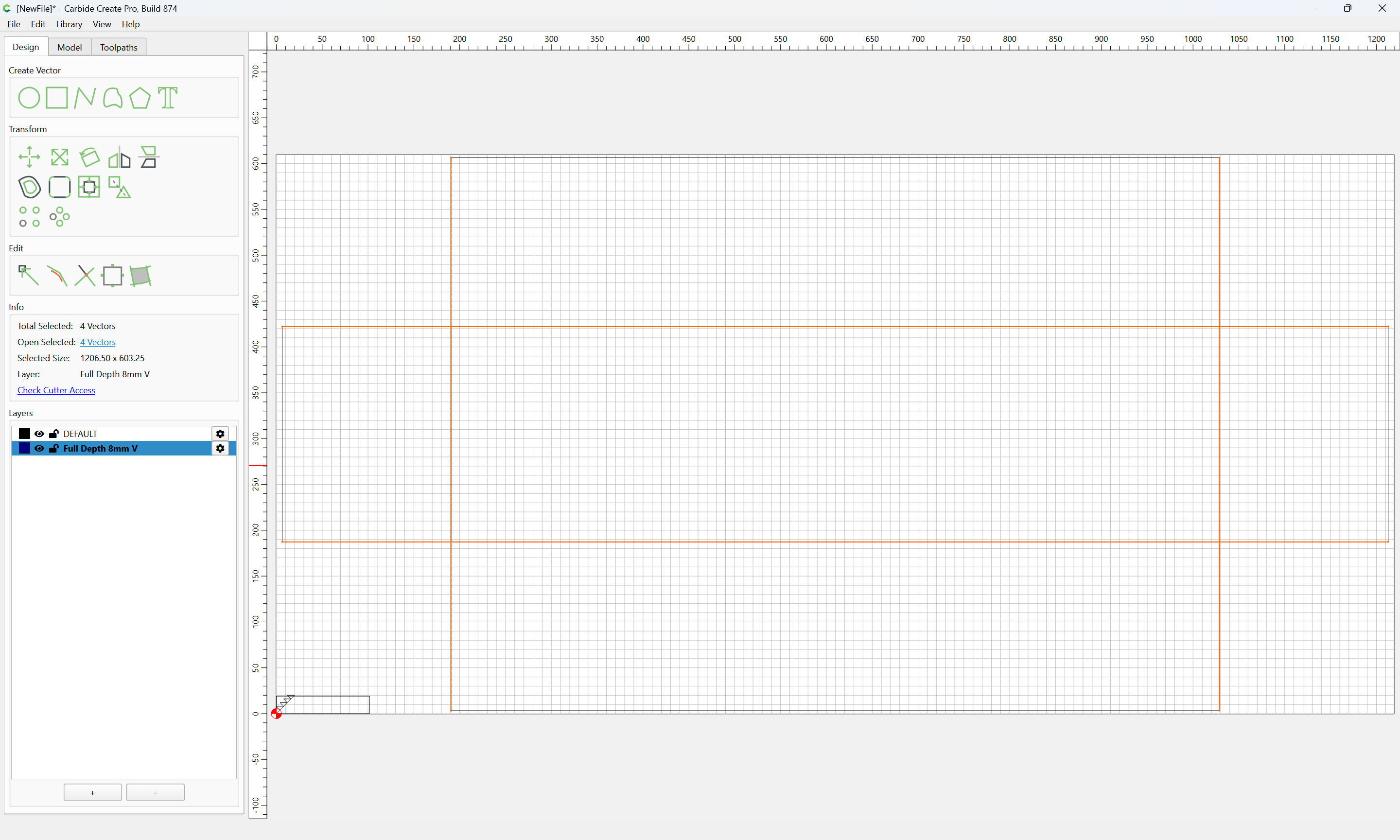
Then assign a V tool to cut to that depth:
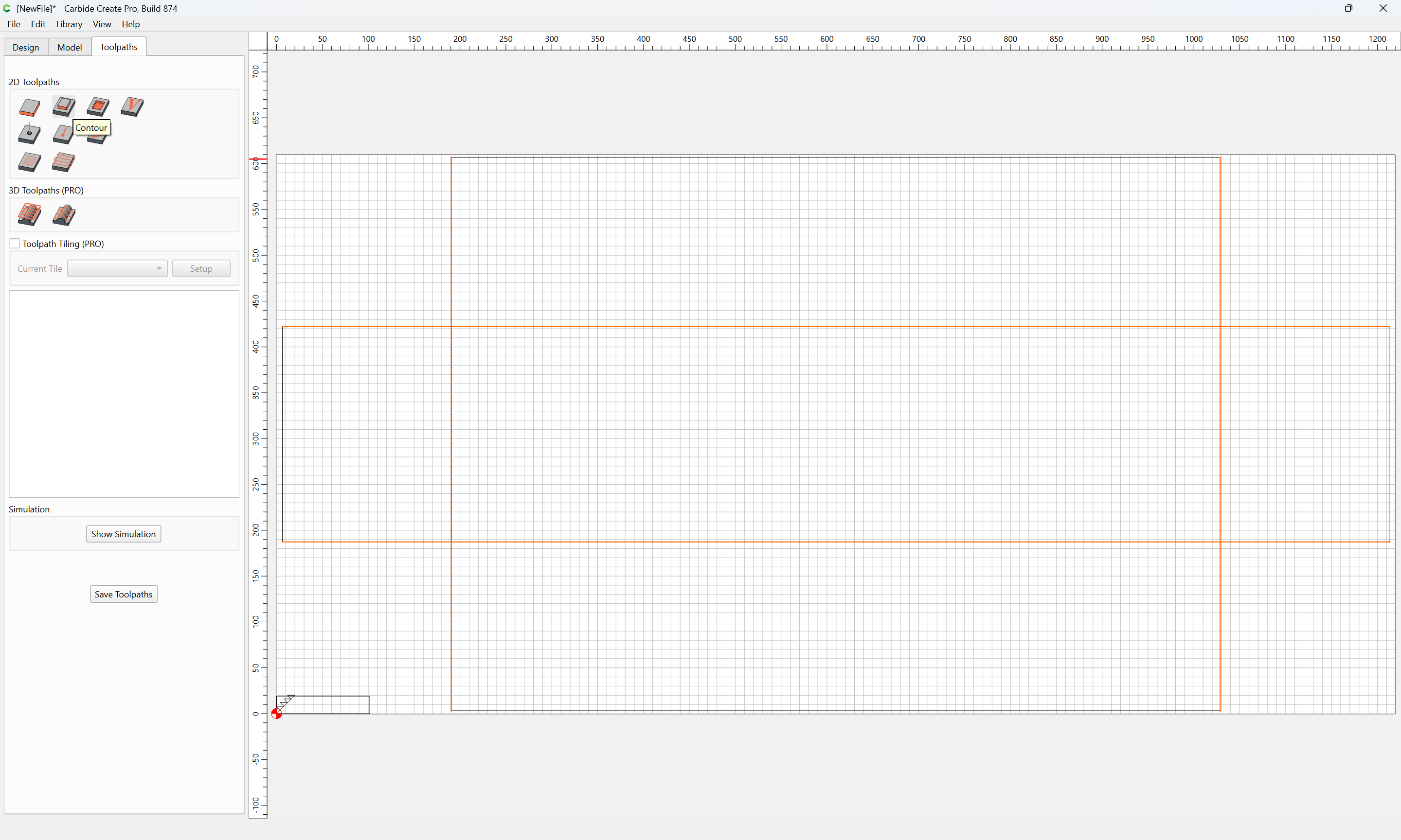
Select by Layer
h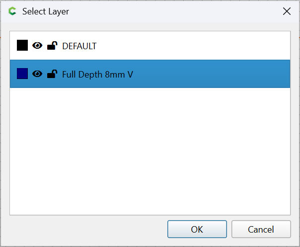
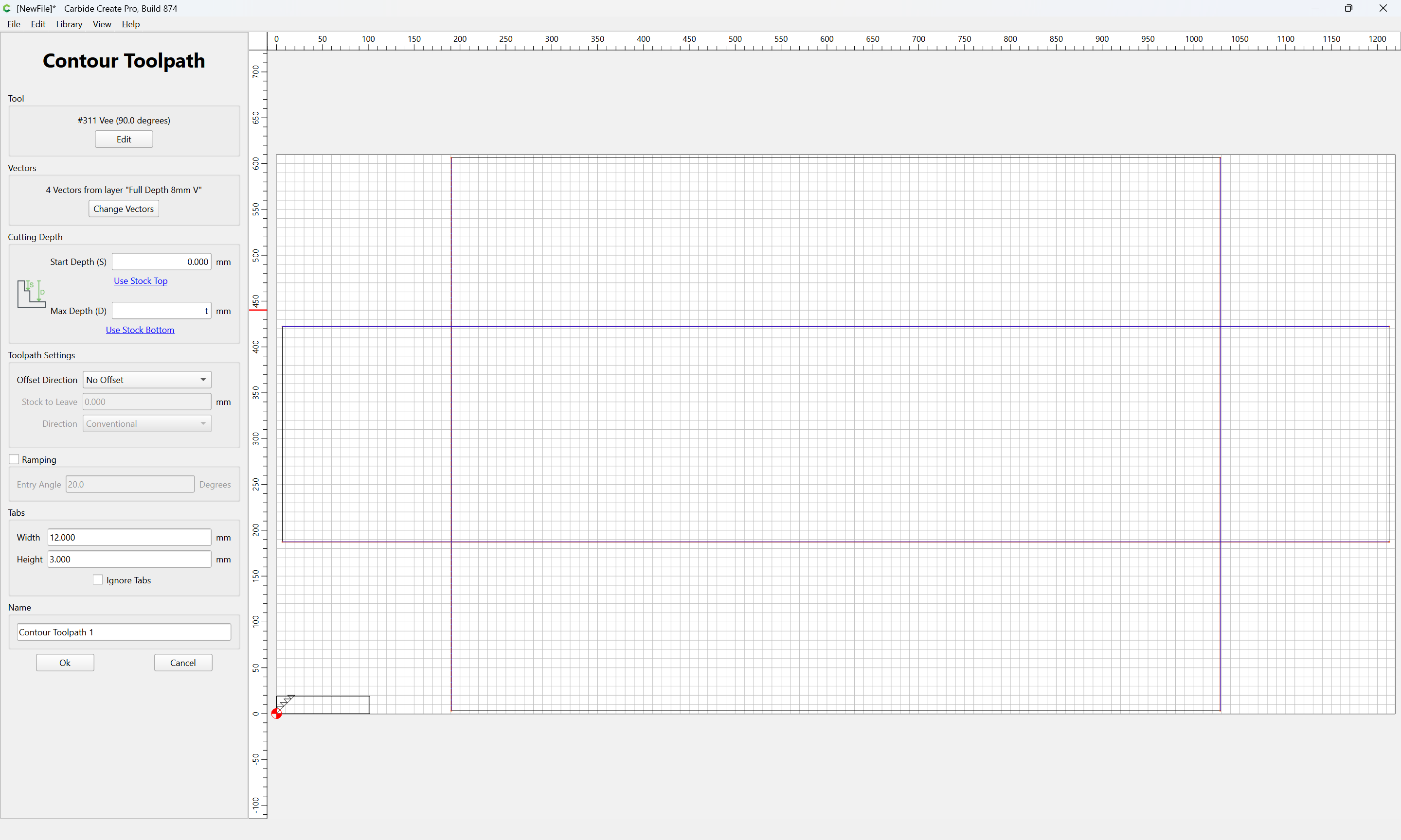
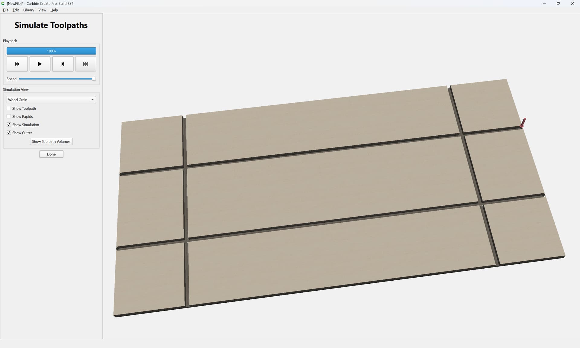
which previews as:
Then, draw up the tooling which will be used and the stock in profile:
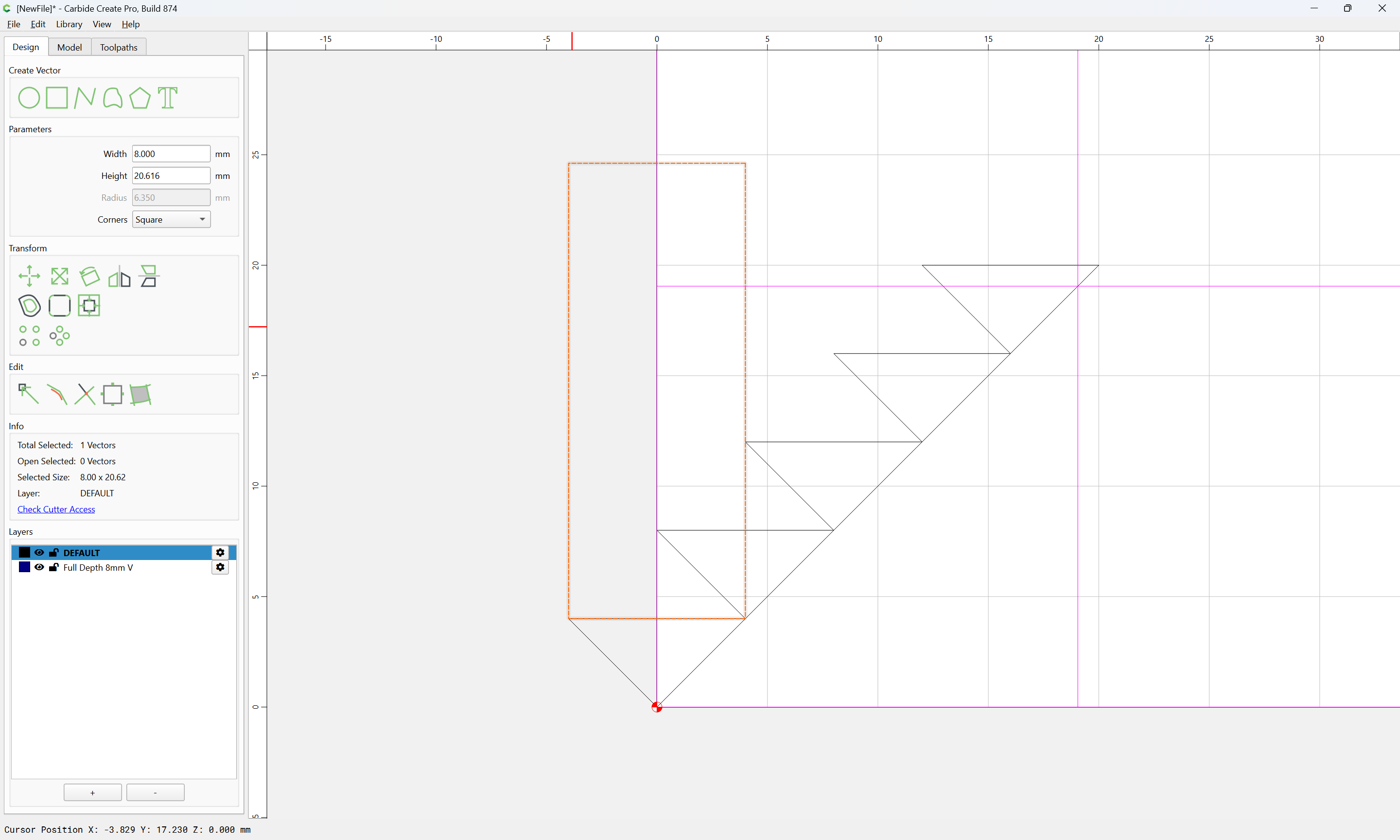
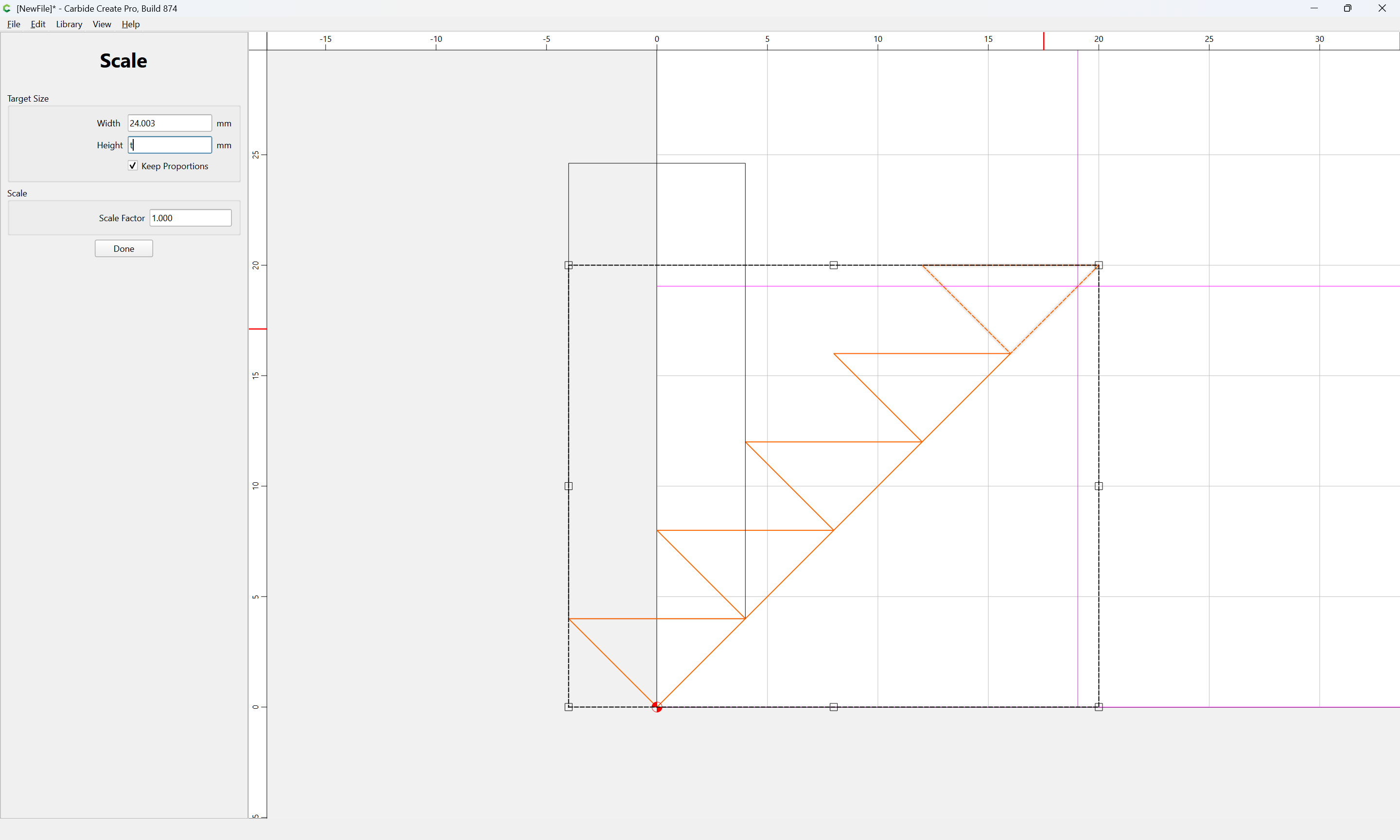
One somewhat tedious aspect will be to make multiple cuts using a V-tool at the corners so as to define the full-blind miter — if the tool is markedly larger relative to the thickness of the stock this is a bit easier, as it is, at least 5 such cuts at different depths will be necessary — selecting the 5 V-tool profiles:

we scale them to the thickness of the stock:
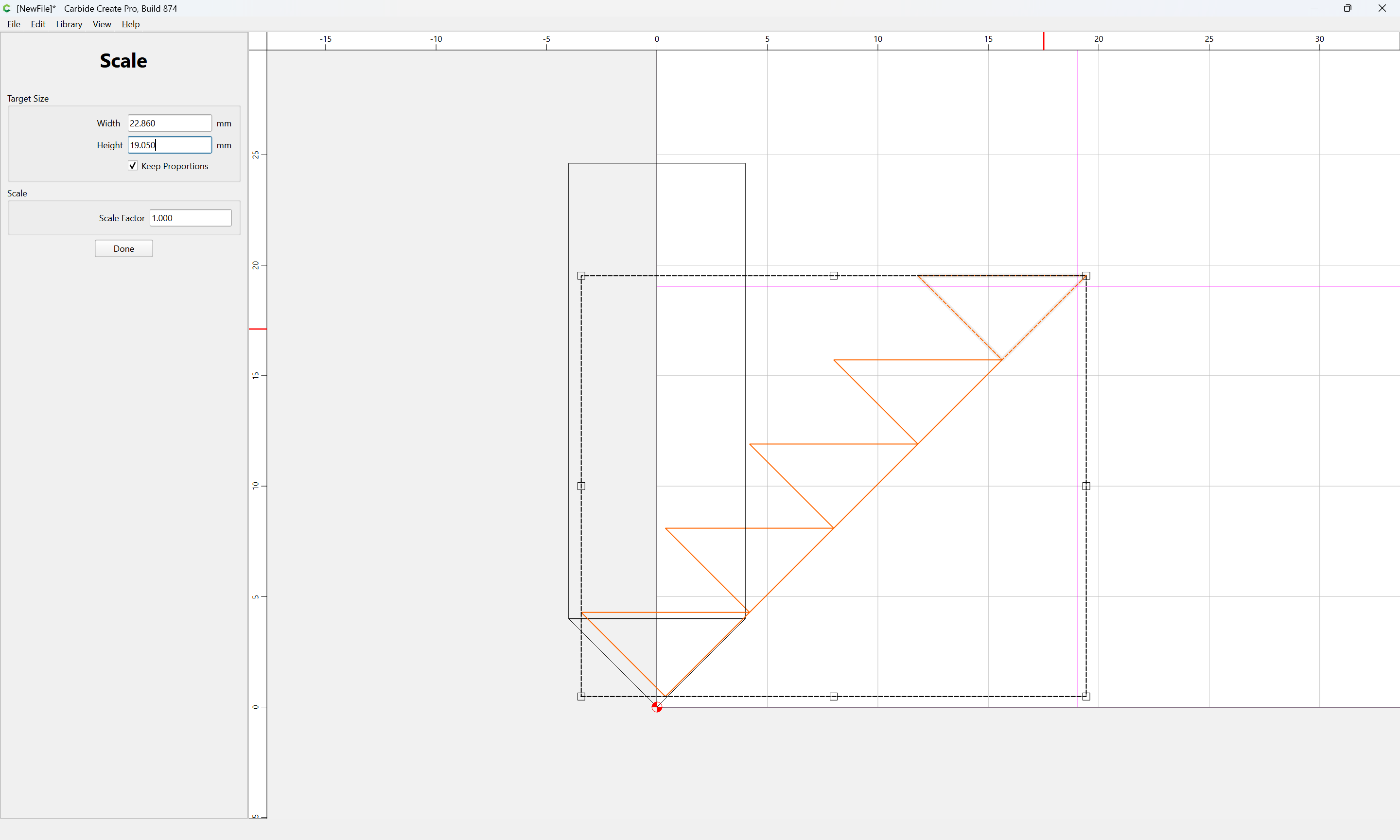
Done
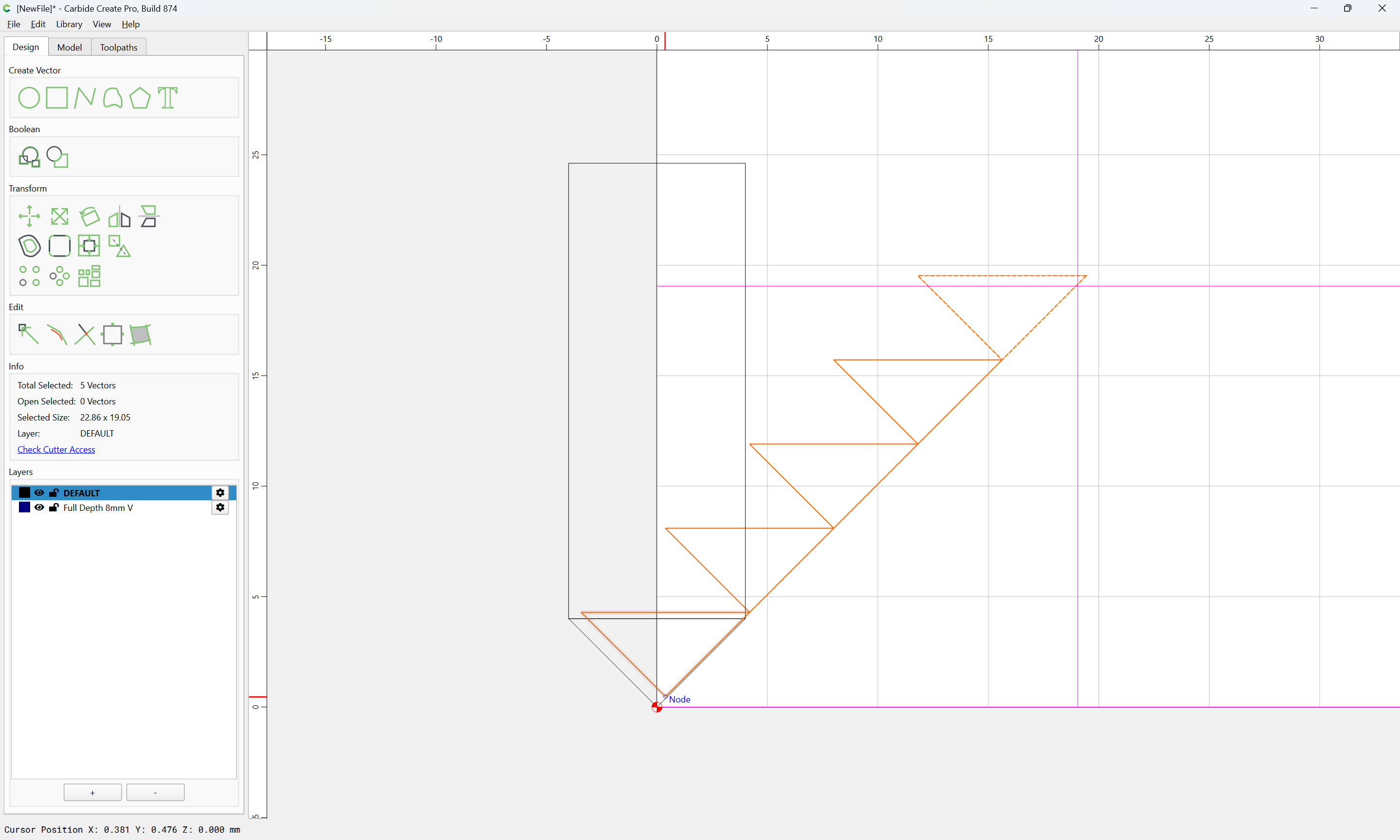
and drag them back into registration:
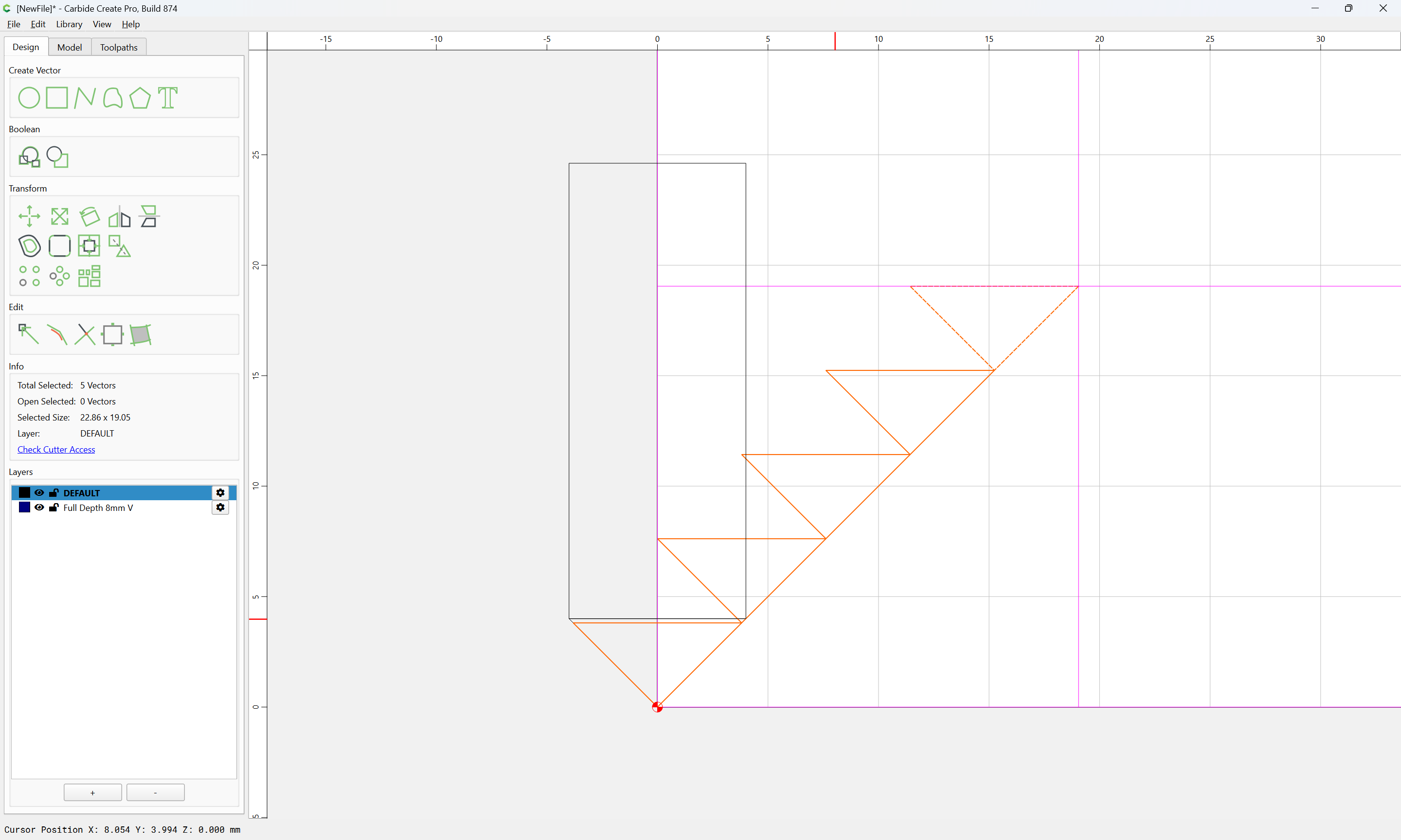
We then draw a line which is as long as the thickness of the stock plus the 8mm width of the tool which will be used to cut the hidden box joints:
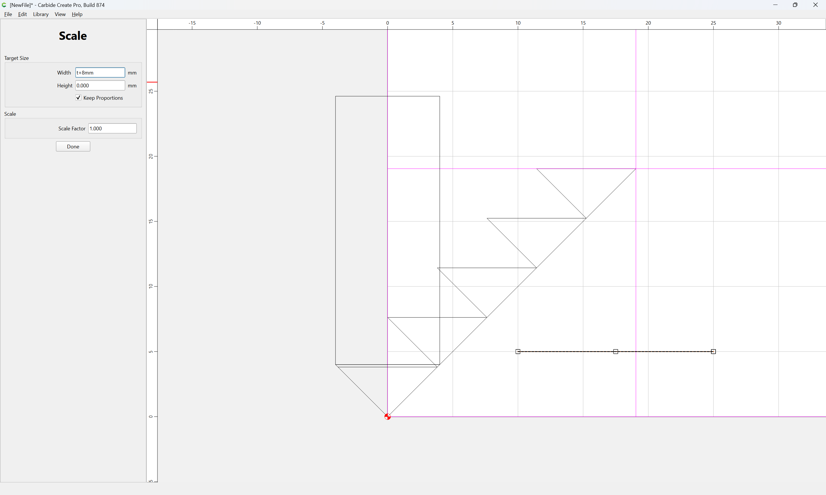
Done
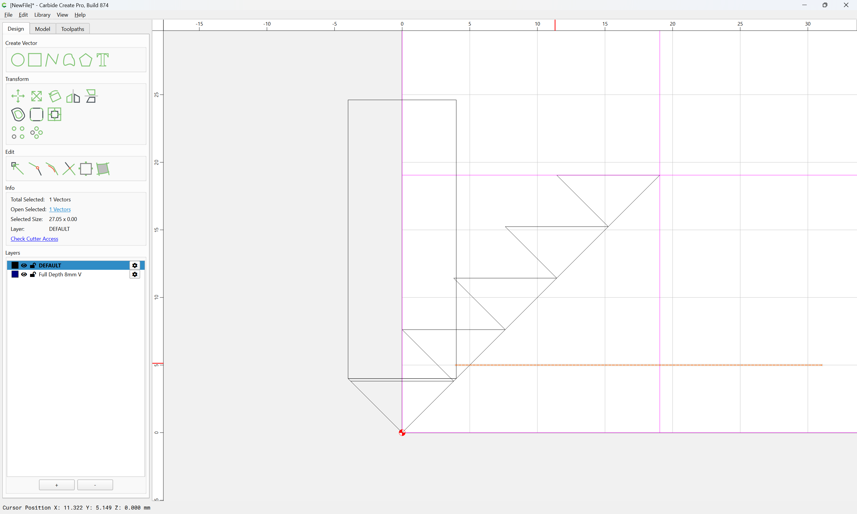
and drag it into registration:
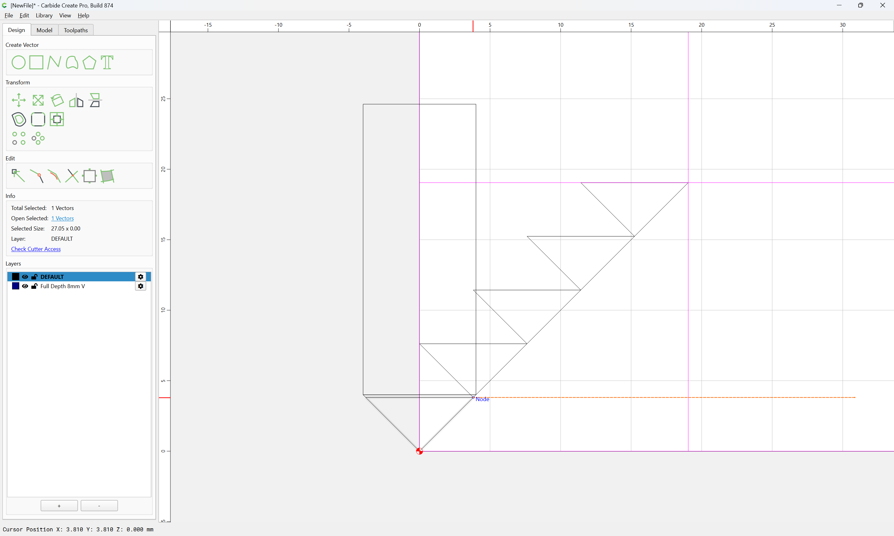
and then replicate it for each V-tool proxy:
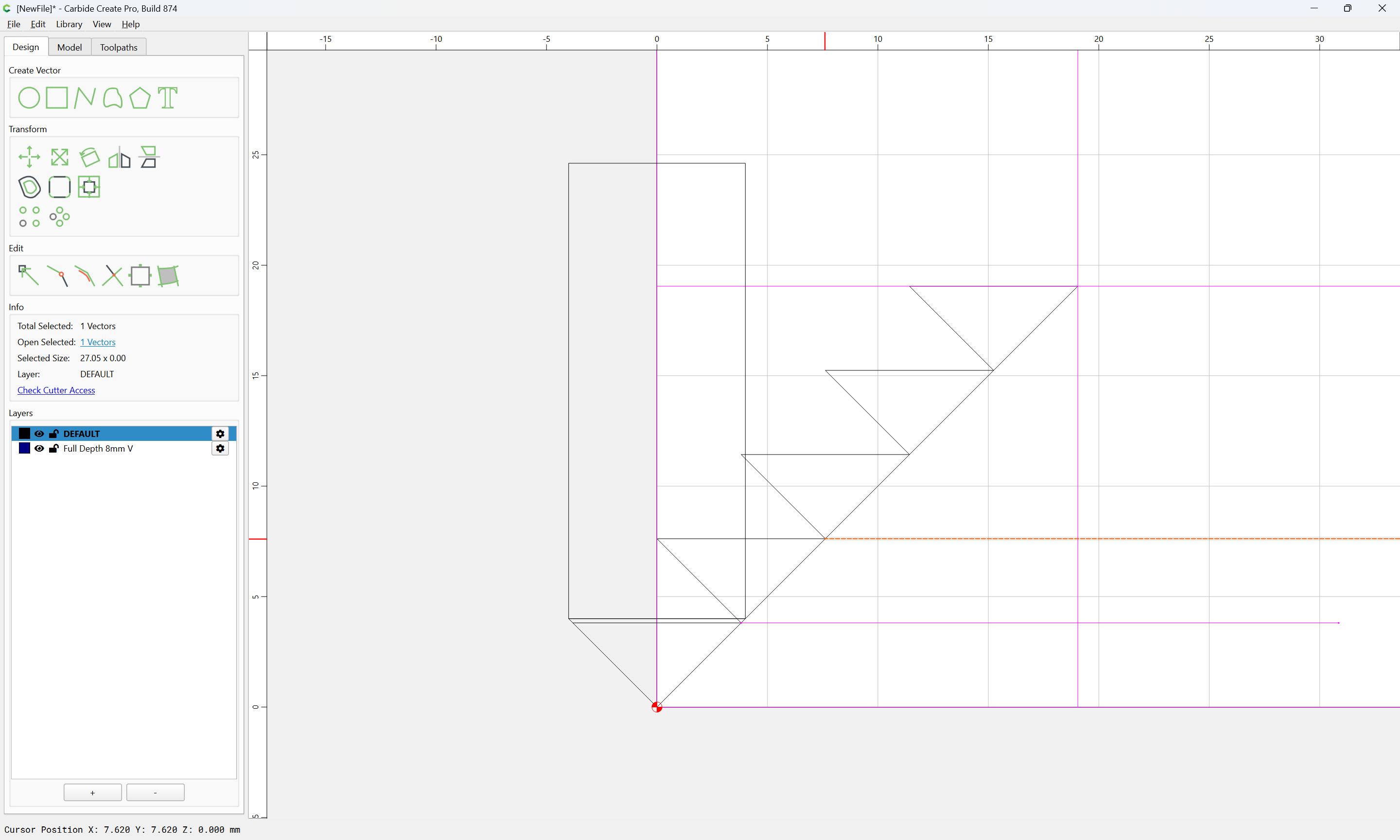
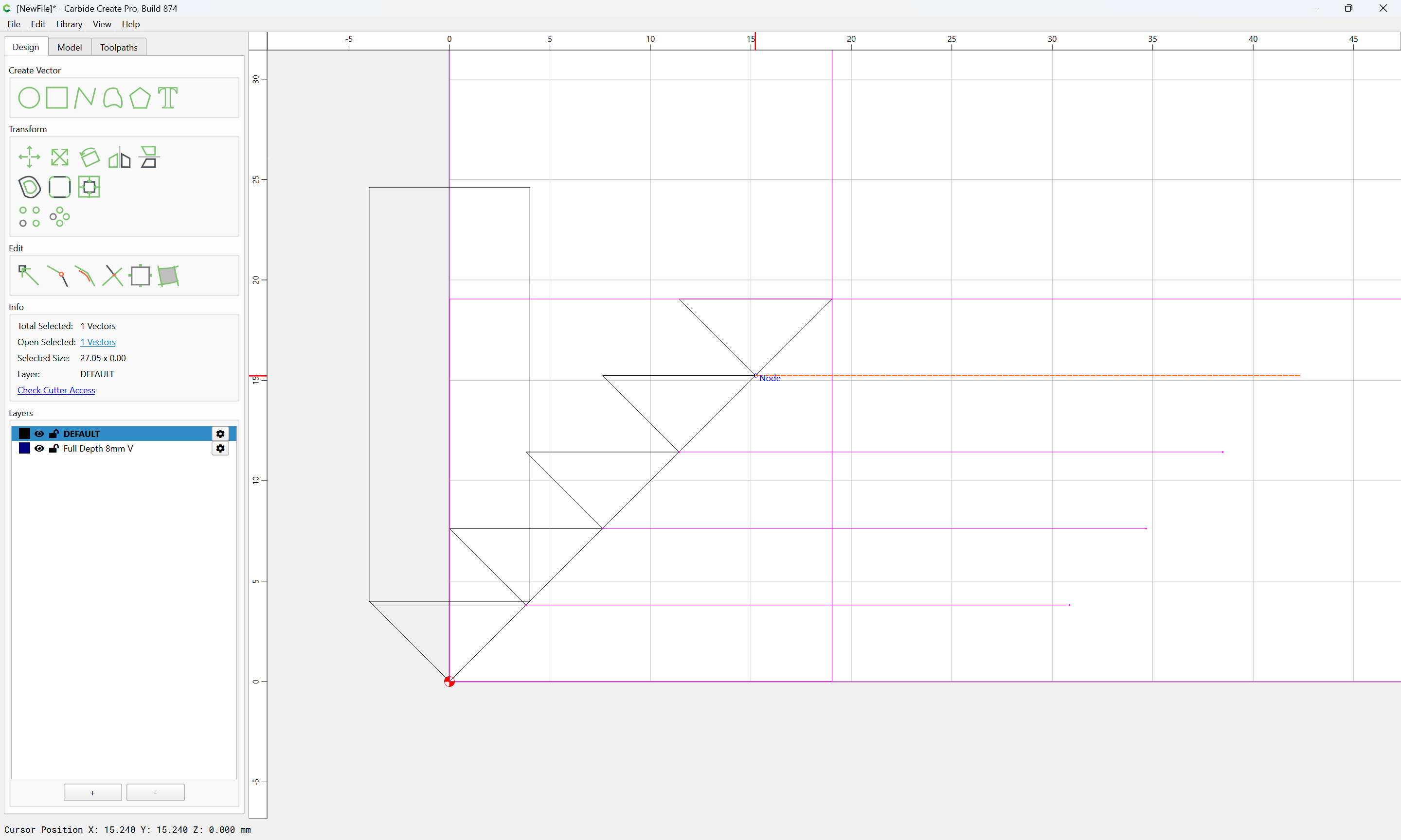
and we make a separate Layer for each depth of cut:
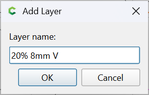
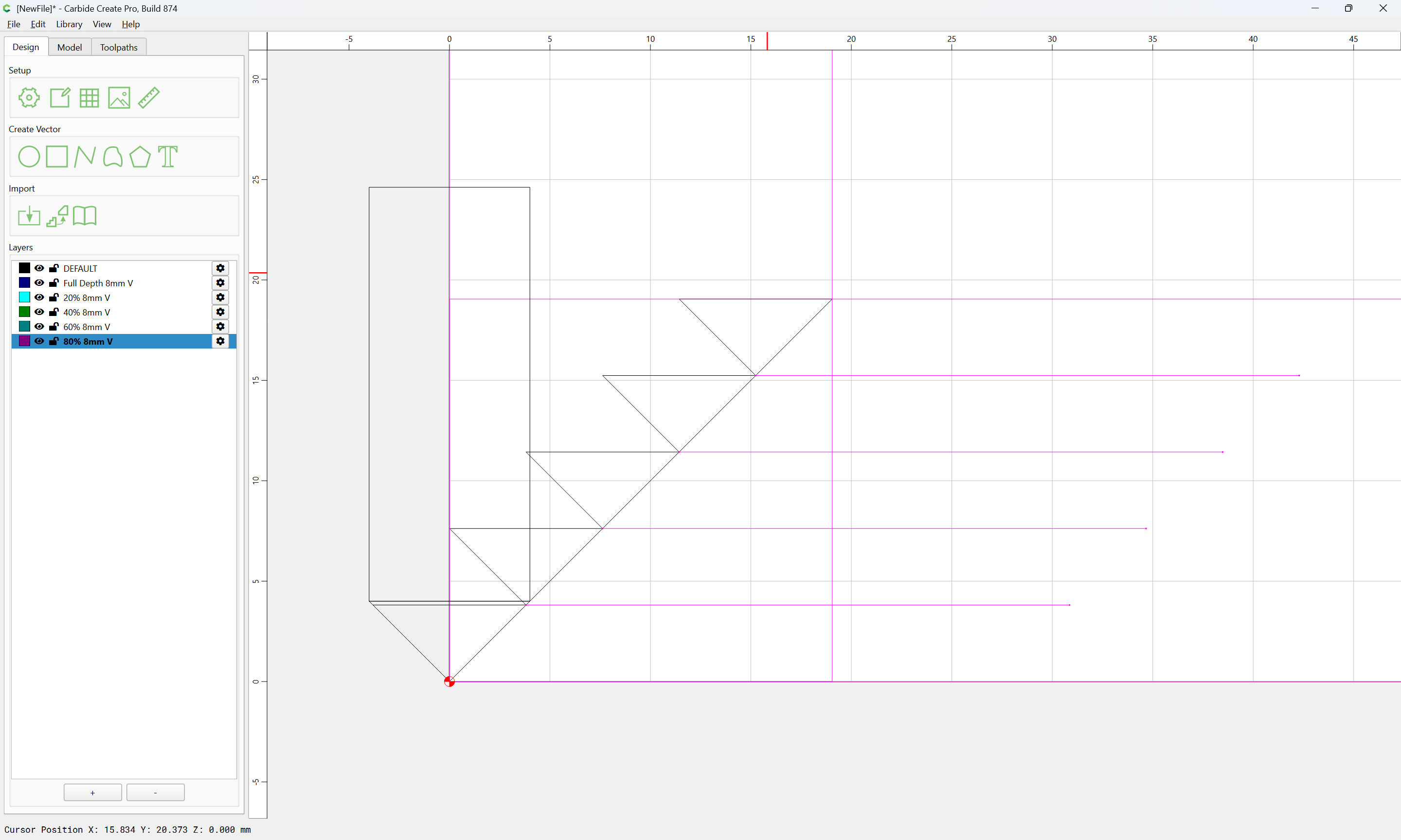
Then at each corner, a set of these lines need to be arranged:
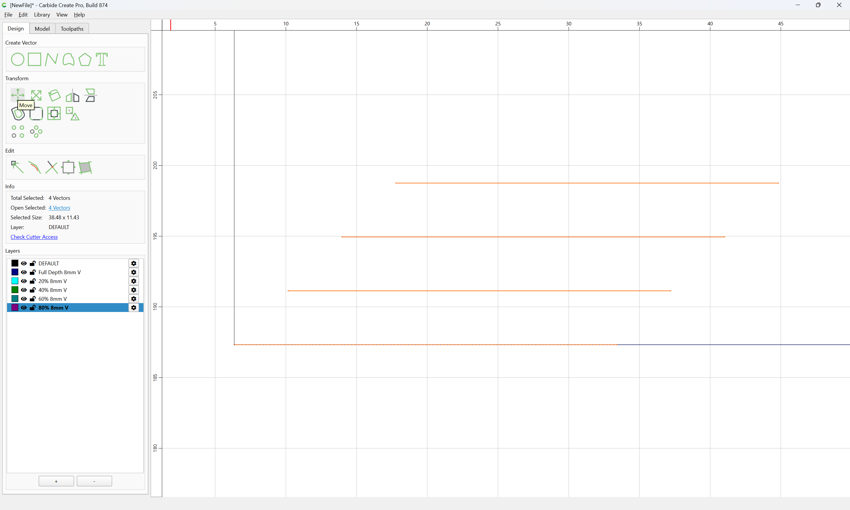
and positioned:
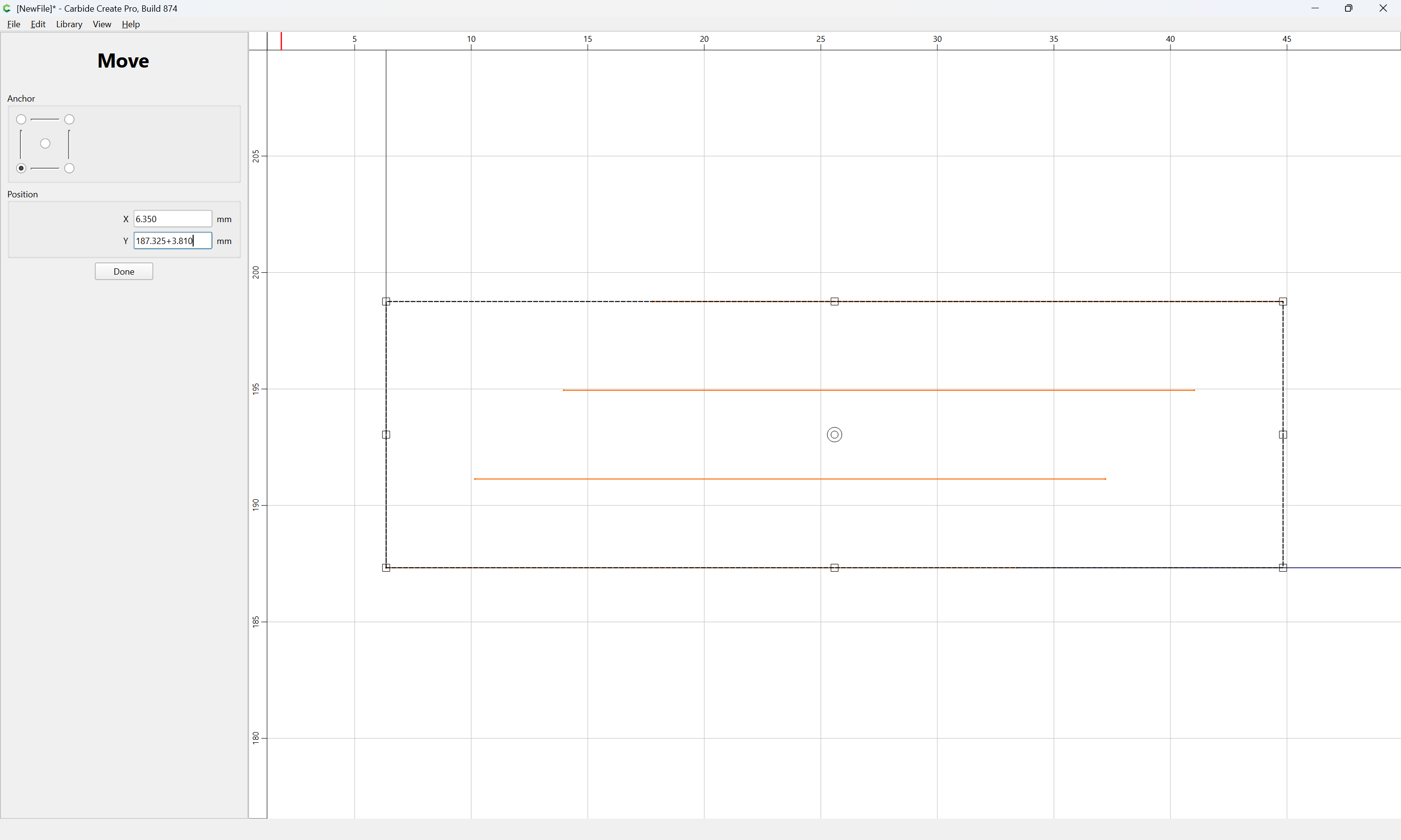
Done
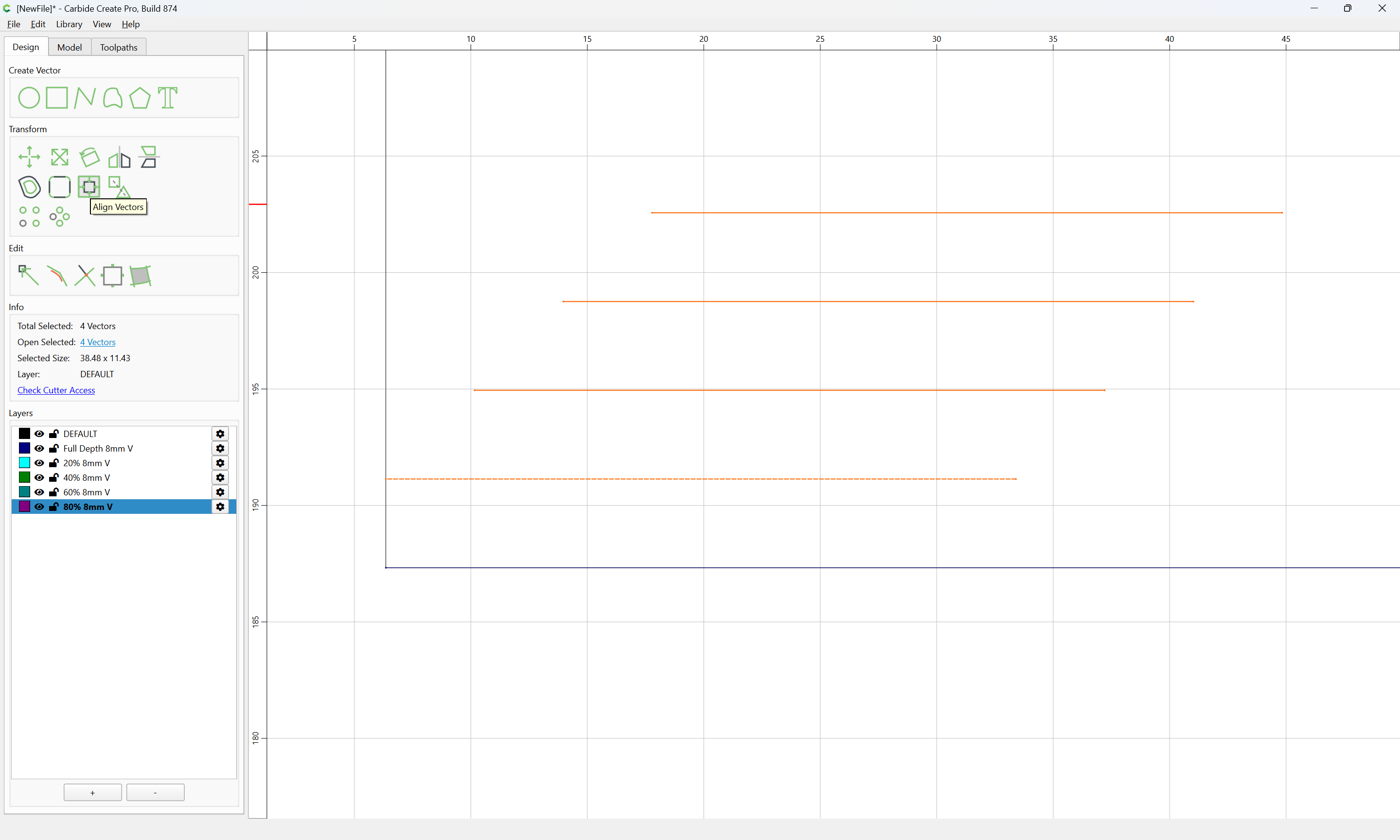
and aligned
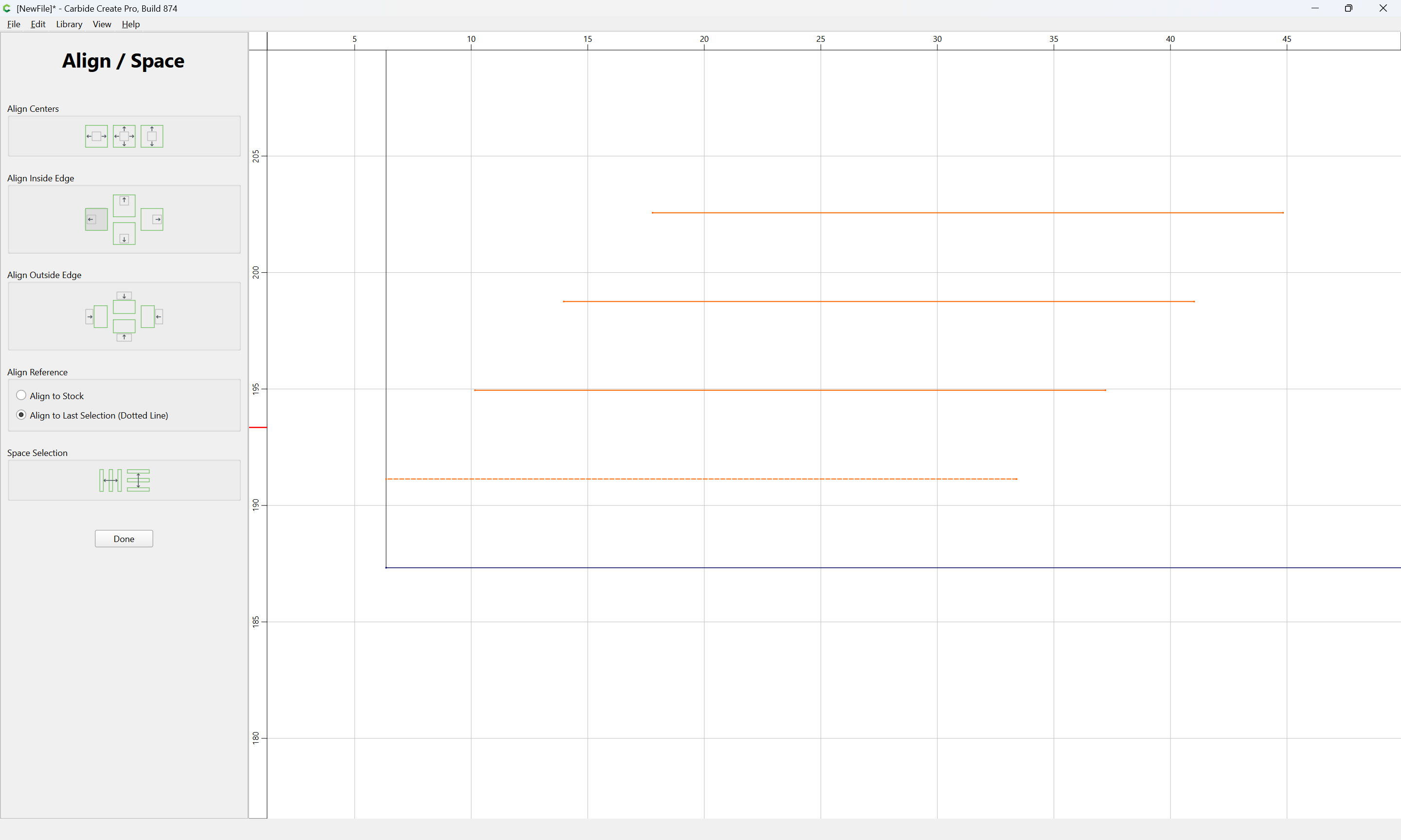
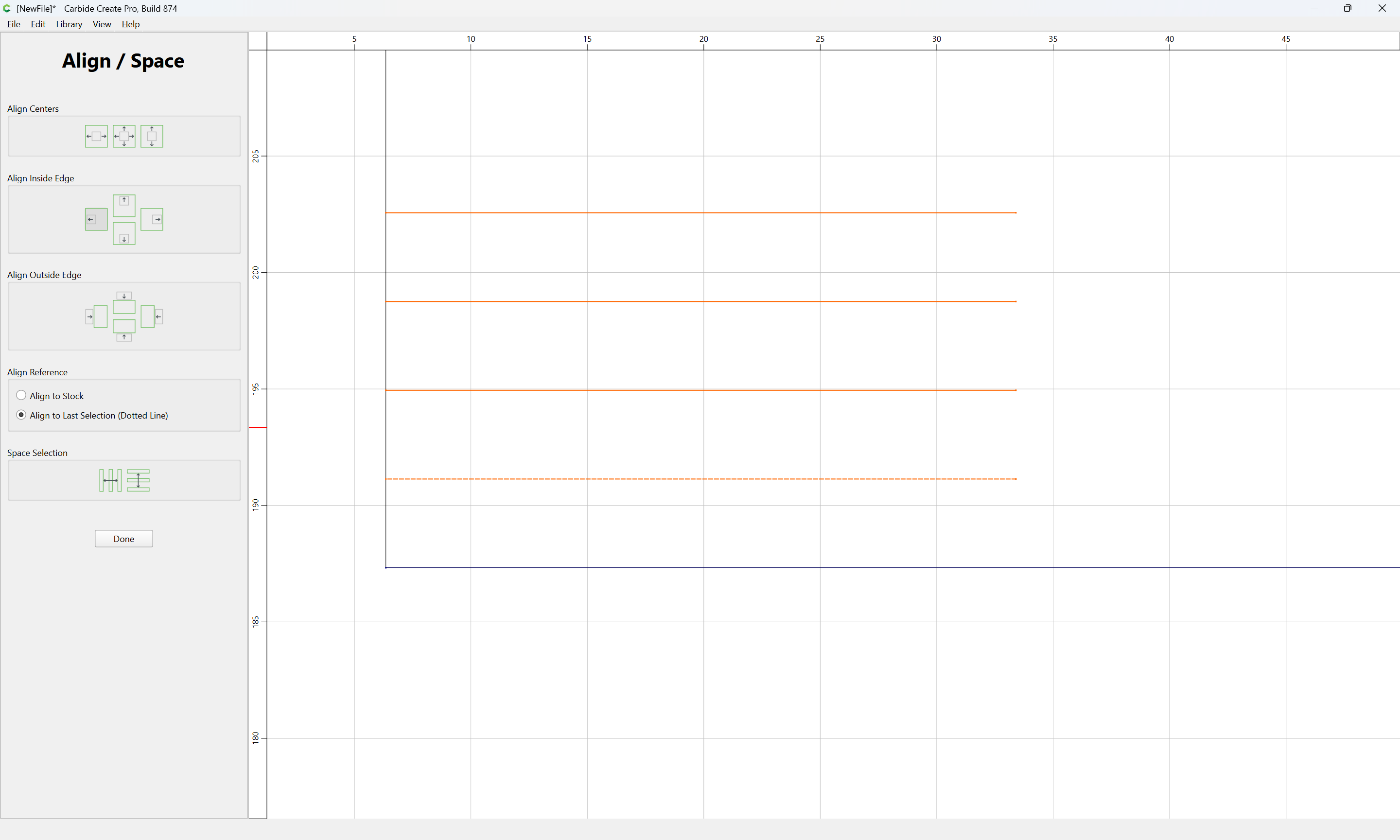
Done

and then each assigned to the appropriate layer:
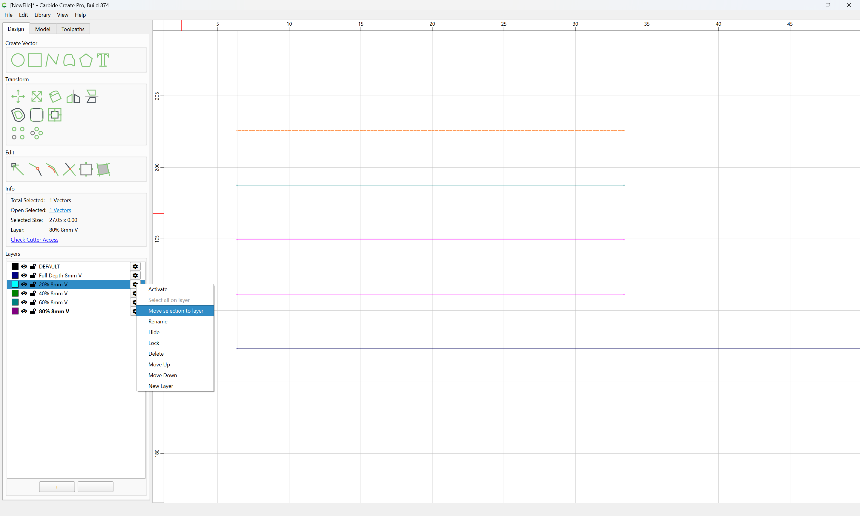
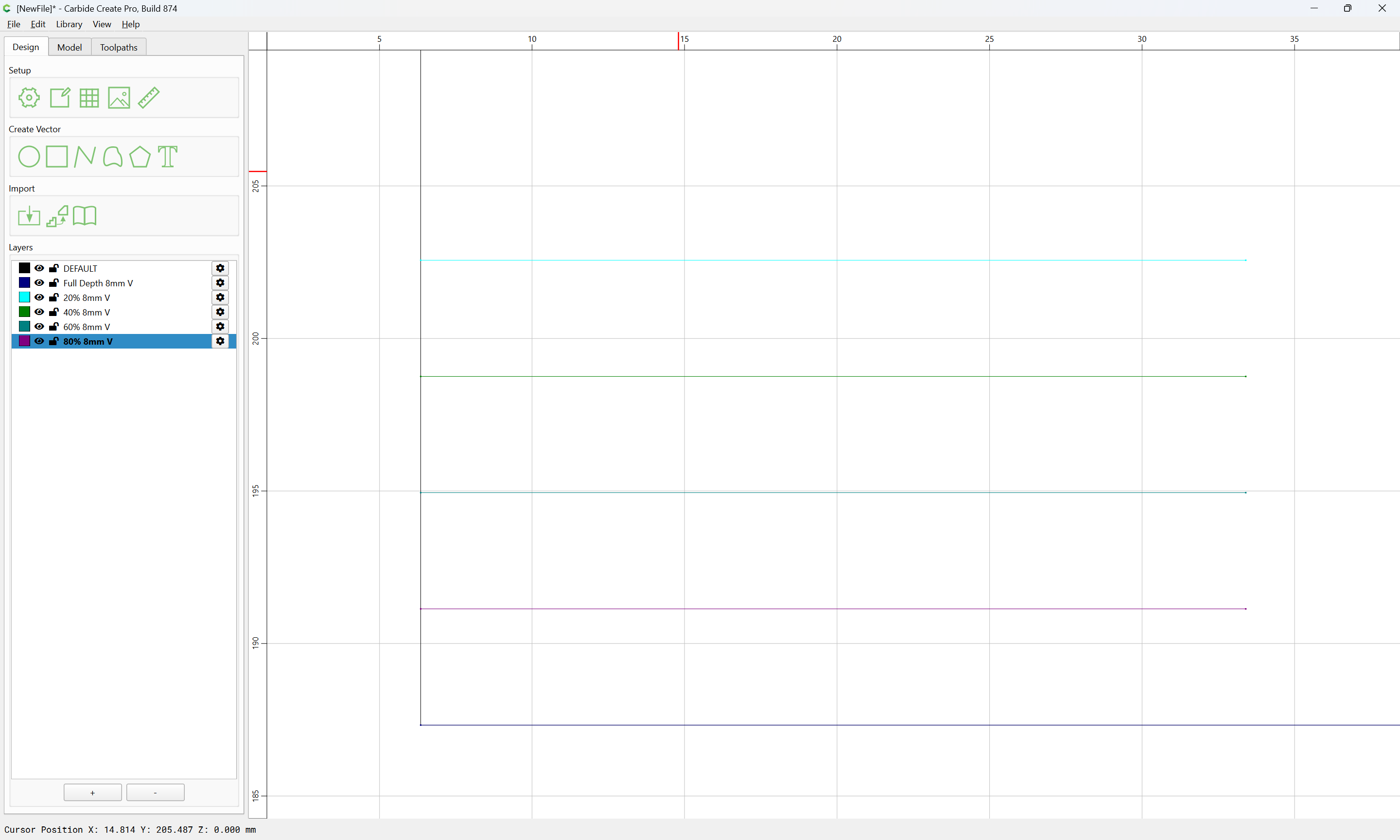
and an appropriate toolpath set up for each layer:
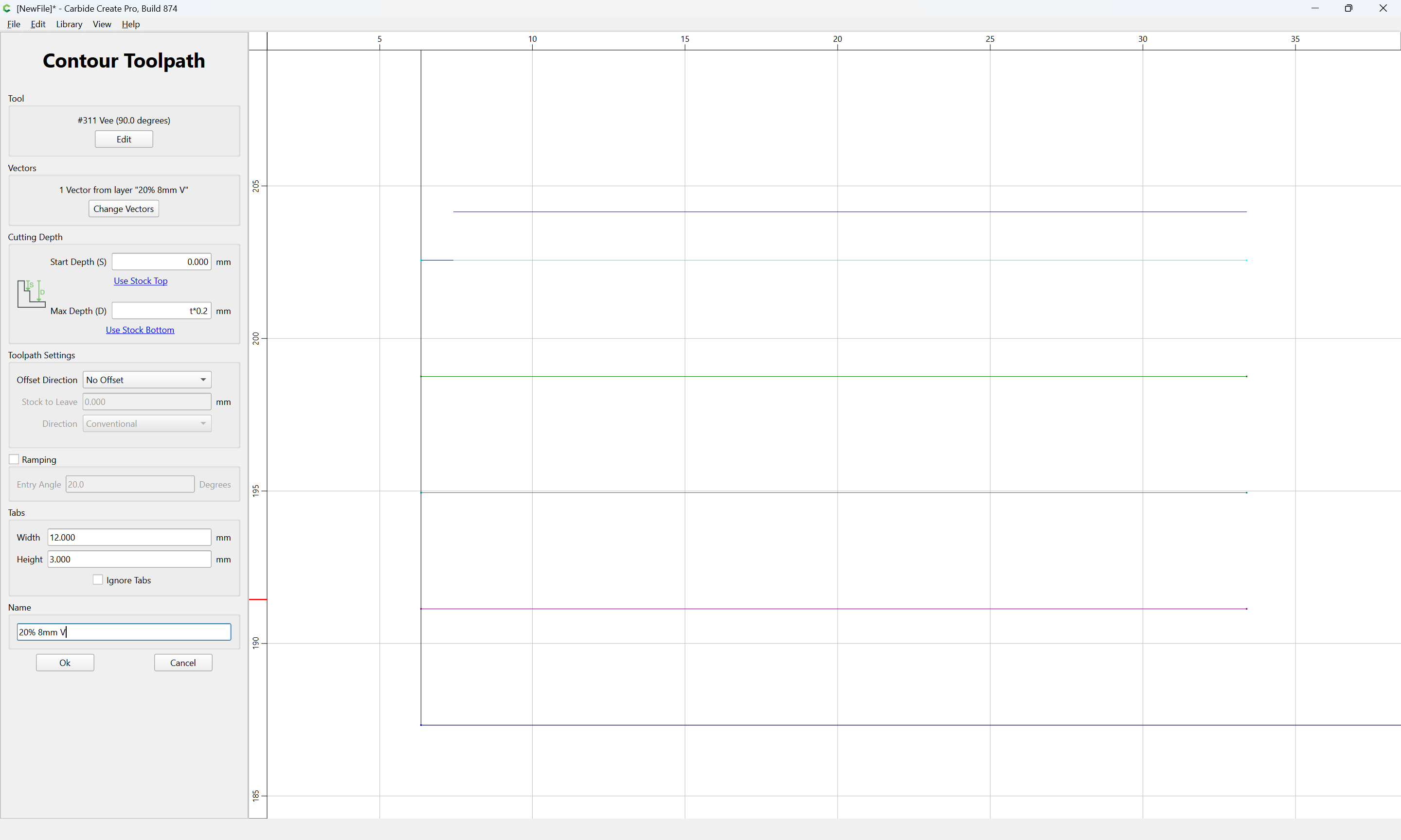
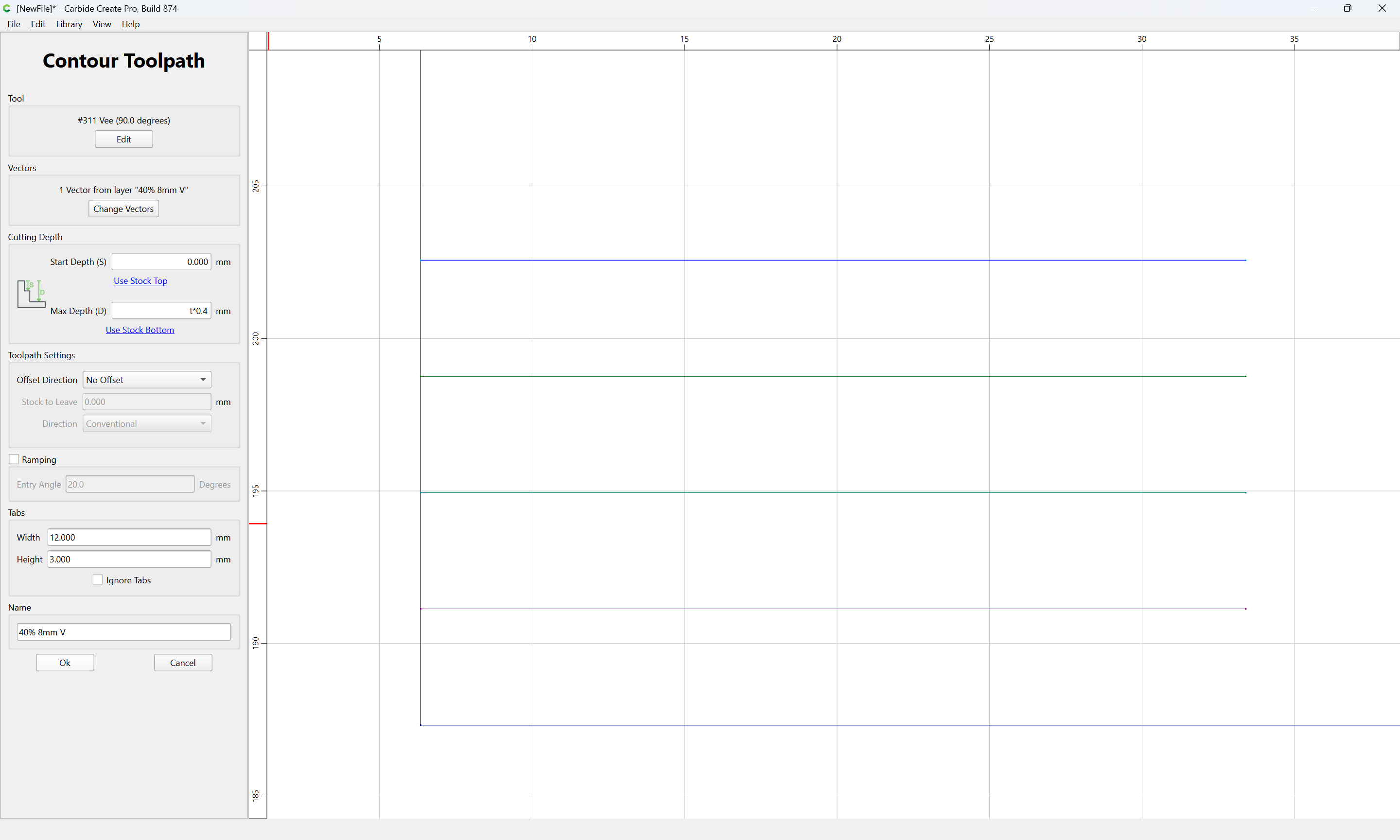
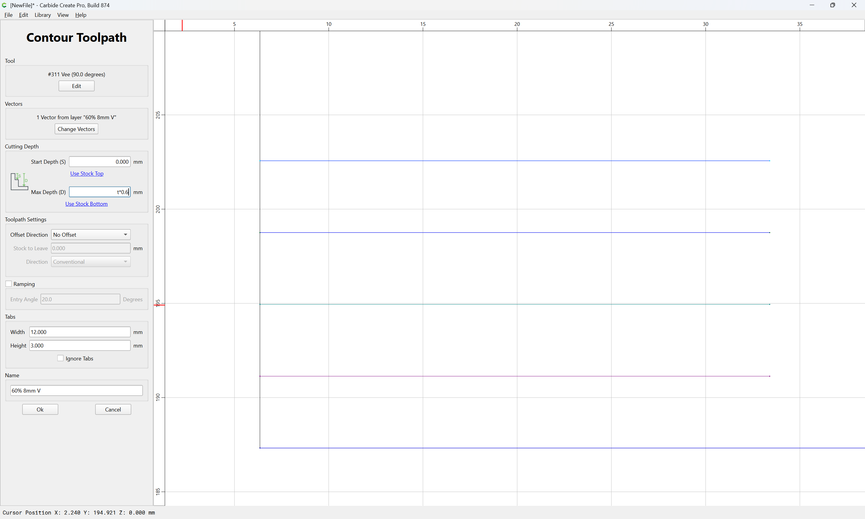
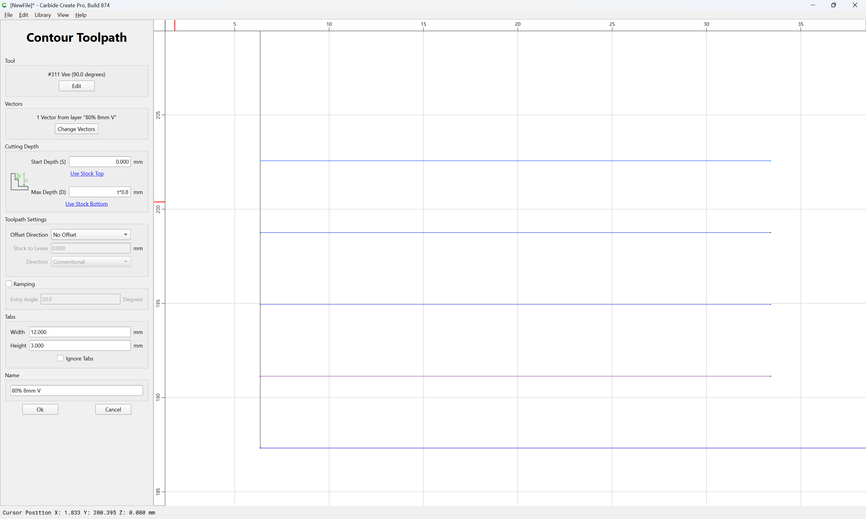
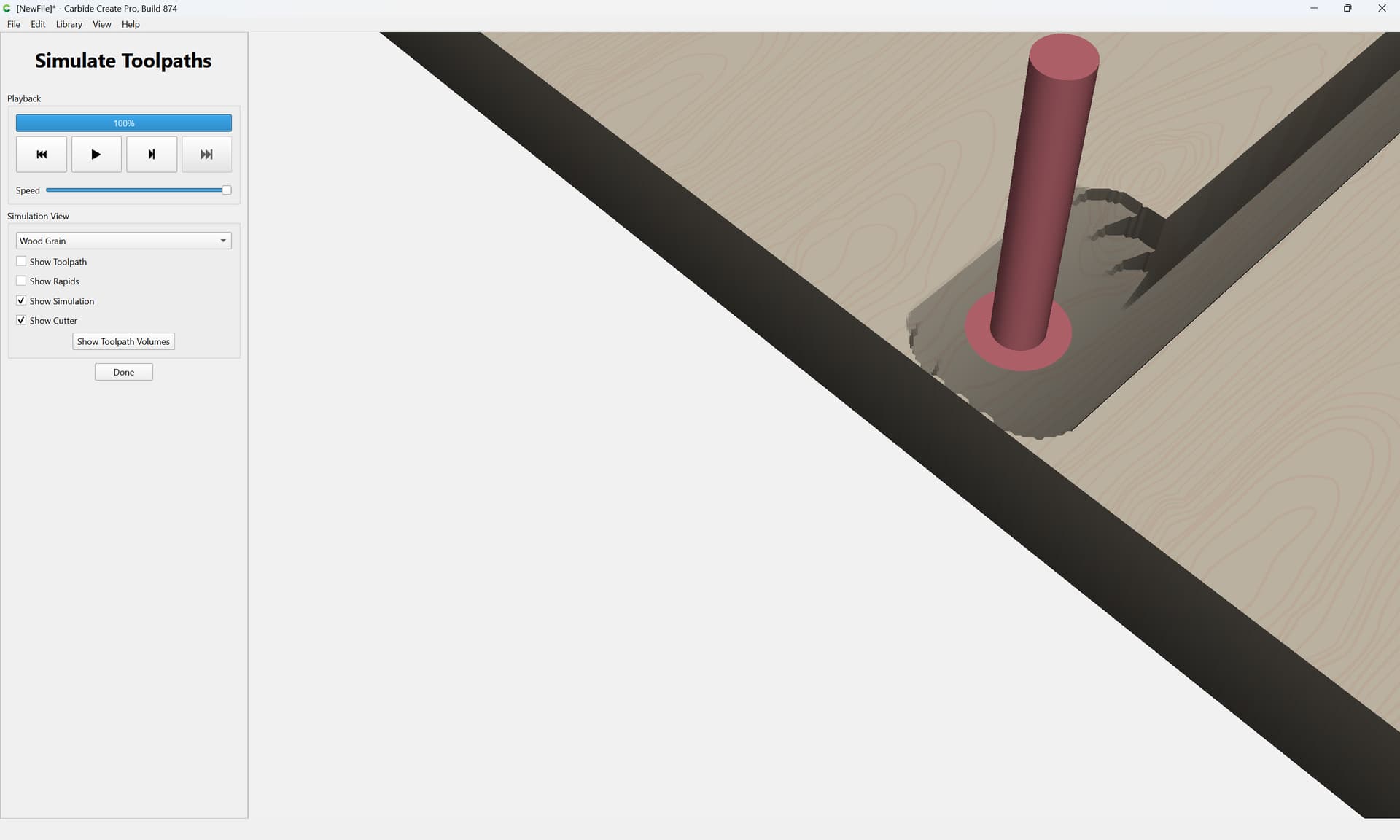
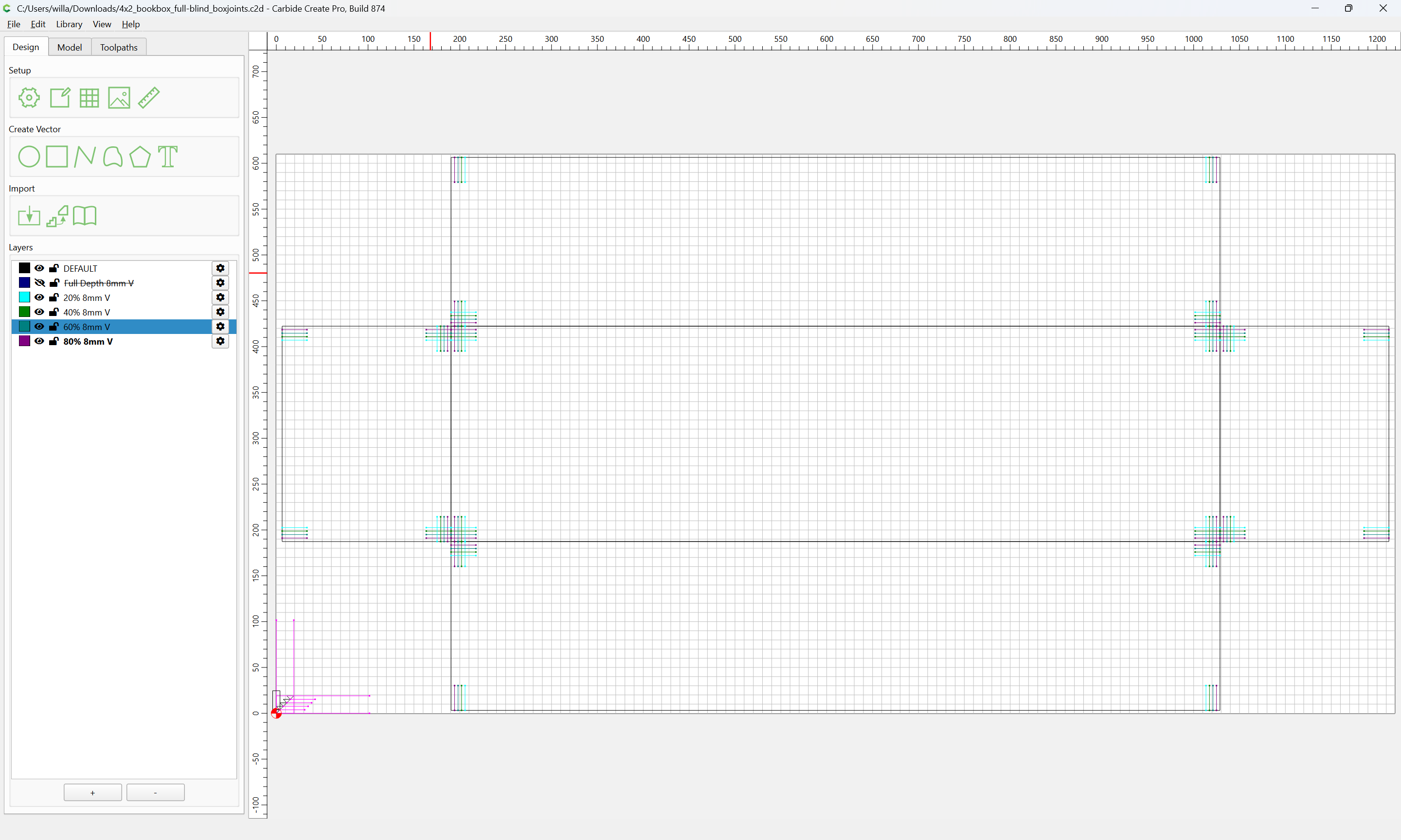
Duplicate to each corner:
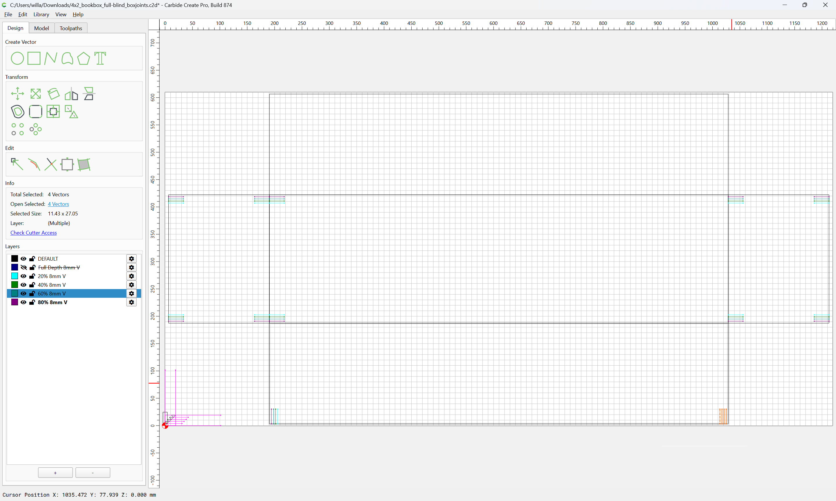
rotating as necessary.
For the corners, select the geometry:
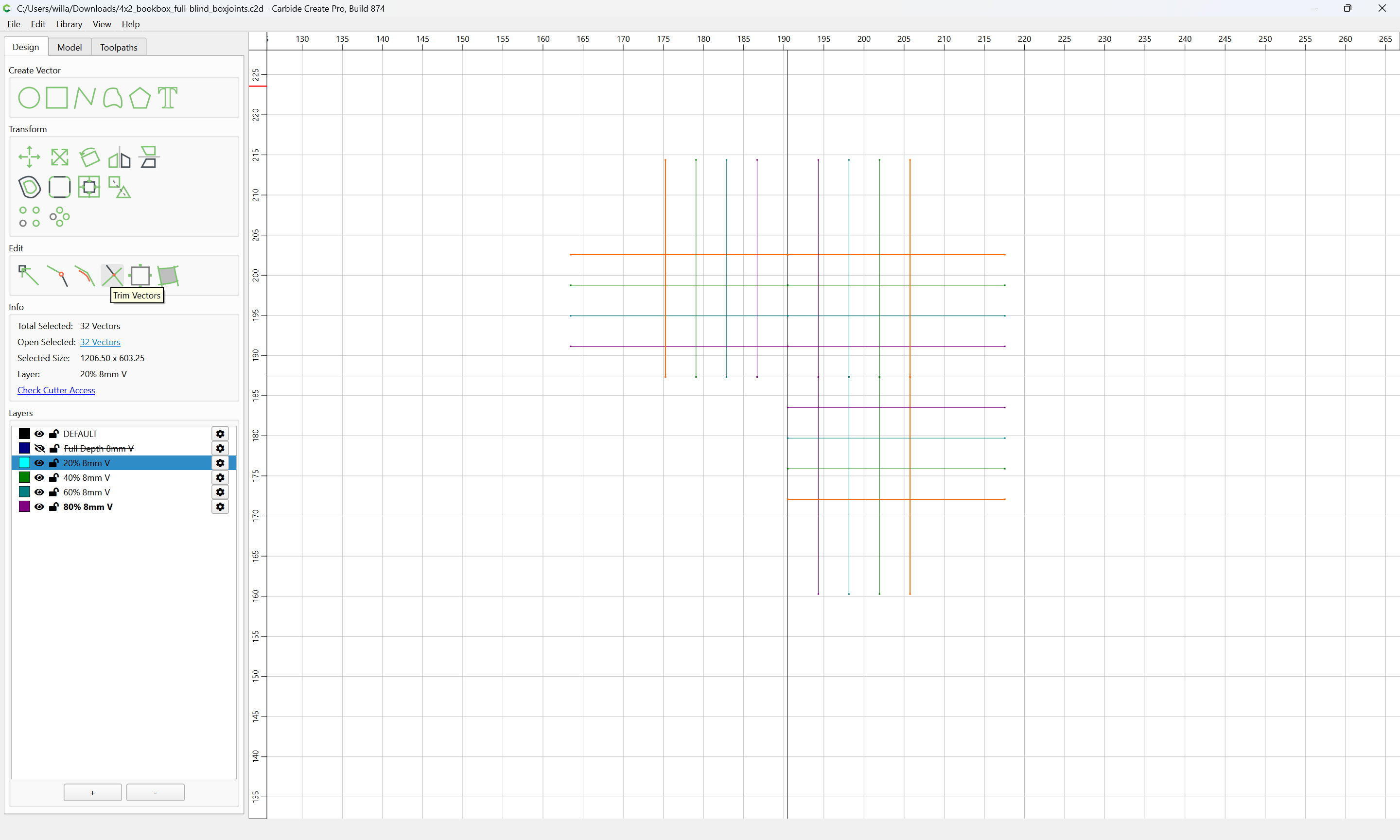
and use Trim Vectors:
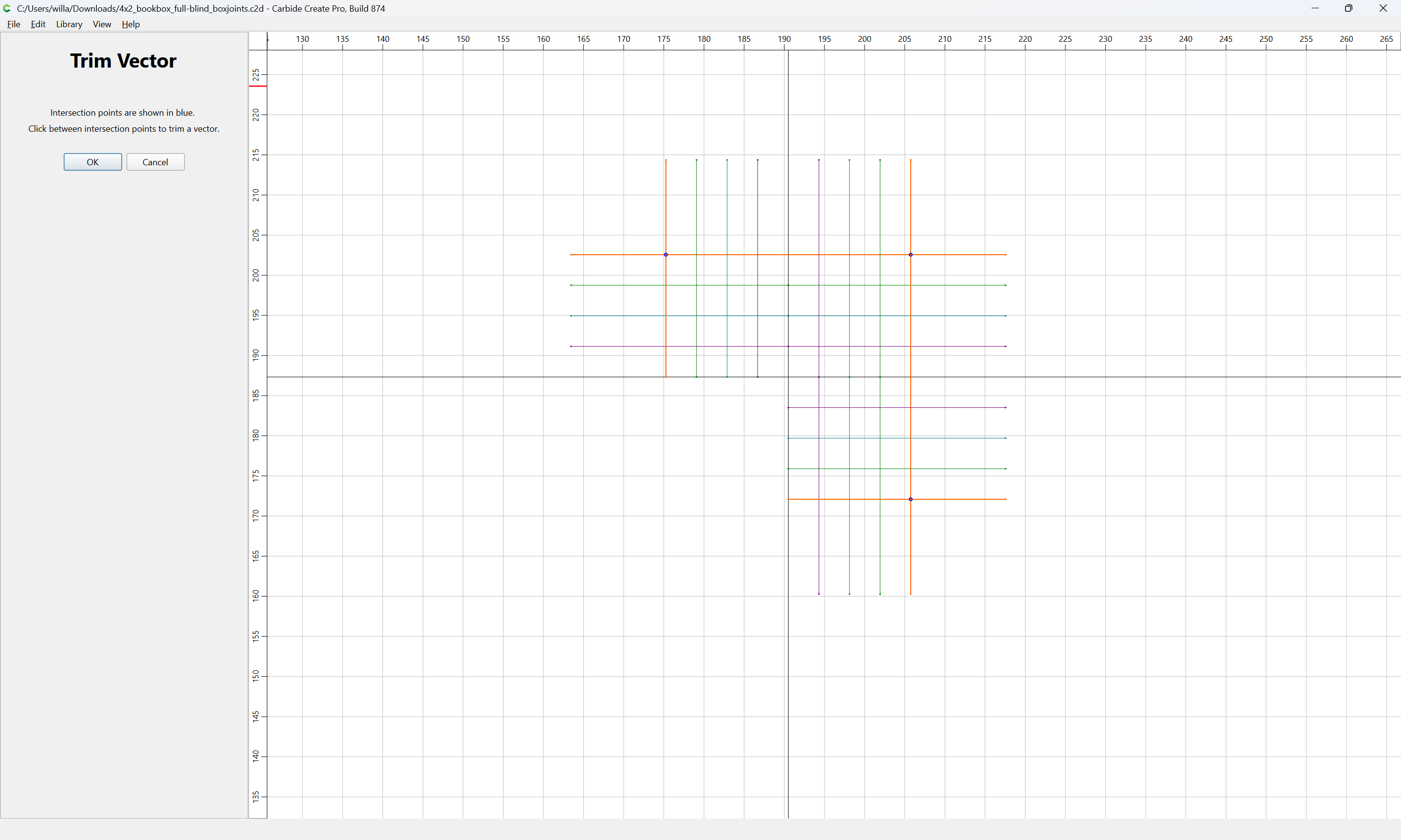
to remove what is redundant:
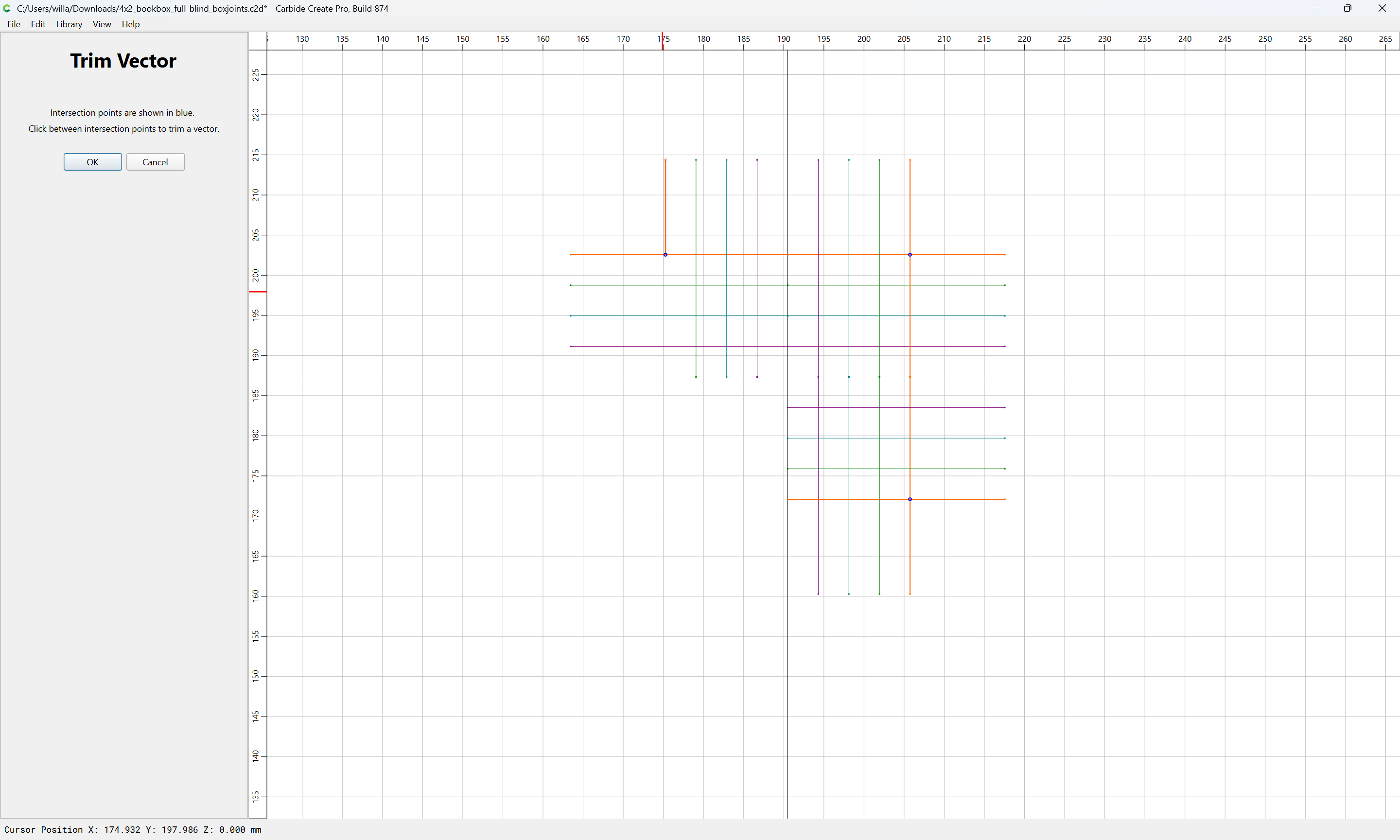
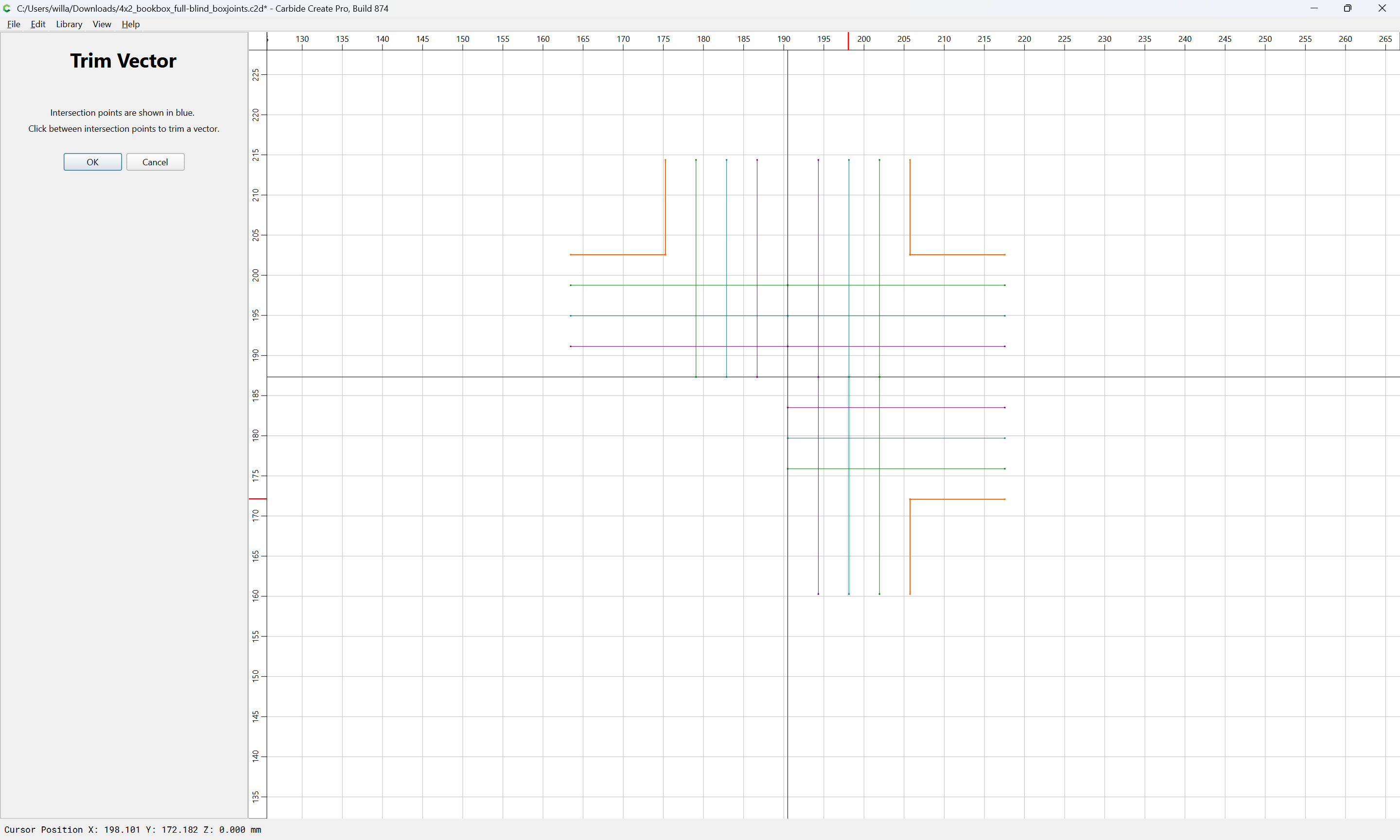
until one arrives at:
OK
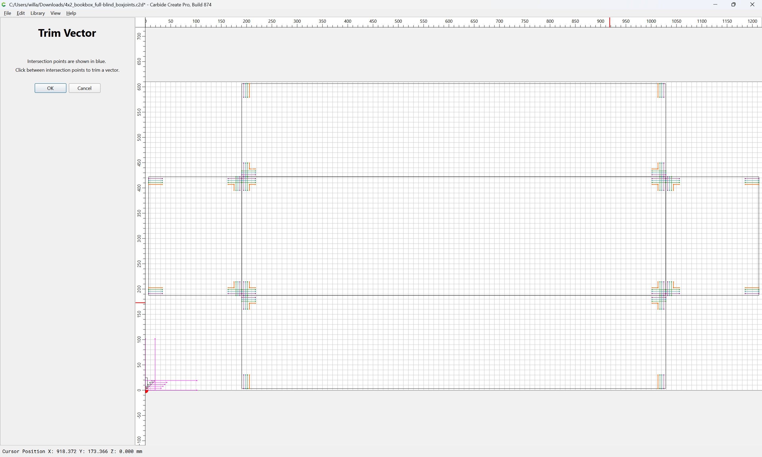
OK
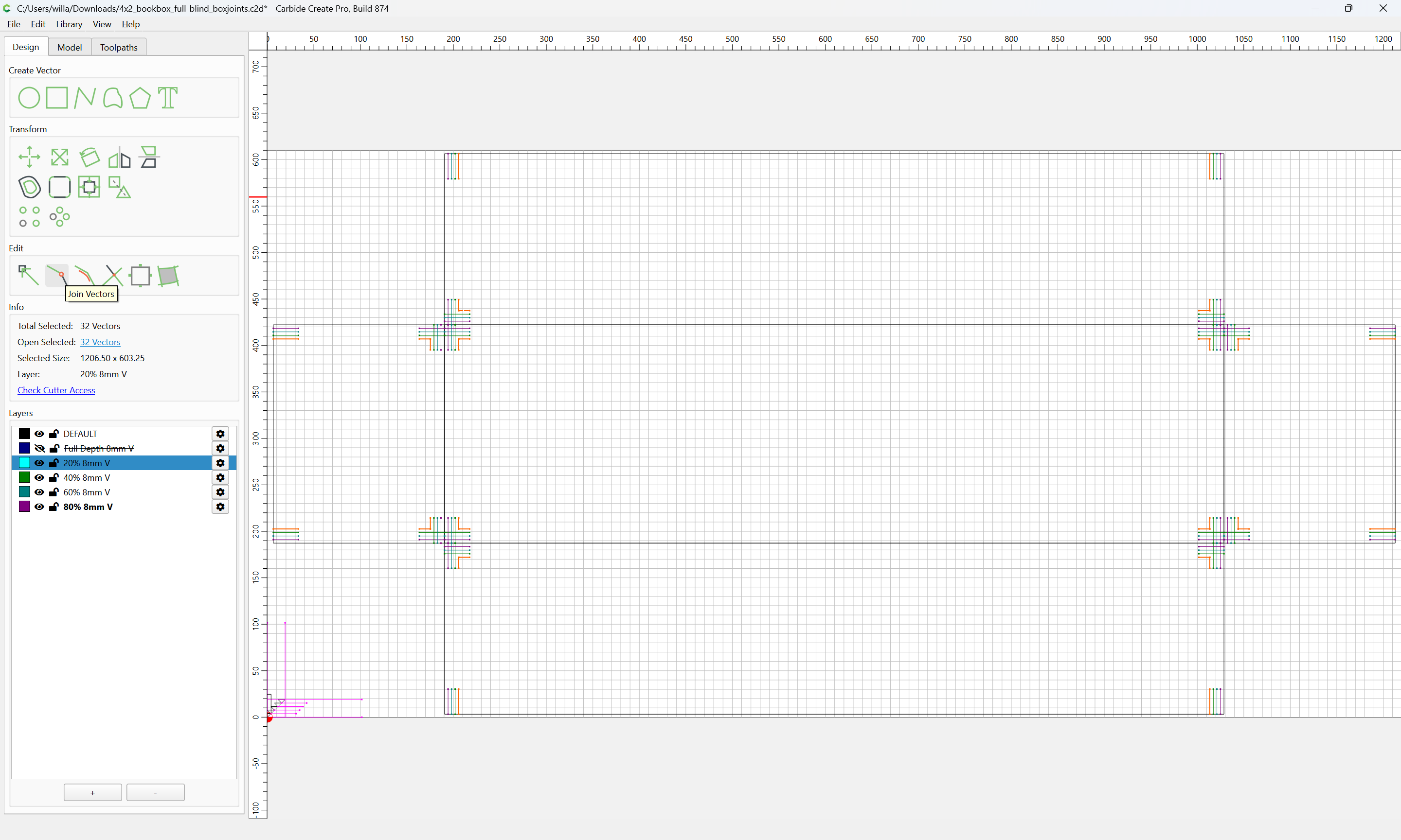
Then use Join Vectors:
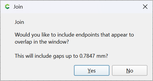
Yes
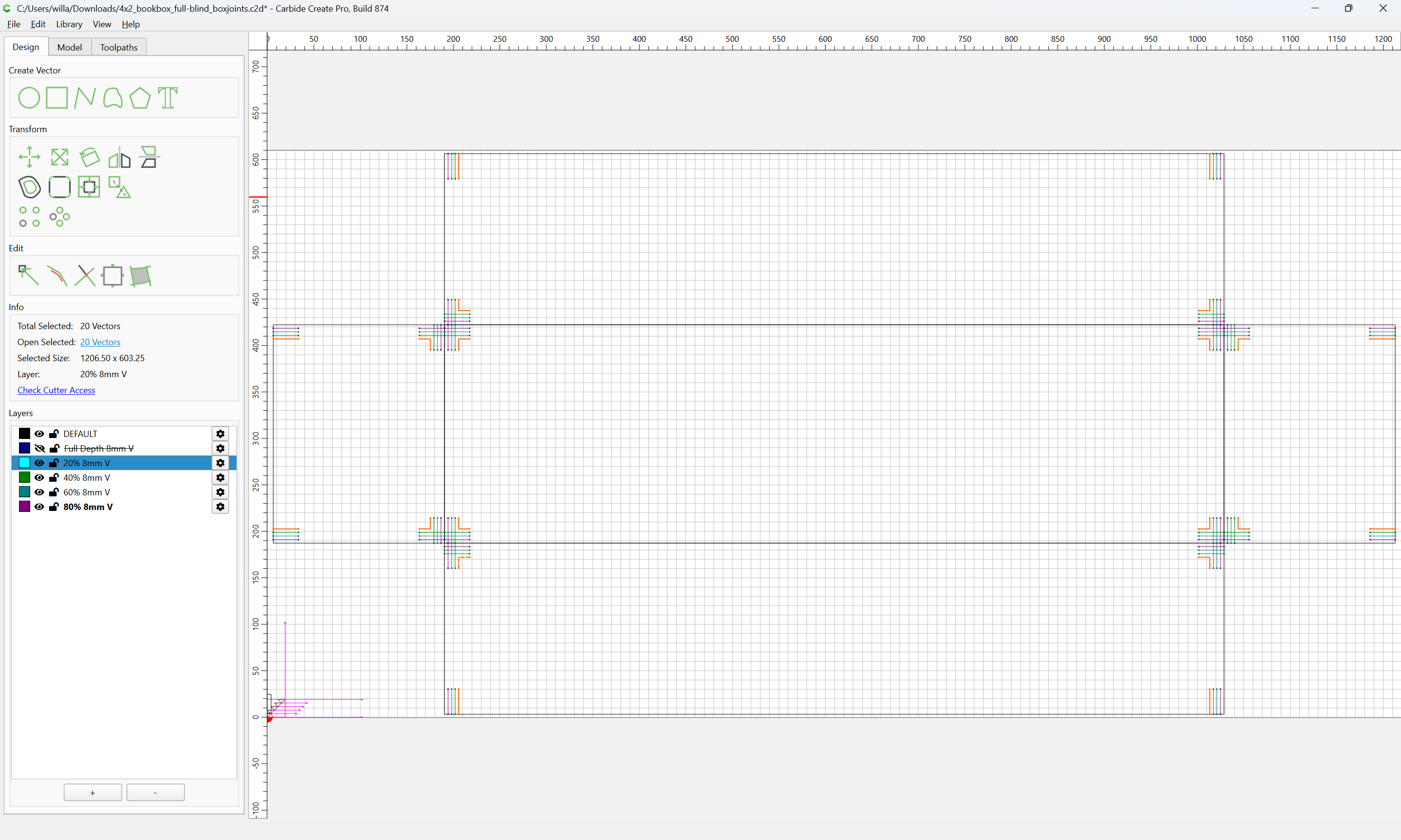
Repeat for the other layers…
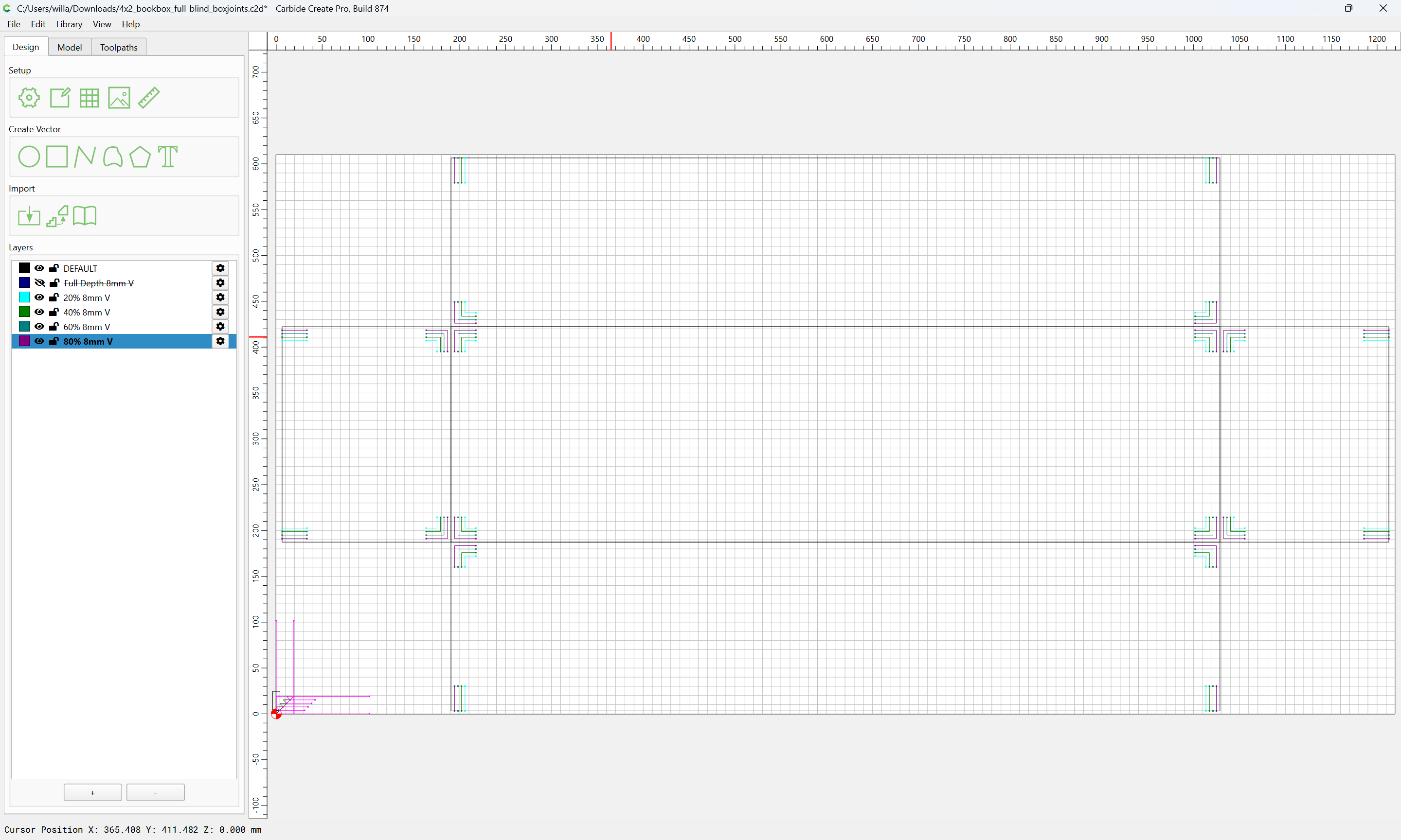
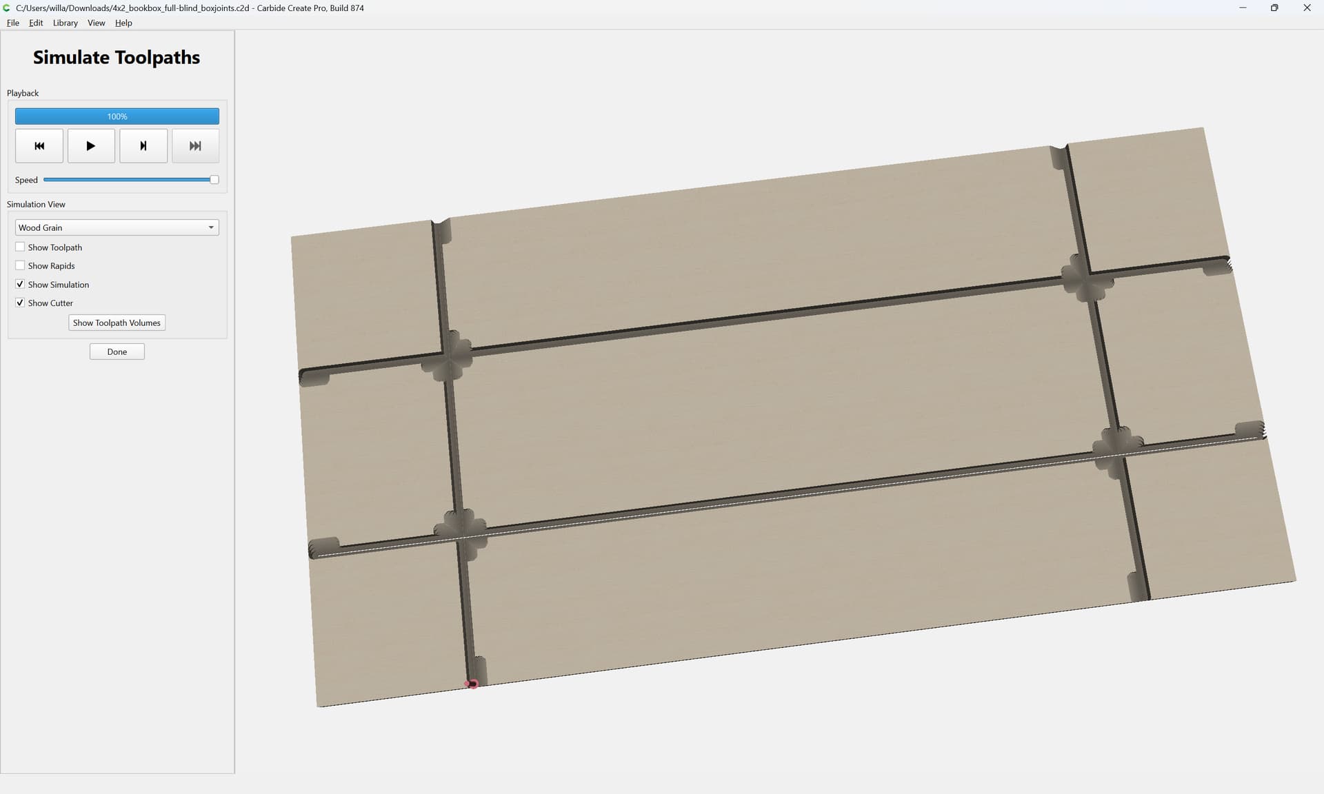
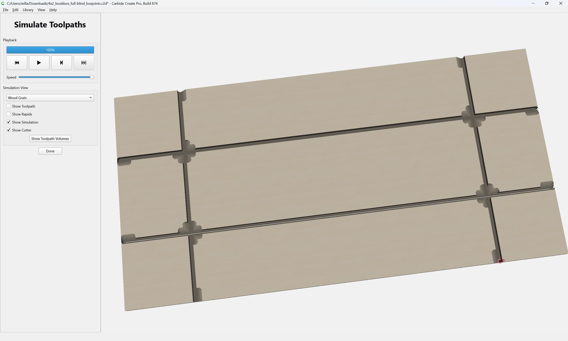
which previews as:
For the uppermost cut it will be necessary to fill in the interstices:
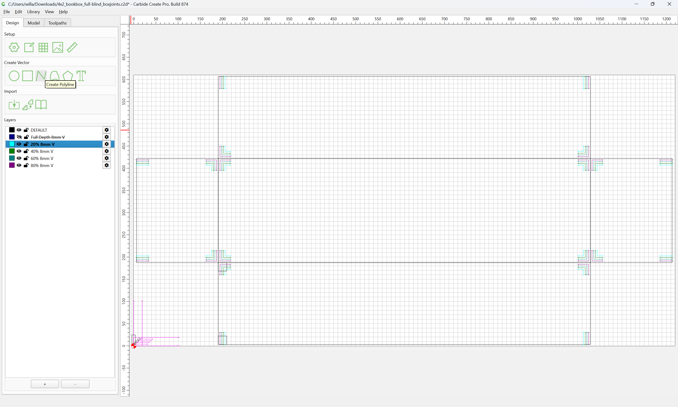
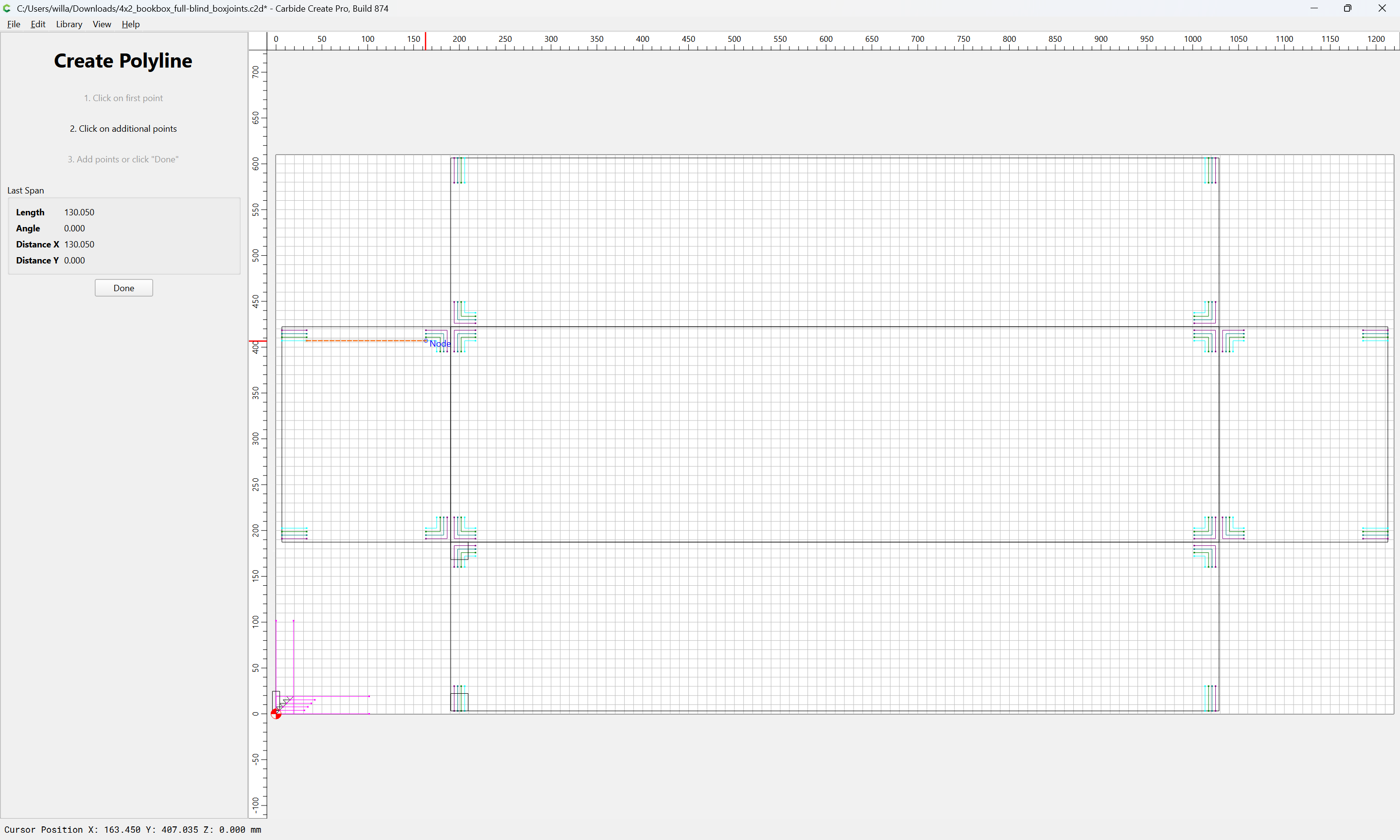
select them all:
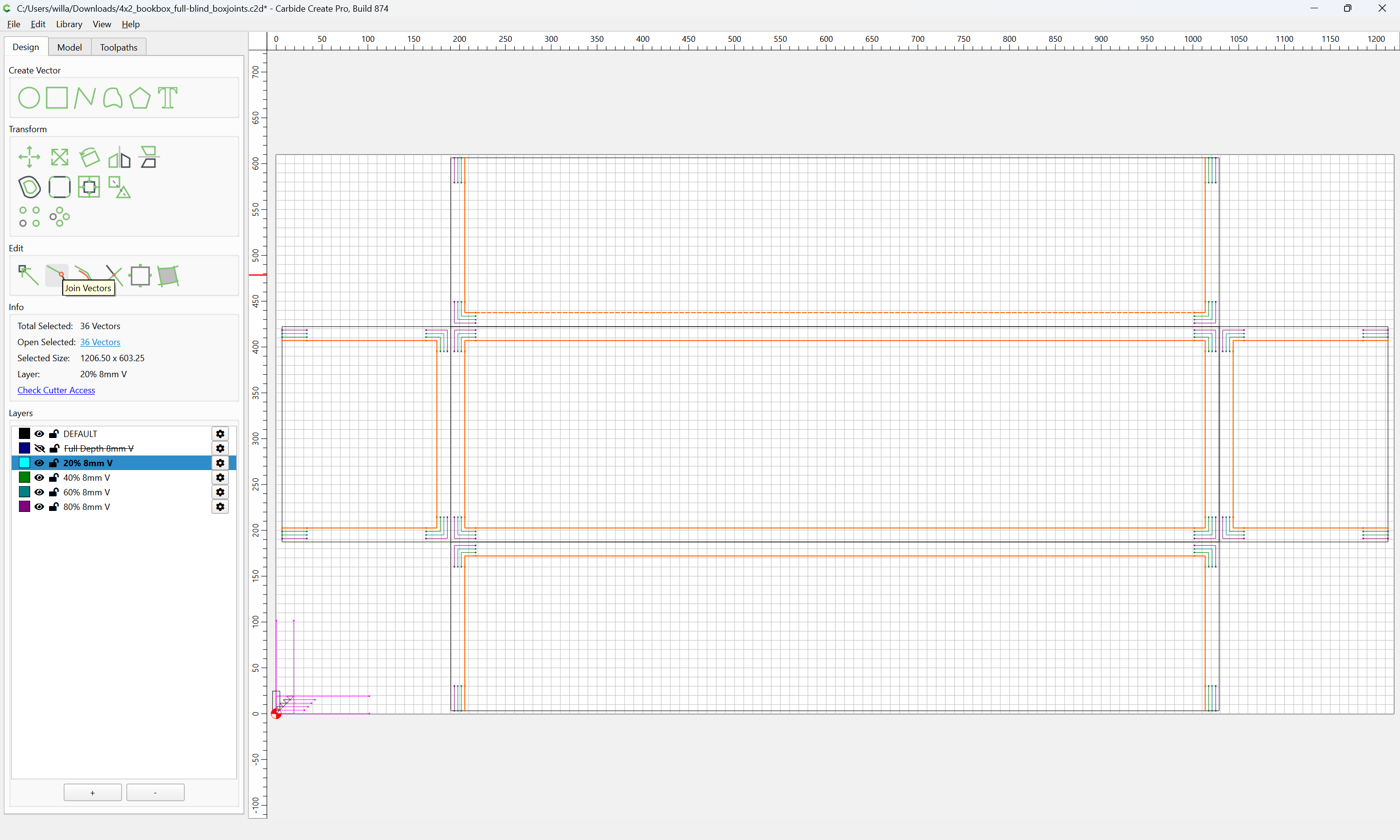
and Join Vectors:
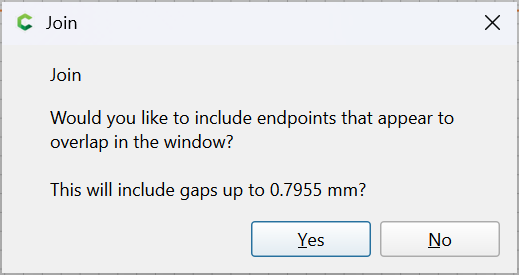
Yes
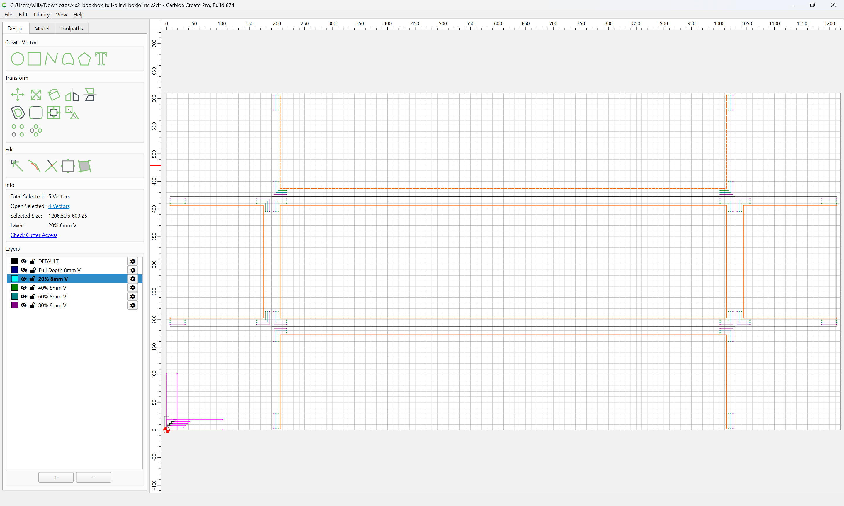
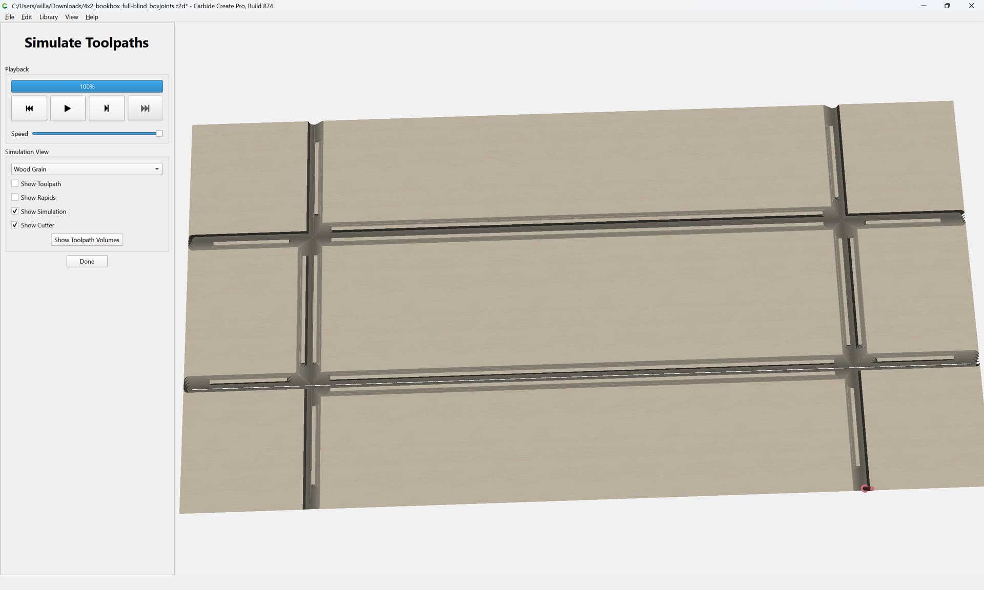
which then previews as:
1 Like
With all the V-tooling geometry defined it will be necessary to turn to the square cuts — three depths will be necessary:
- full-depth at the outside edges of the top/bottoms and sides
- shallow-depth describing the edges of the top-most V-tooling cut
- depths to the pocket depth (penultimate V-tool cut depth)
The easiest to set up is the full-depth which is an outside contour cut along the outside edges — as before, we set up a Layer:
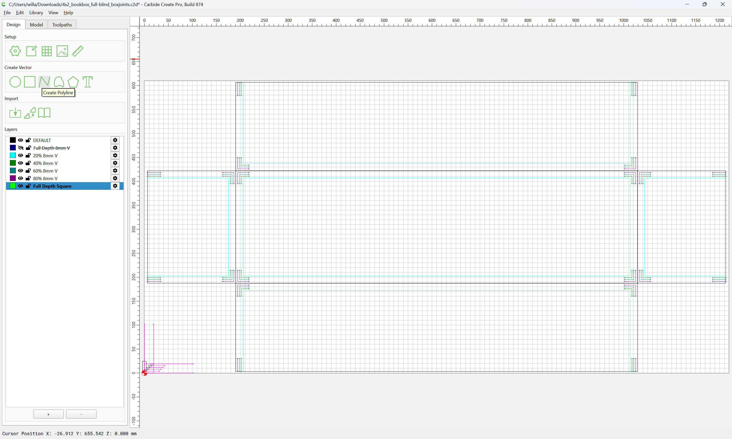
and draw lines at the edge of where the cut will be made:
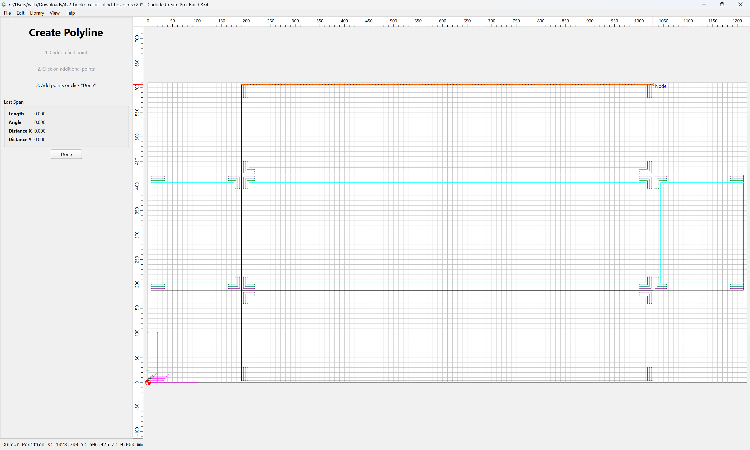
Done
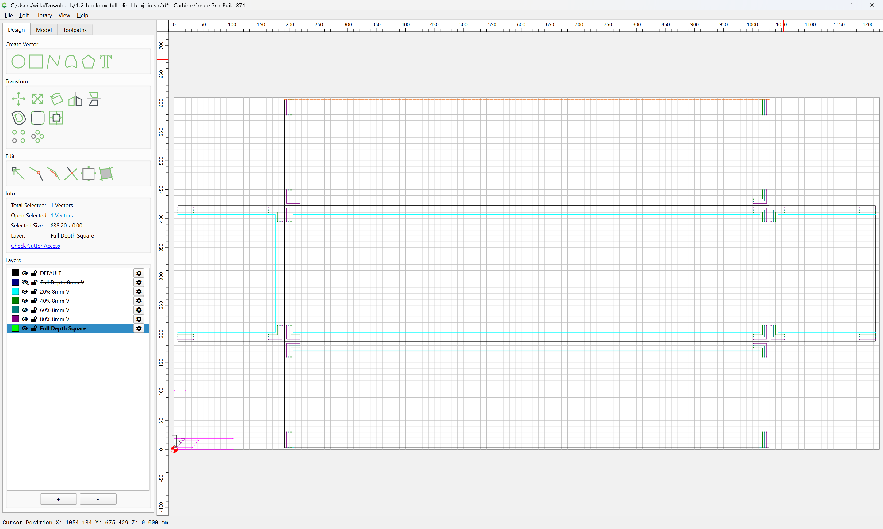
repeating until we have:
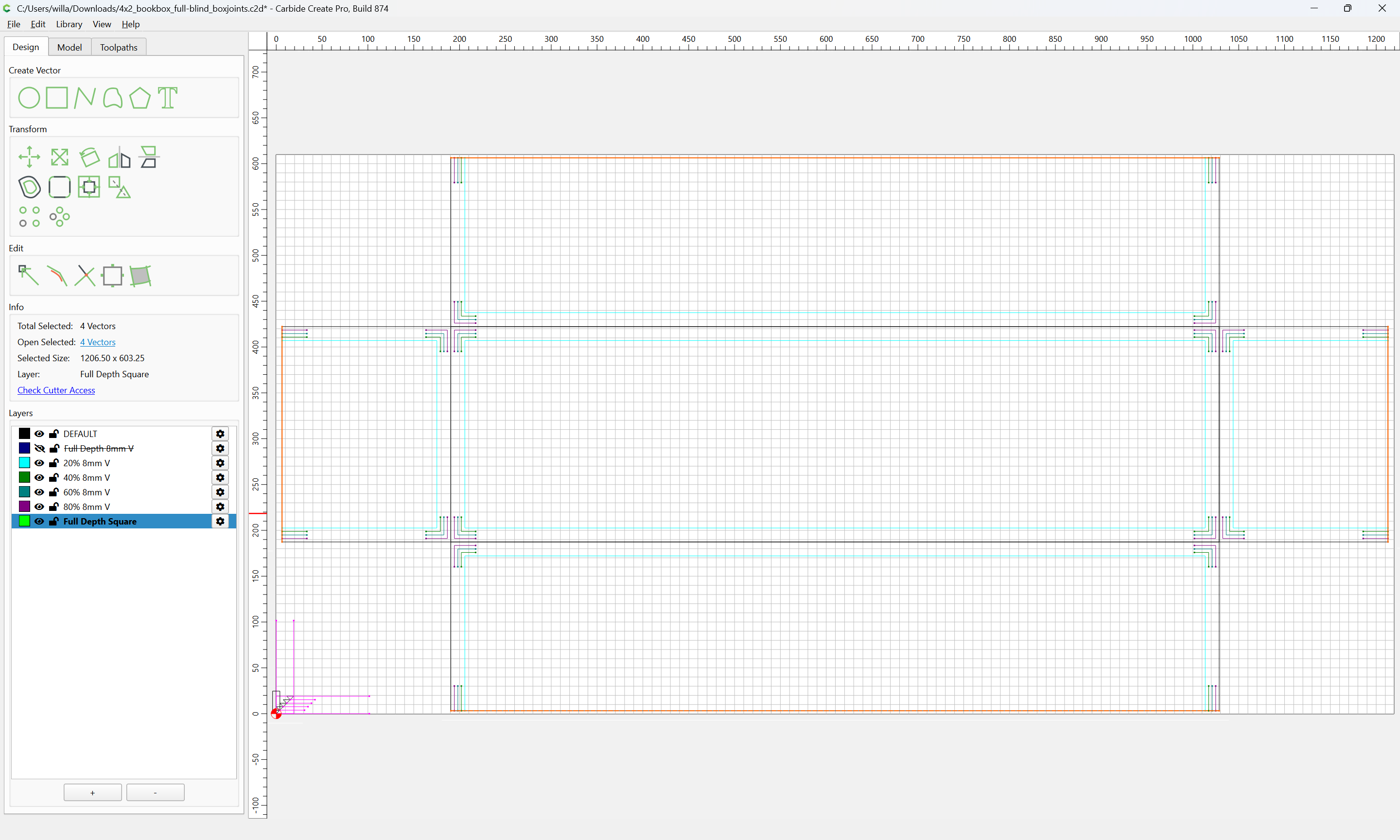
Then we set up a Contour toolpath:
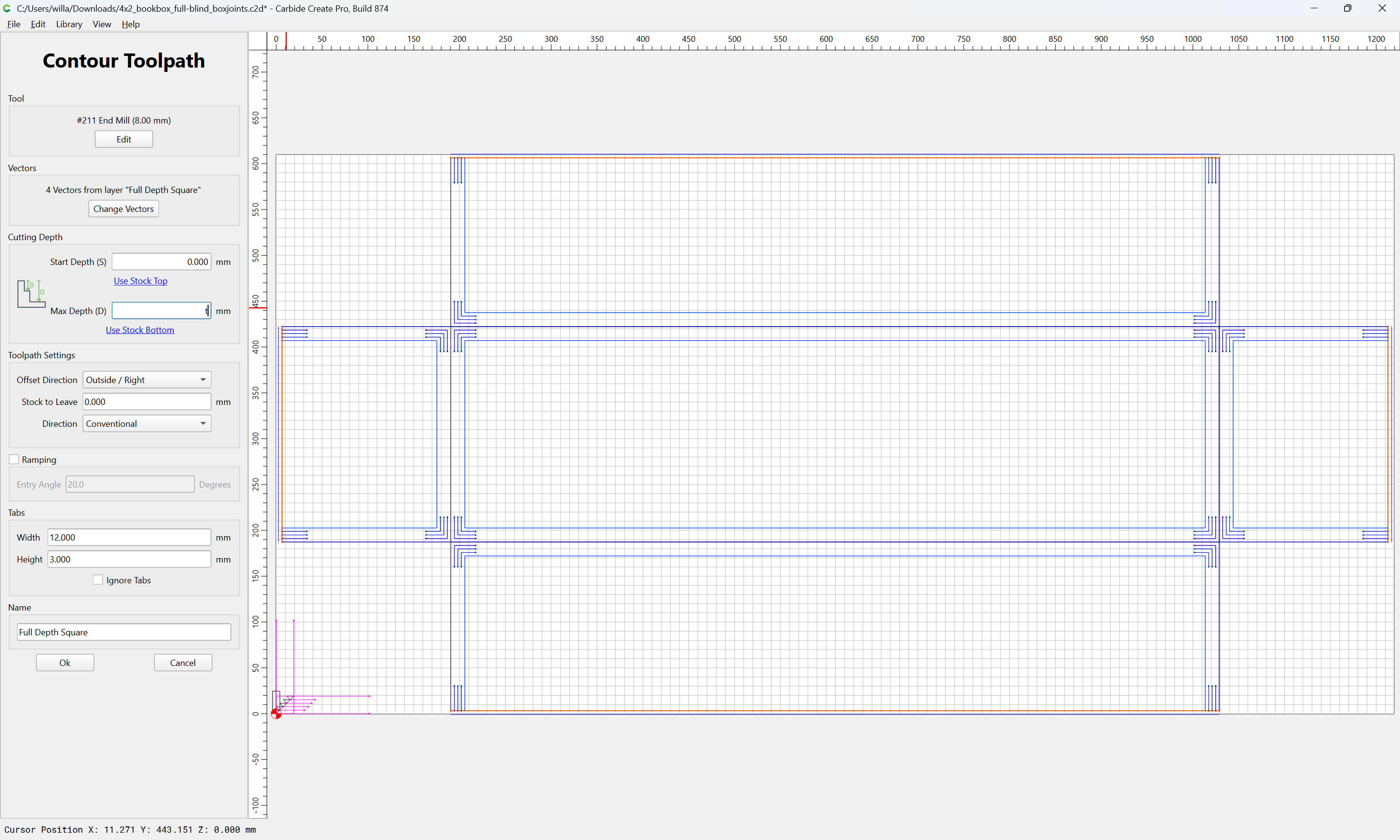
(If the side placement is wrong, go back to the Design tab and reverse the relevant paths)
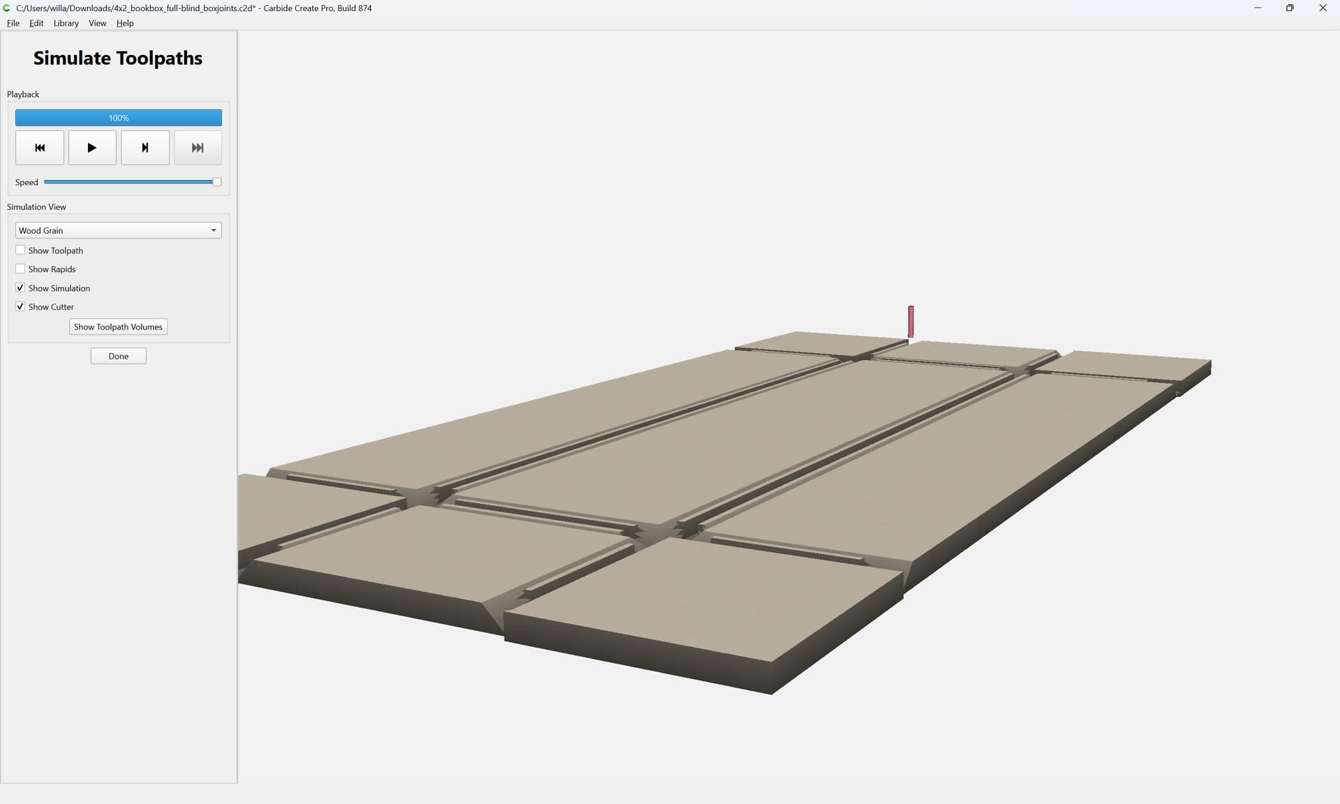
this previews as:
In order to make the shallow depth cut one will want outlines which describe the above Full Depth Square toolpaths which will need to be endmill diameter plus 10%:
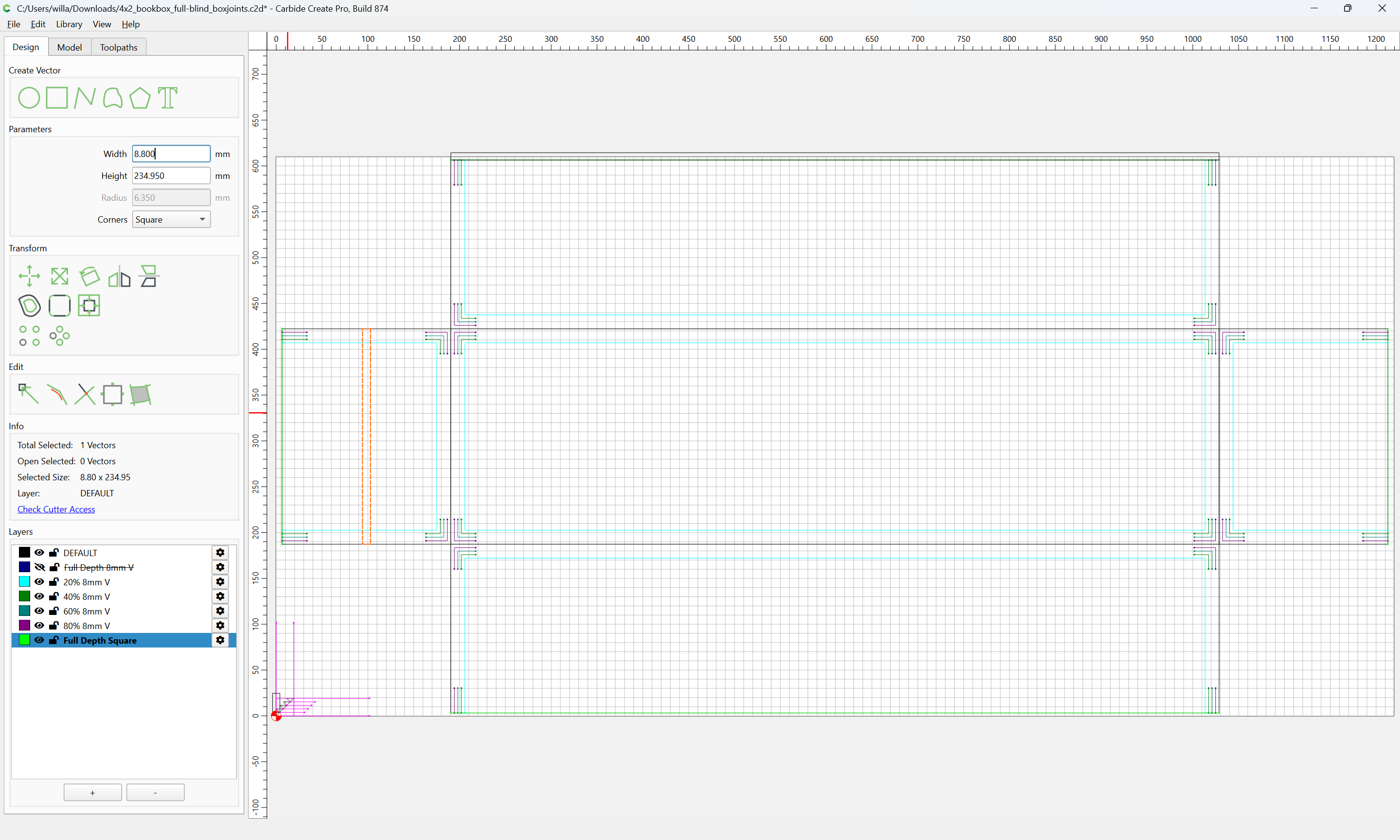
and that much taller:
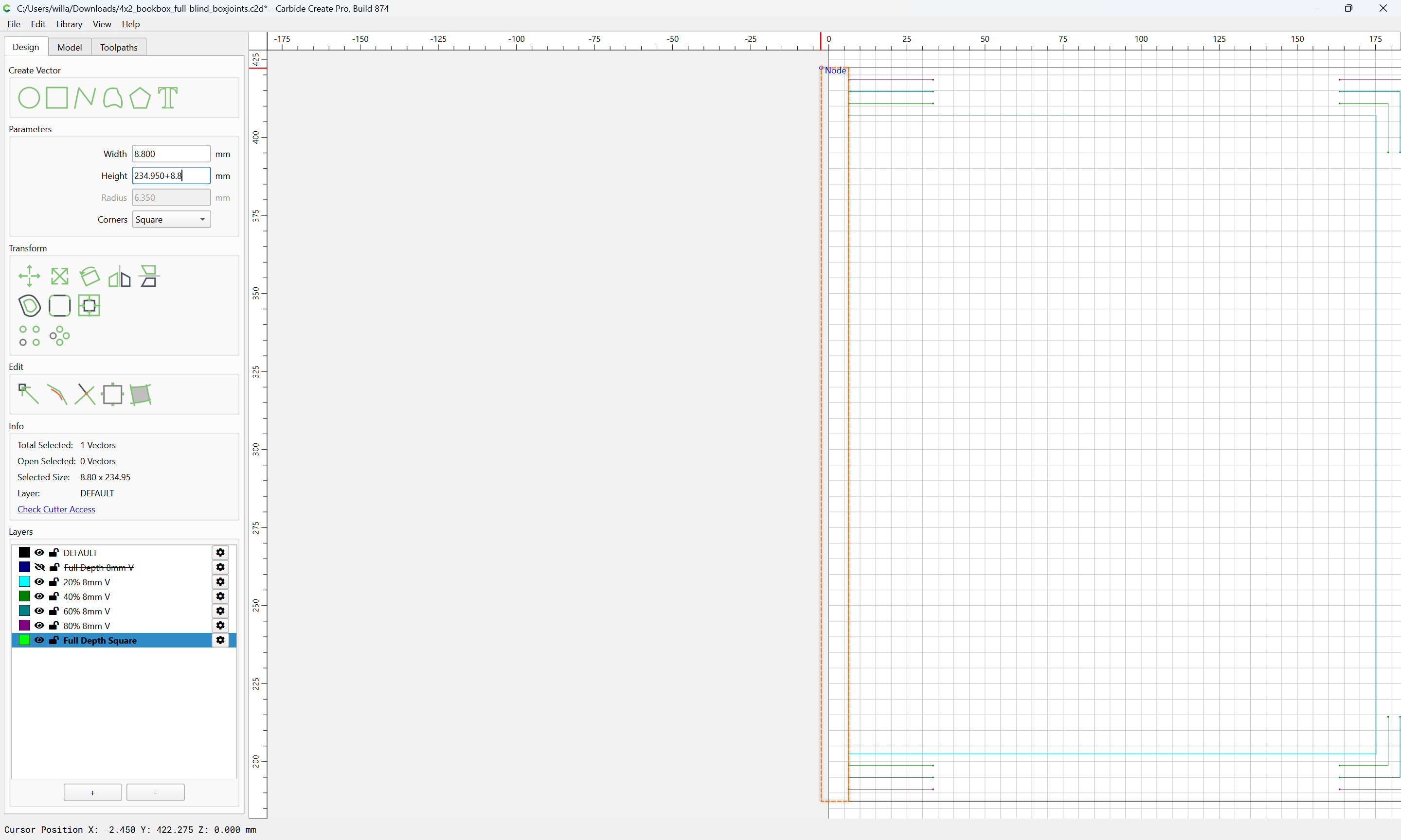
and radiused:
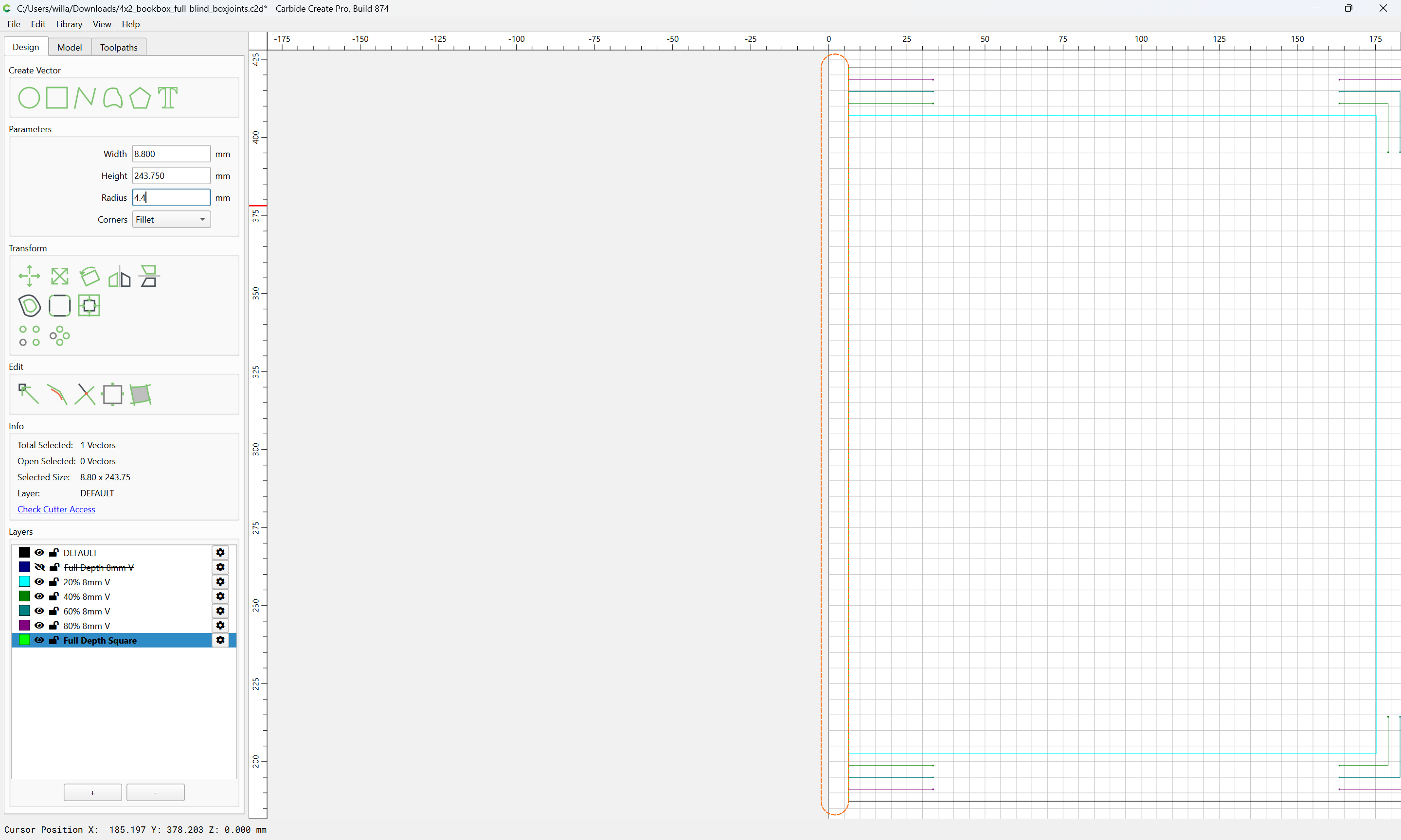
Place at each edge:
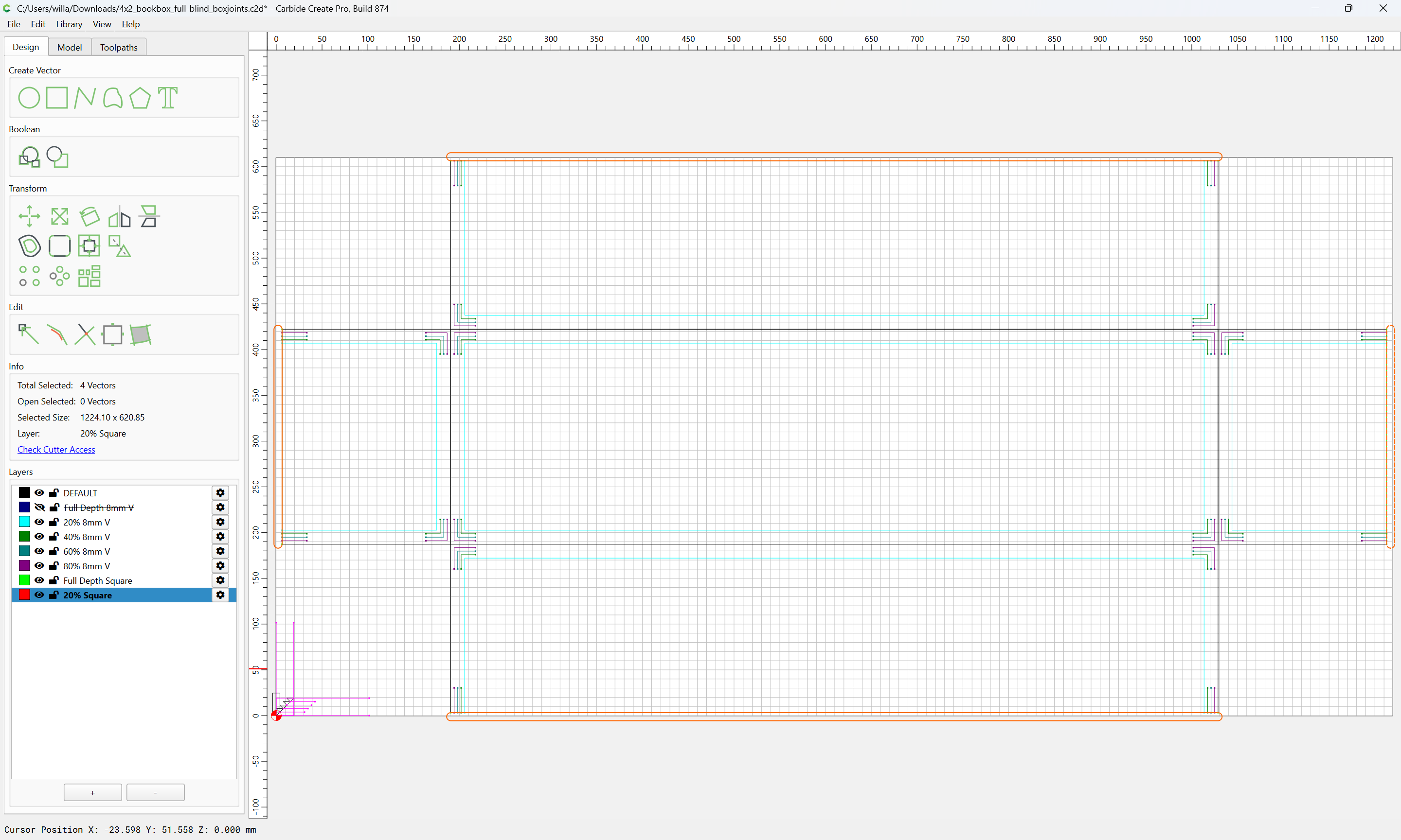
and fill in where the Full-Depth V cuts are made:
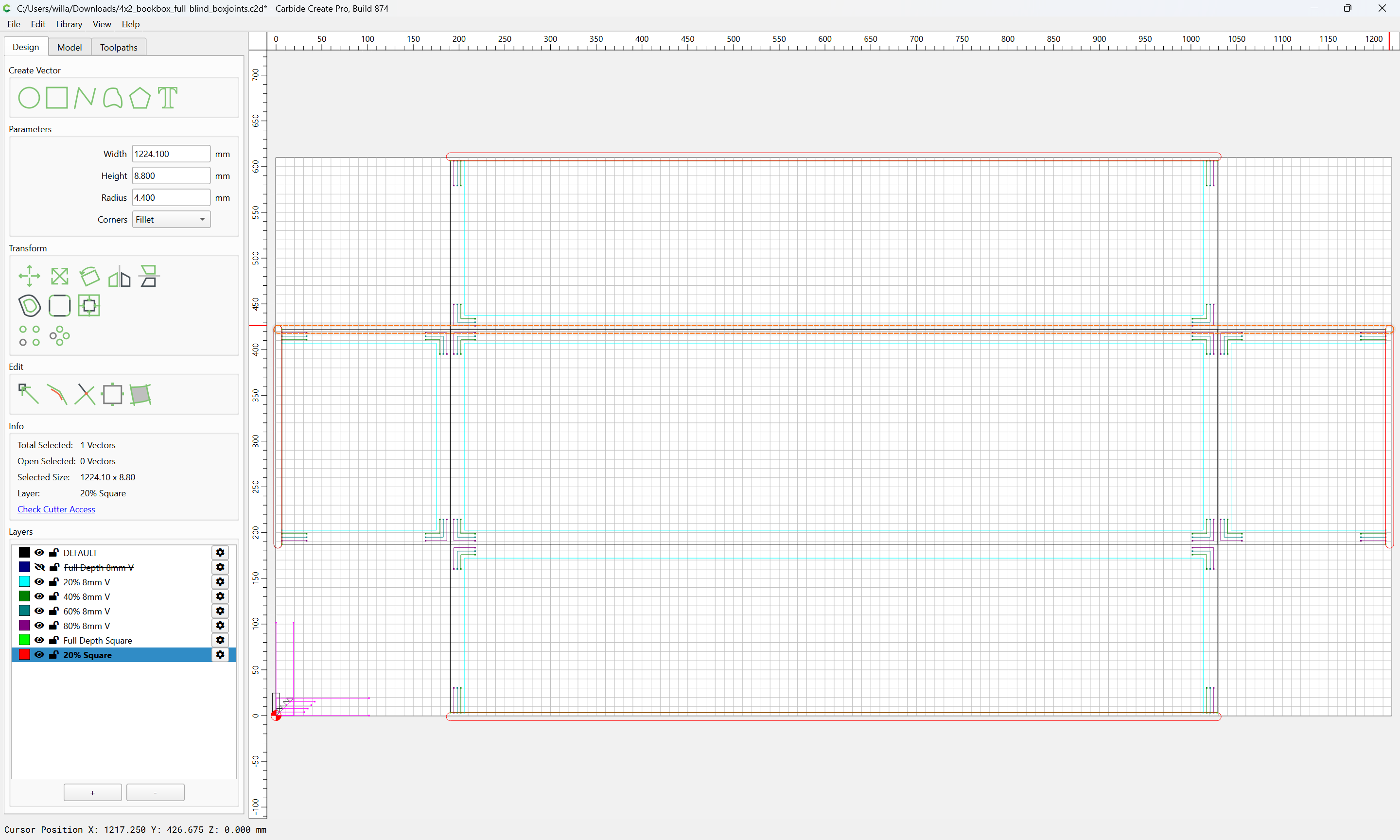
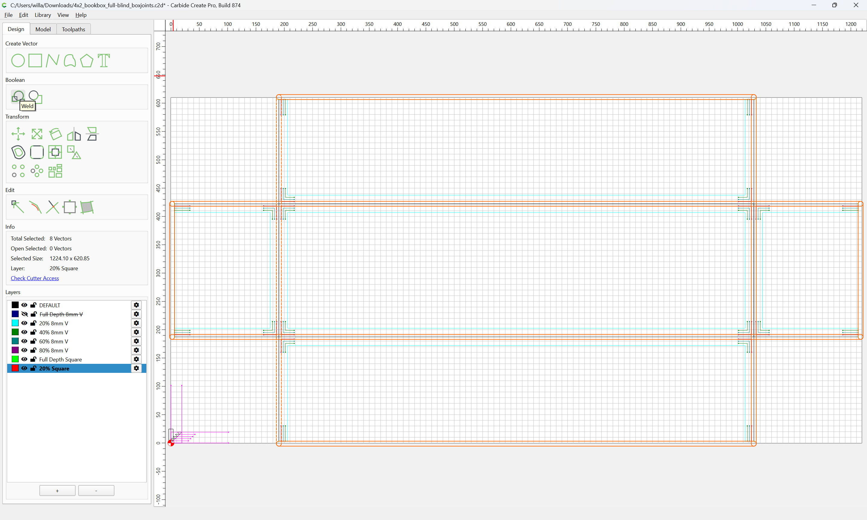
Then use Boolean Union:
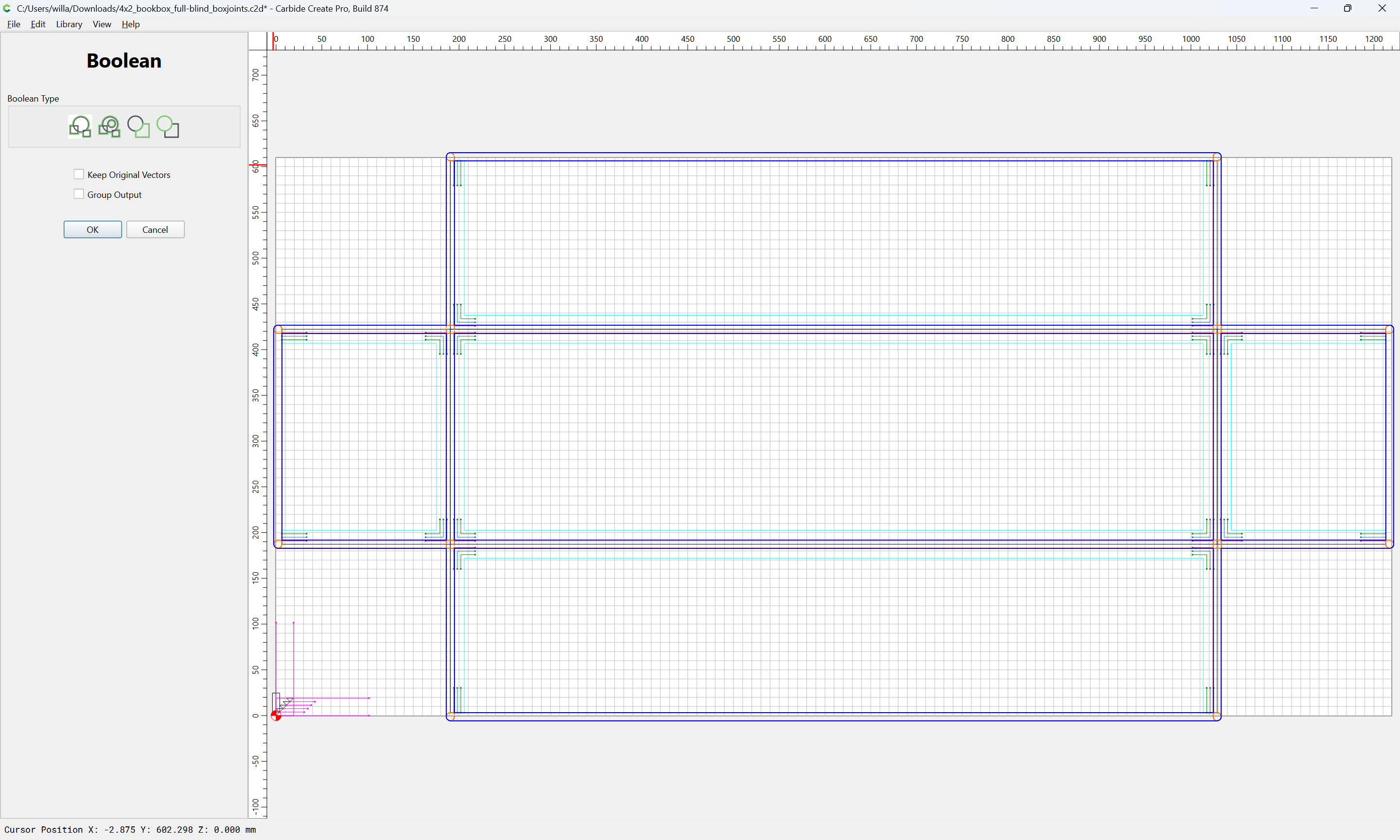
OK

to create the desired outline on which we shift-click to remove it from the selection:
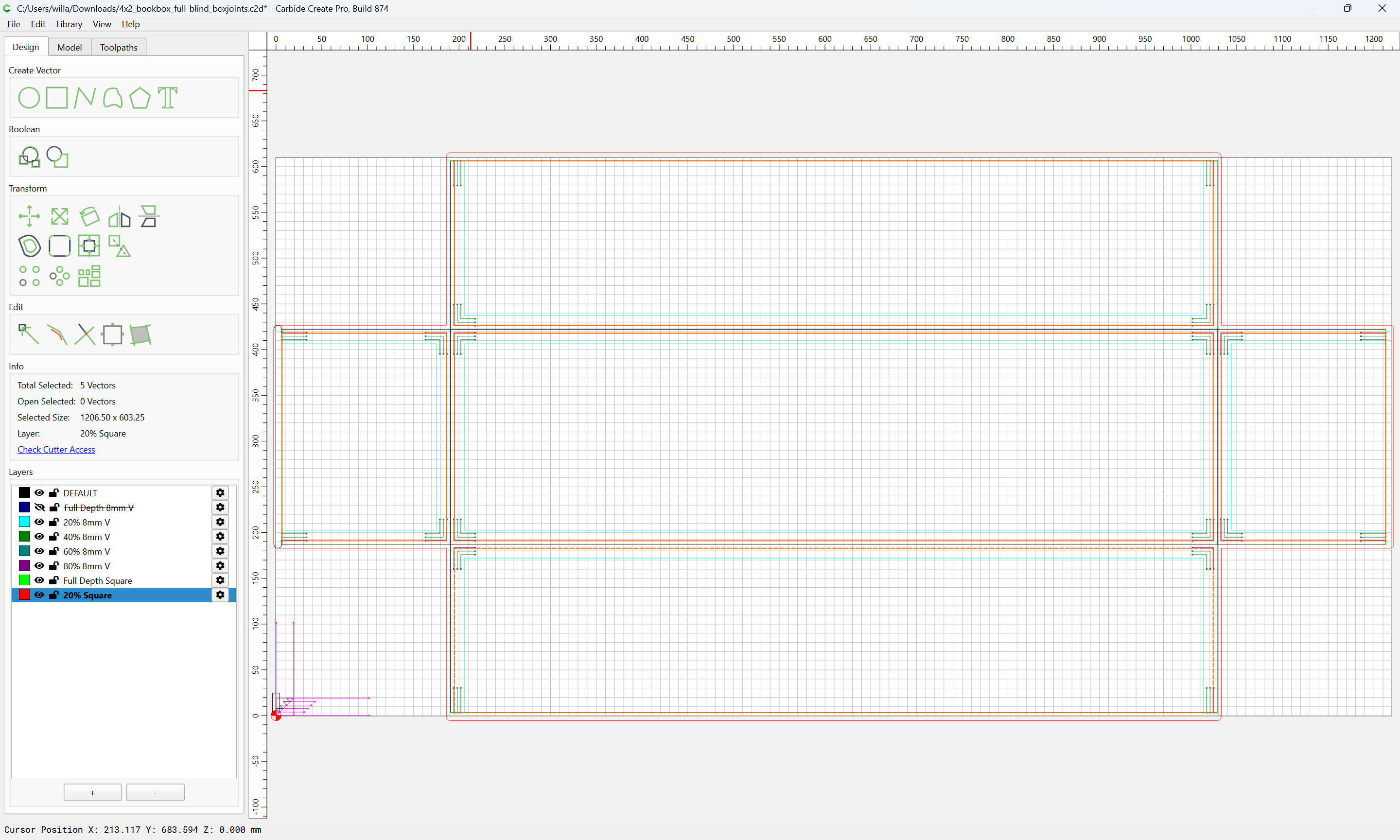
and then delete:
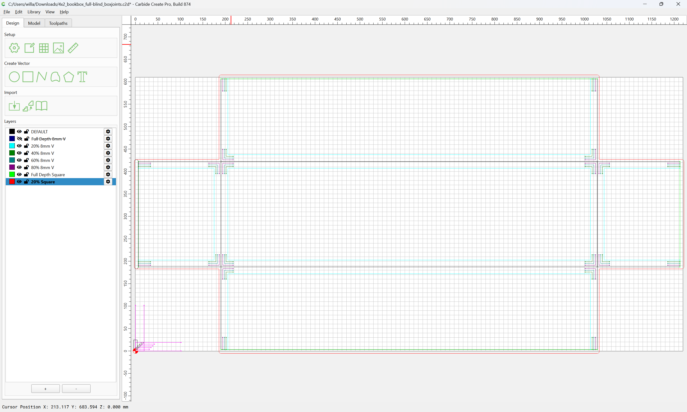
For the interior we will need the 20% V-tool geometry:
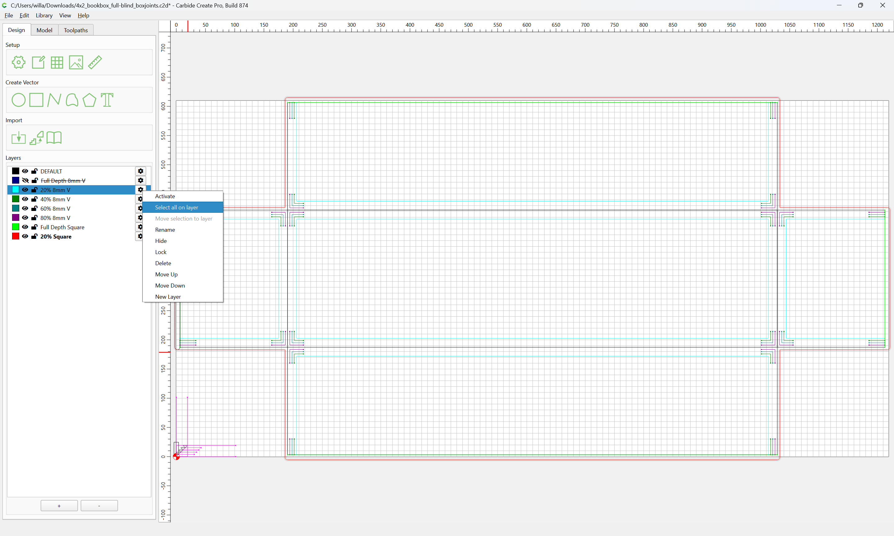
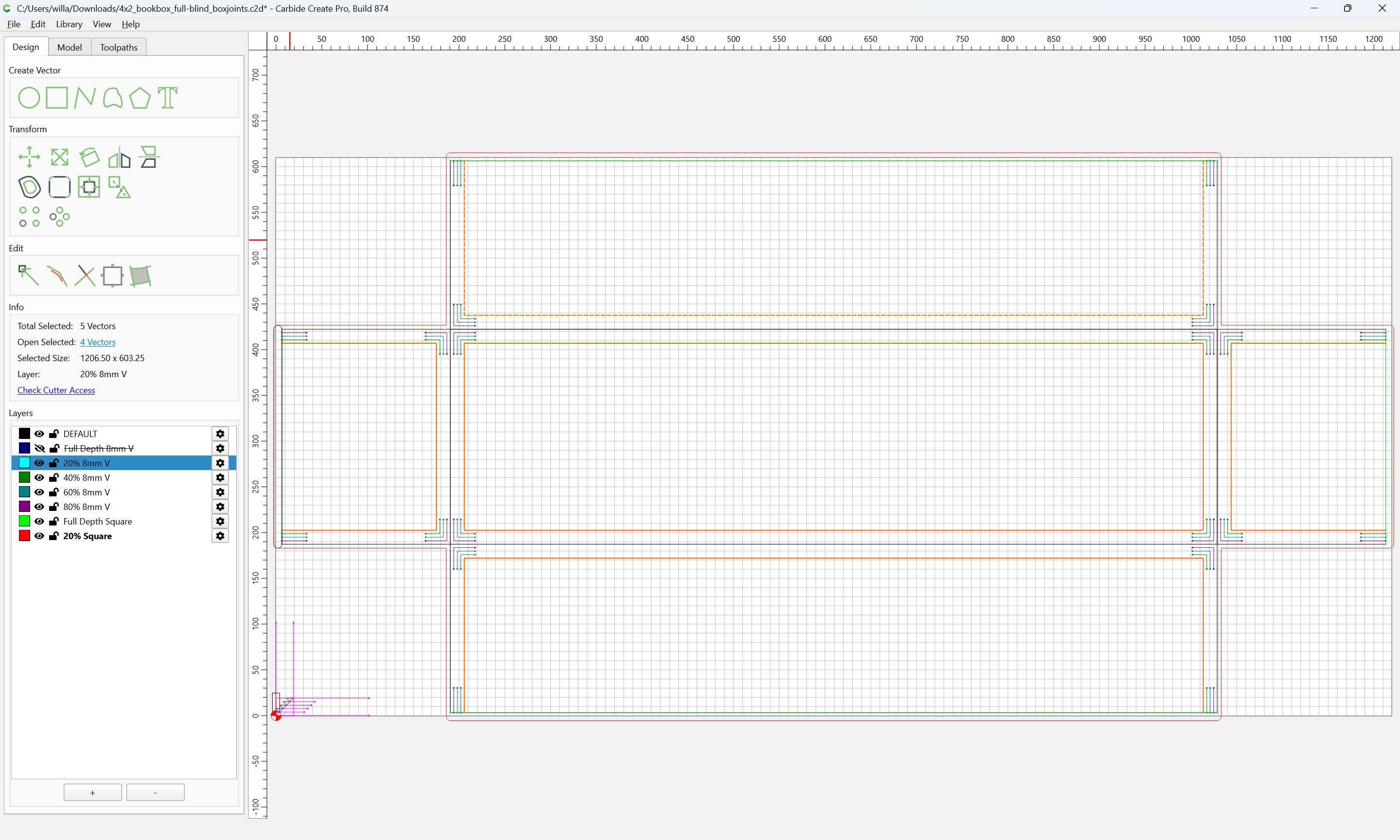
which we will copy and paste in place:
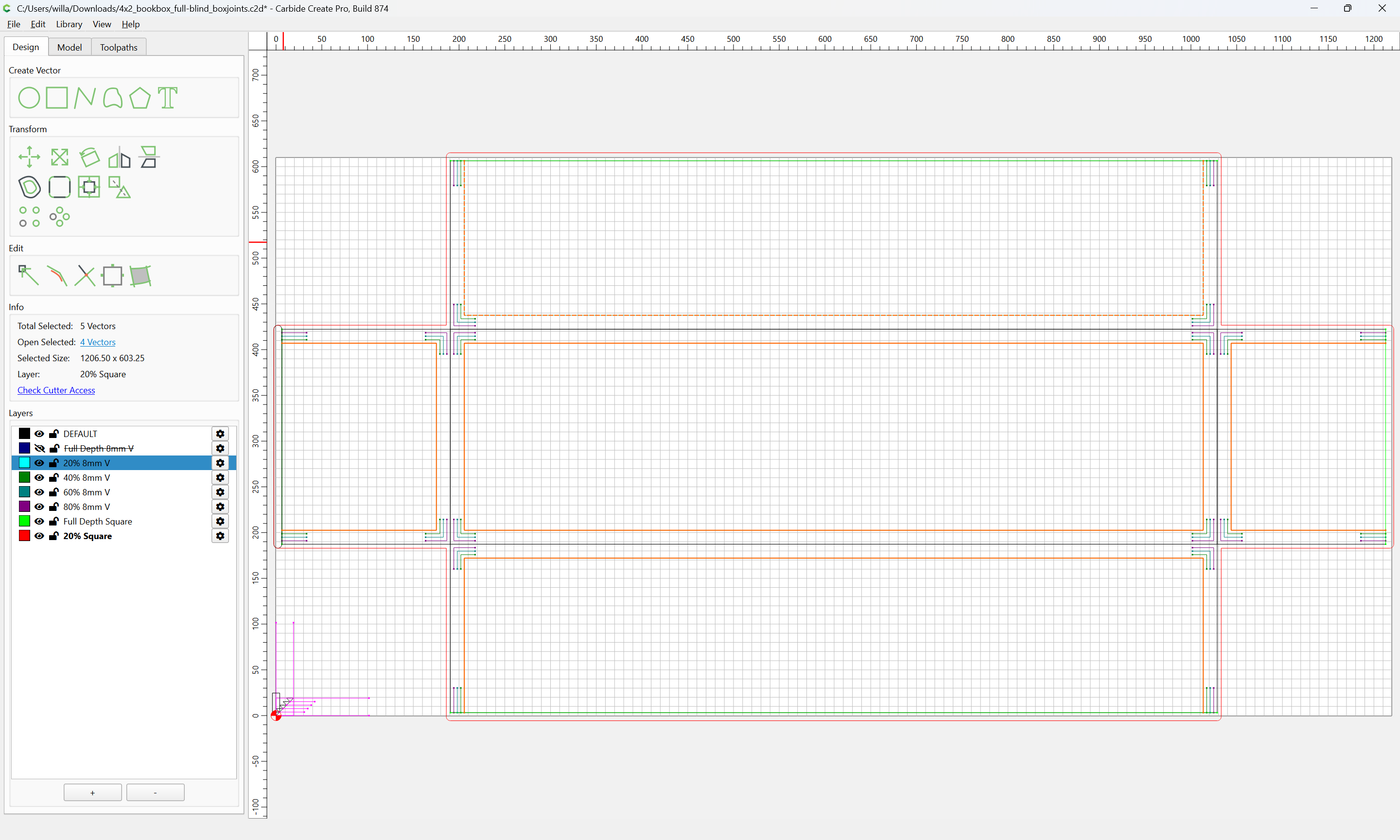
and to verify that this was successful, hide the 20% Square layer:

Then hide the 20% V layer:
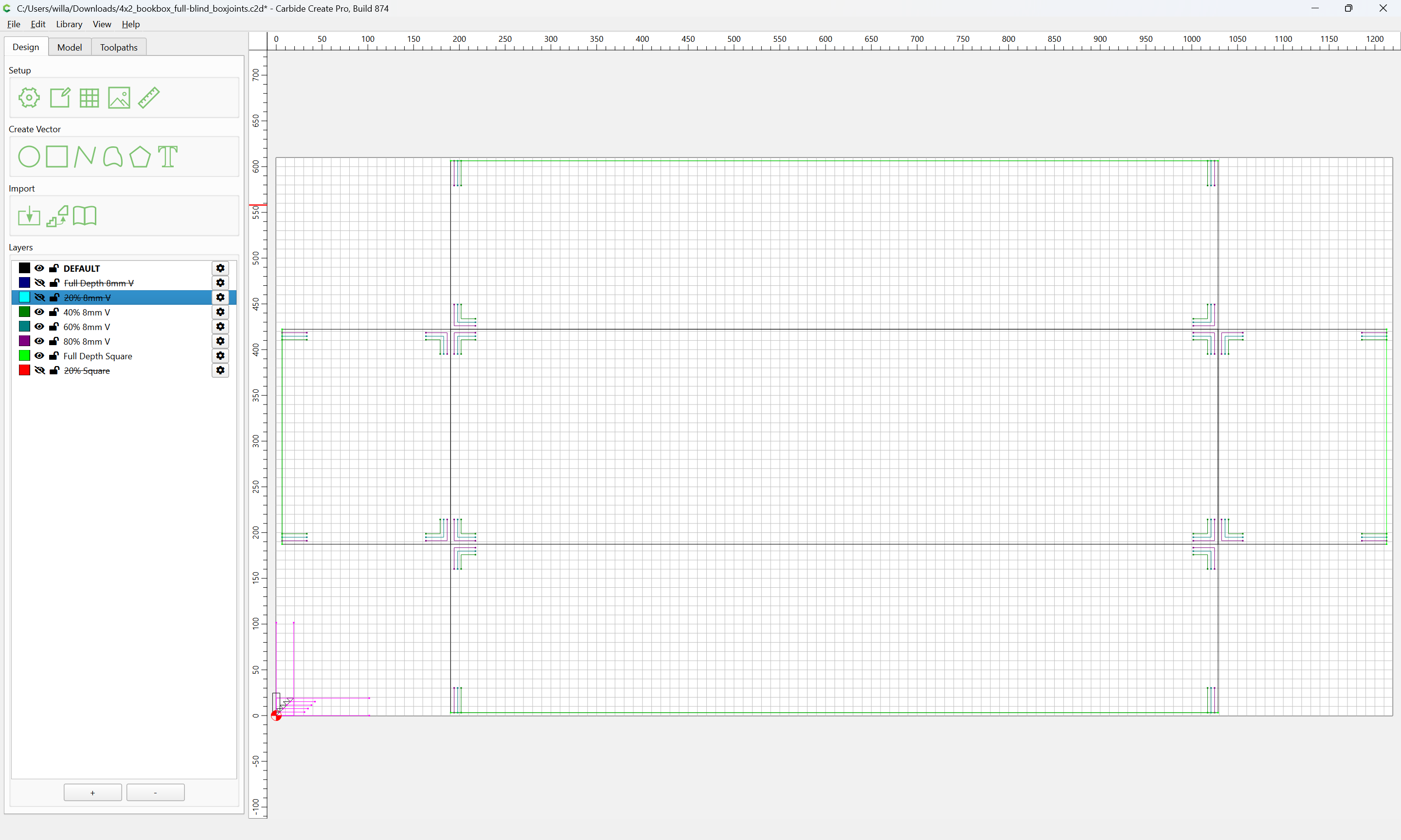
then show the 20% Square layer:
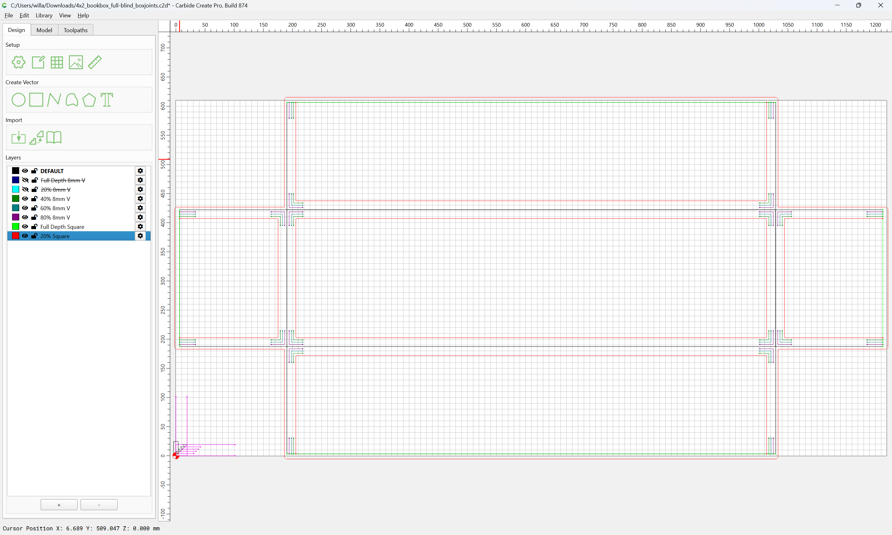
Select each open region:
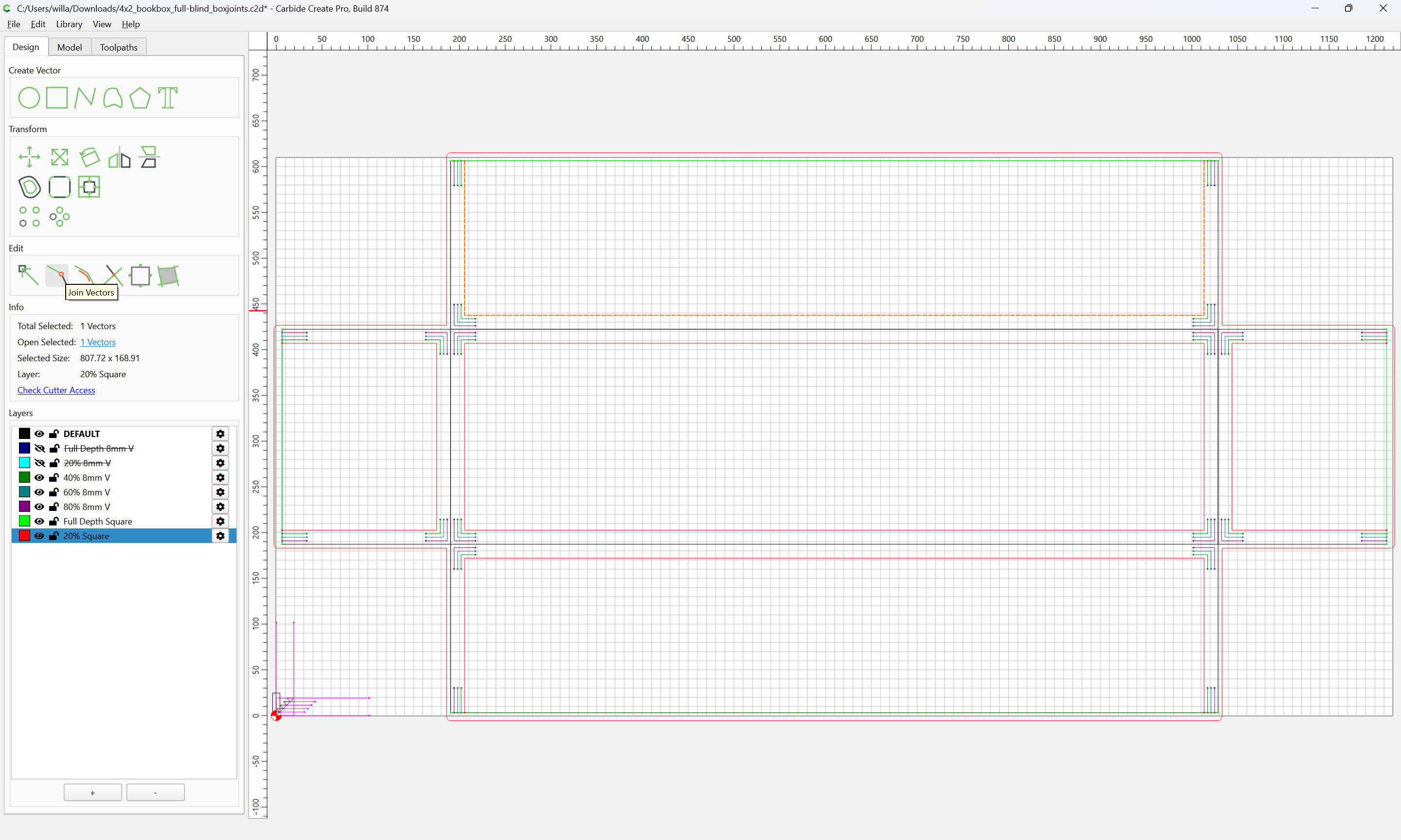
and use Join Vectors to close:
Yes
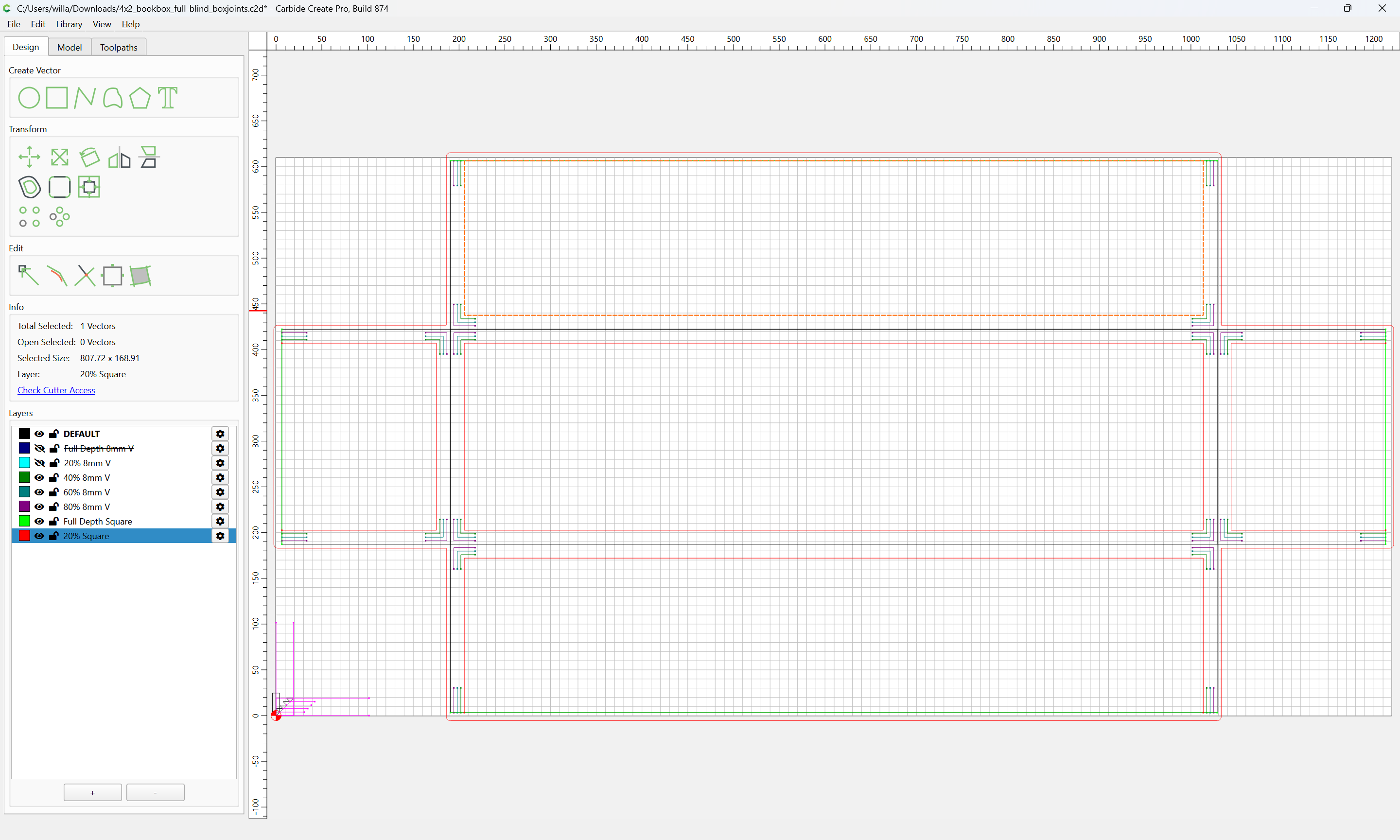
Repeating until we arrive at:
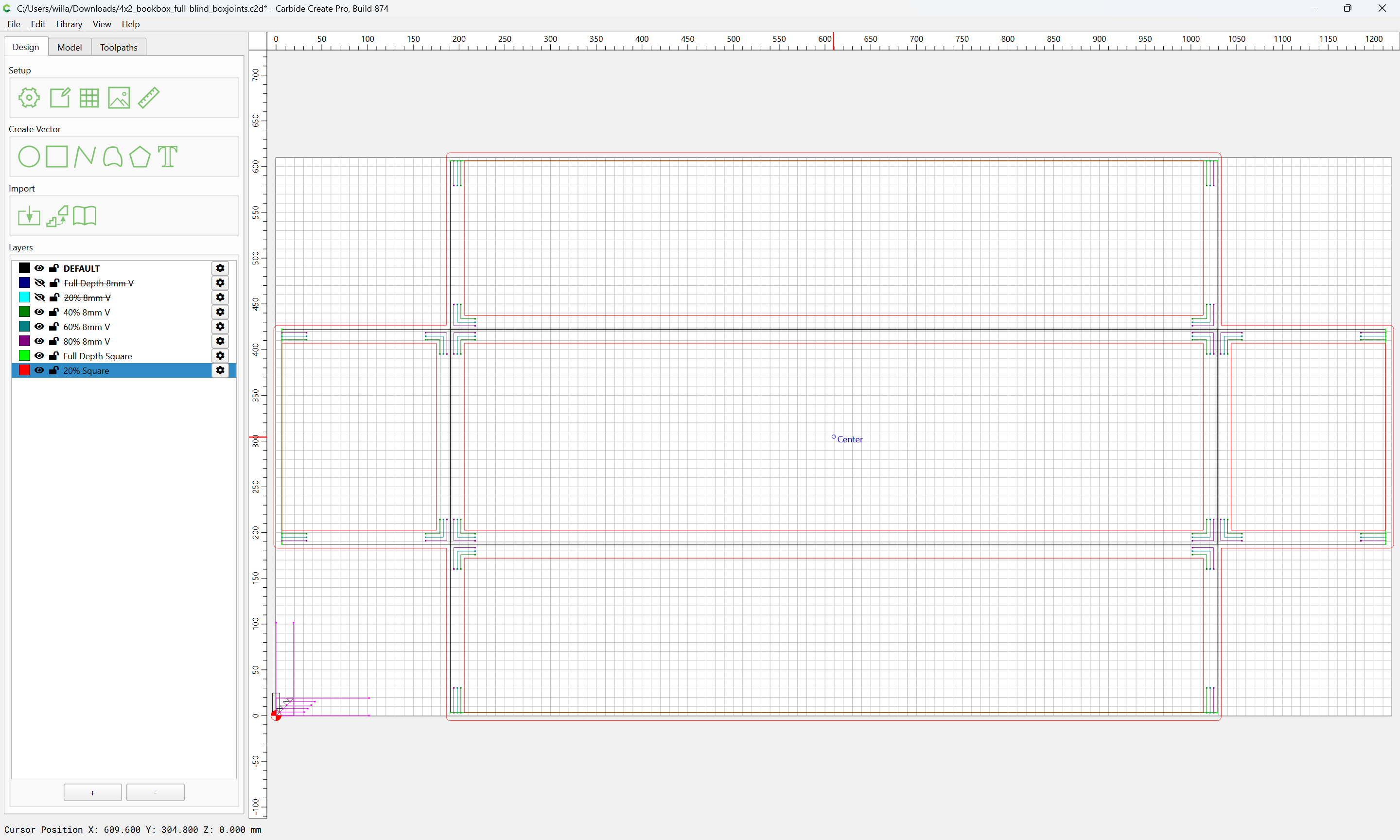
Assign a Pocket toolpath:
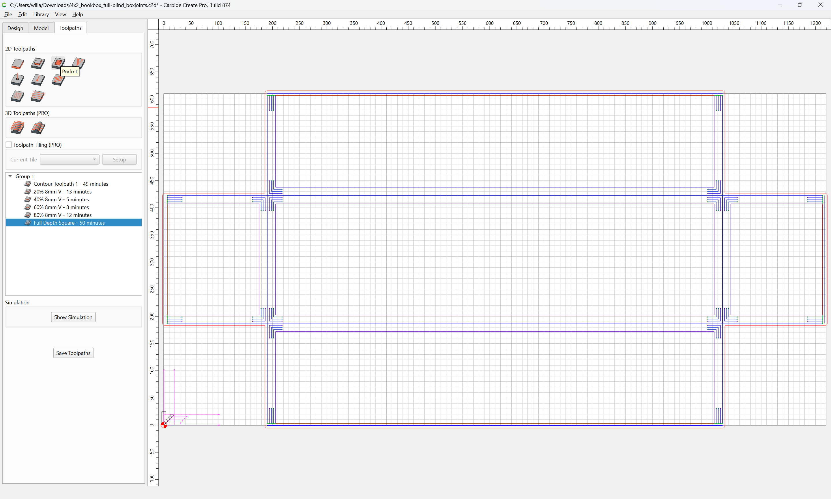
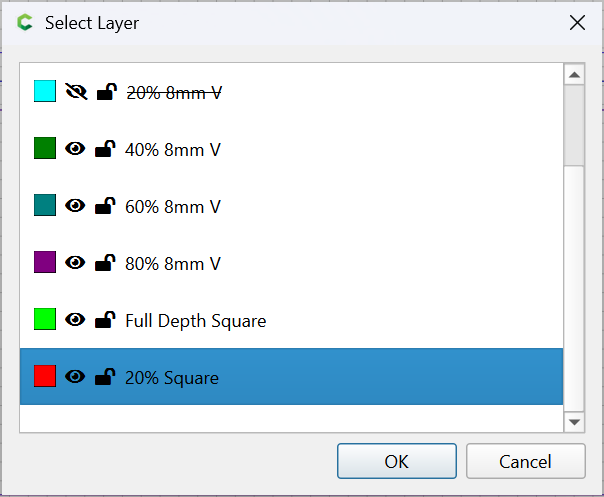
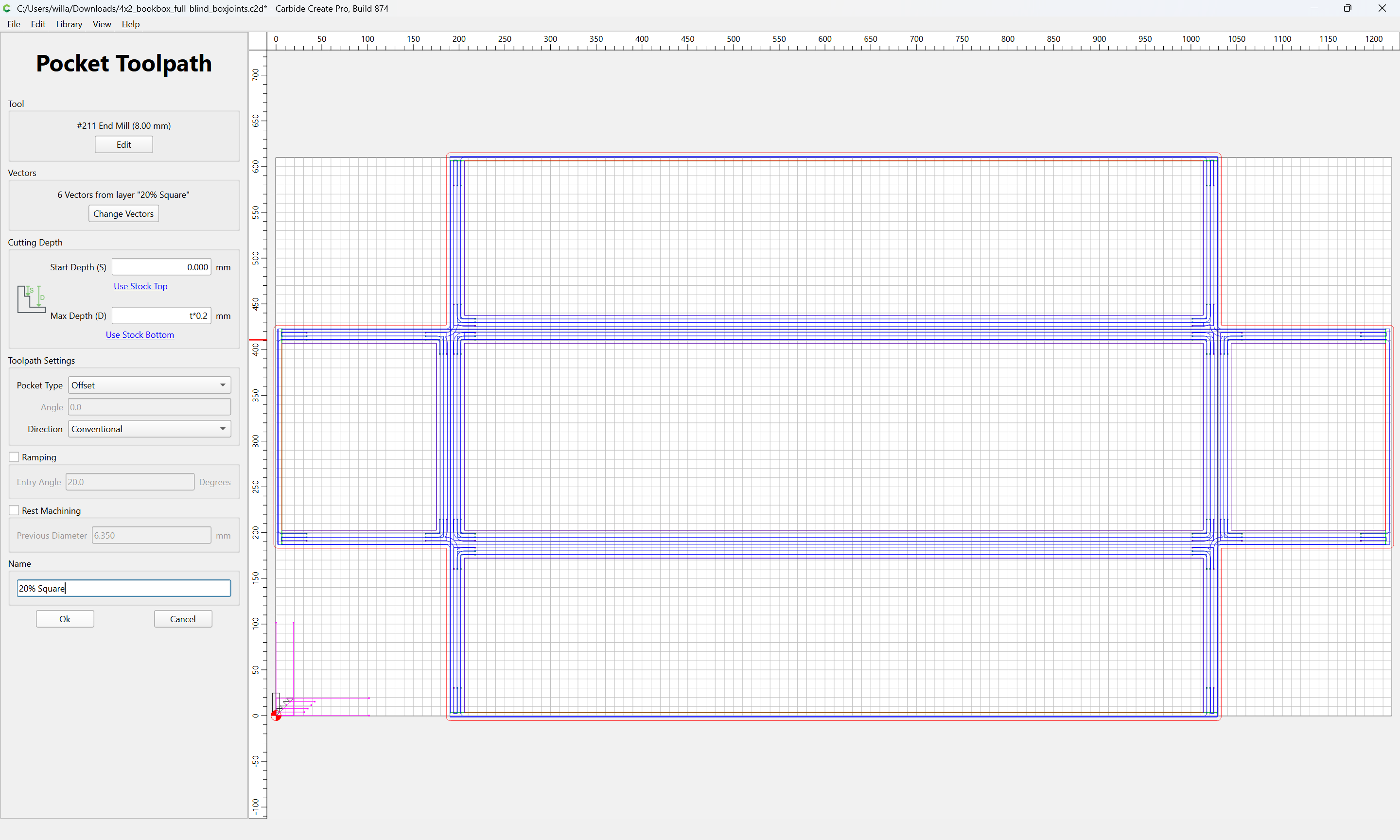
which previews as:
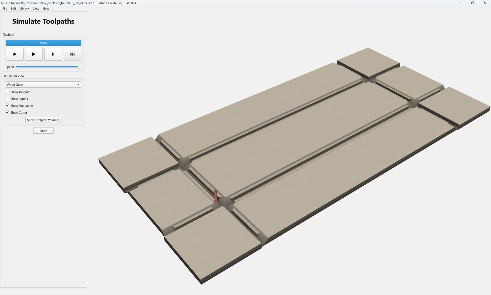
Lastly we draw in the geometry for cutting the box joints/recesses for same.
At each corner there will be a Stock Thickness square area which is described by the miter:
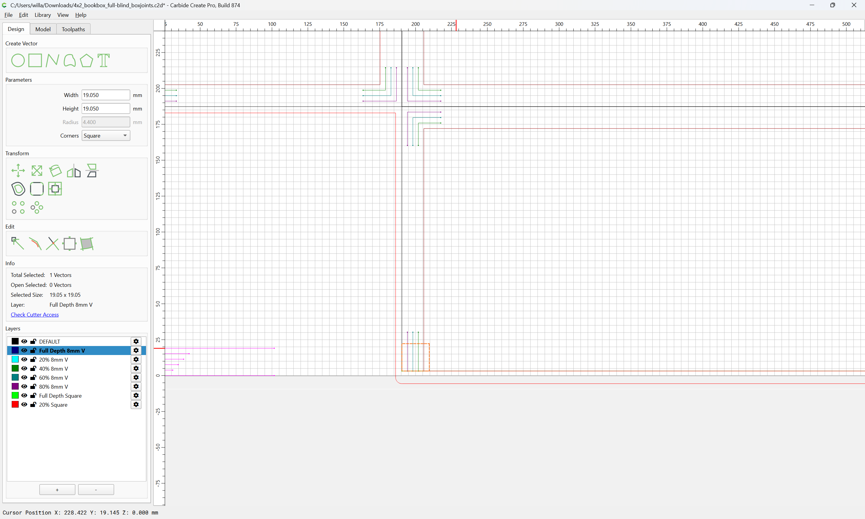
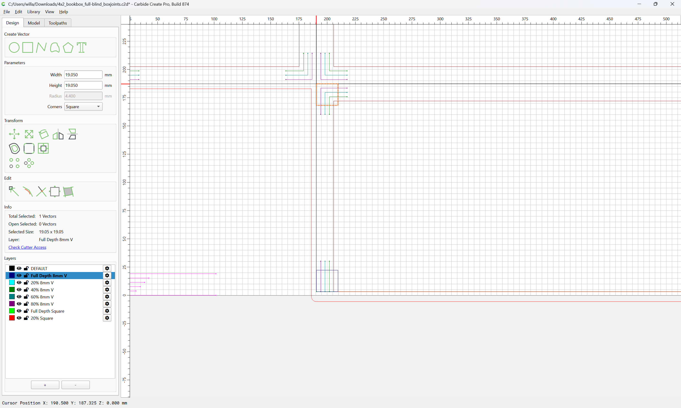
In-between those two squares it will be necessary to cut a pair of alternating regions which are best described as a series of rectangles which are Stock Thickness wide (across the joint) and endmill diameter tall (along the axis of the joint):
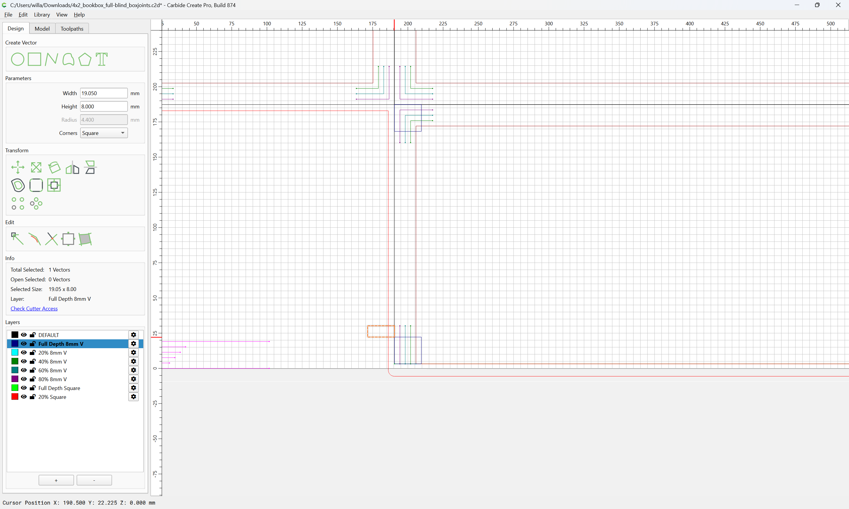
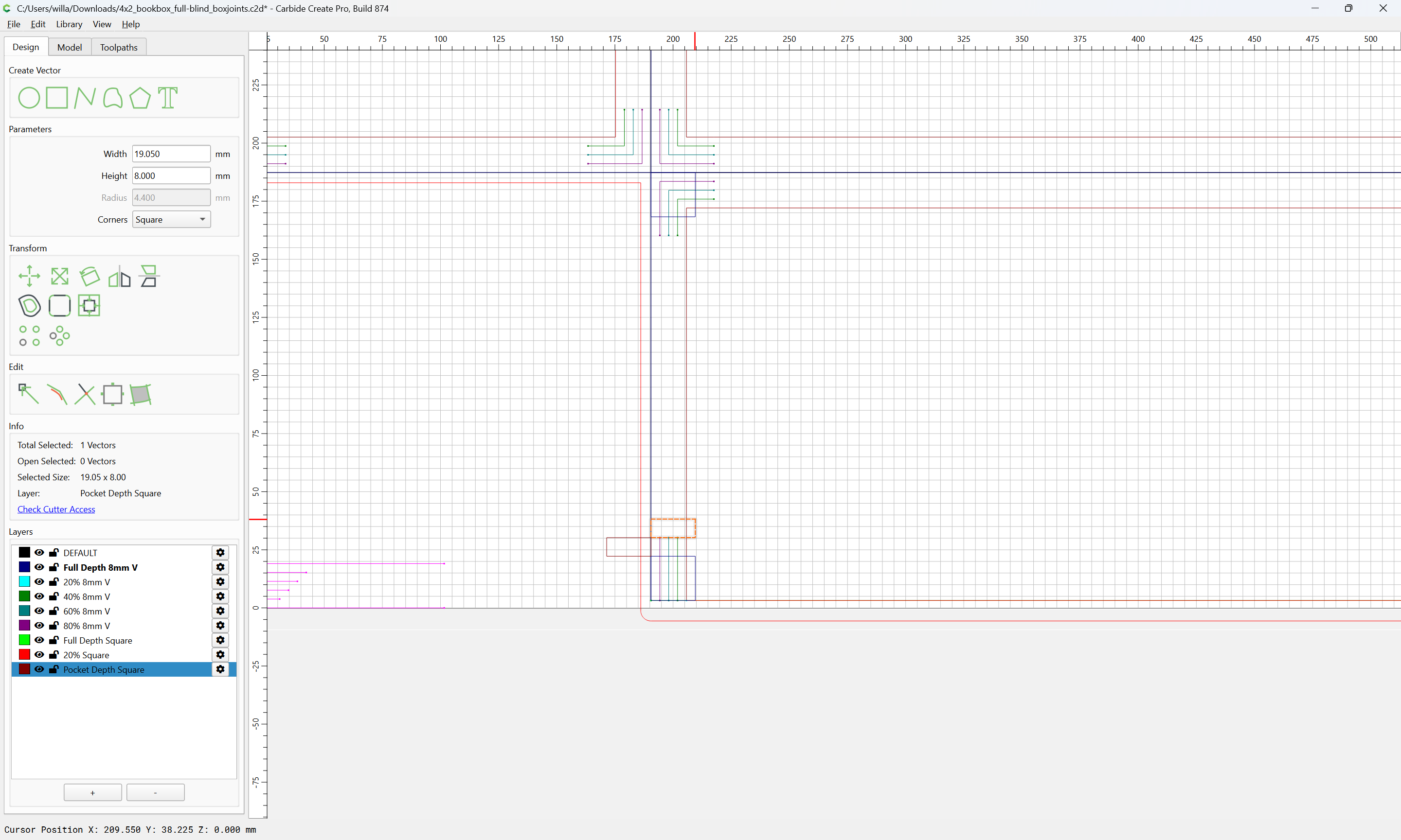
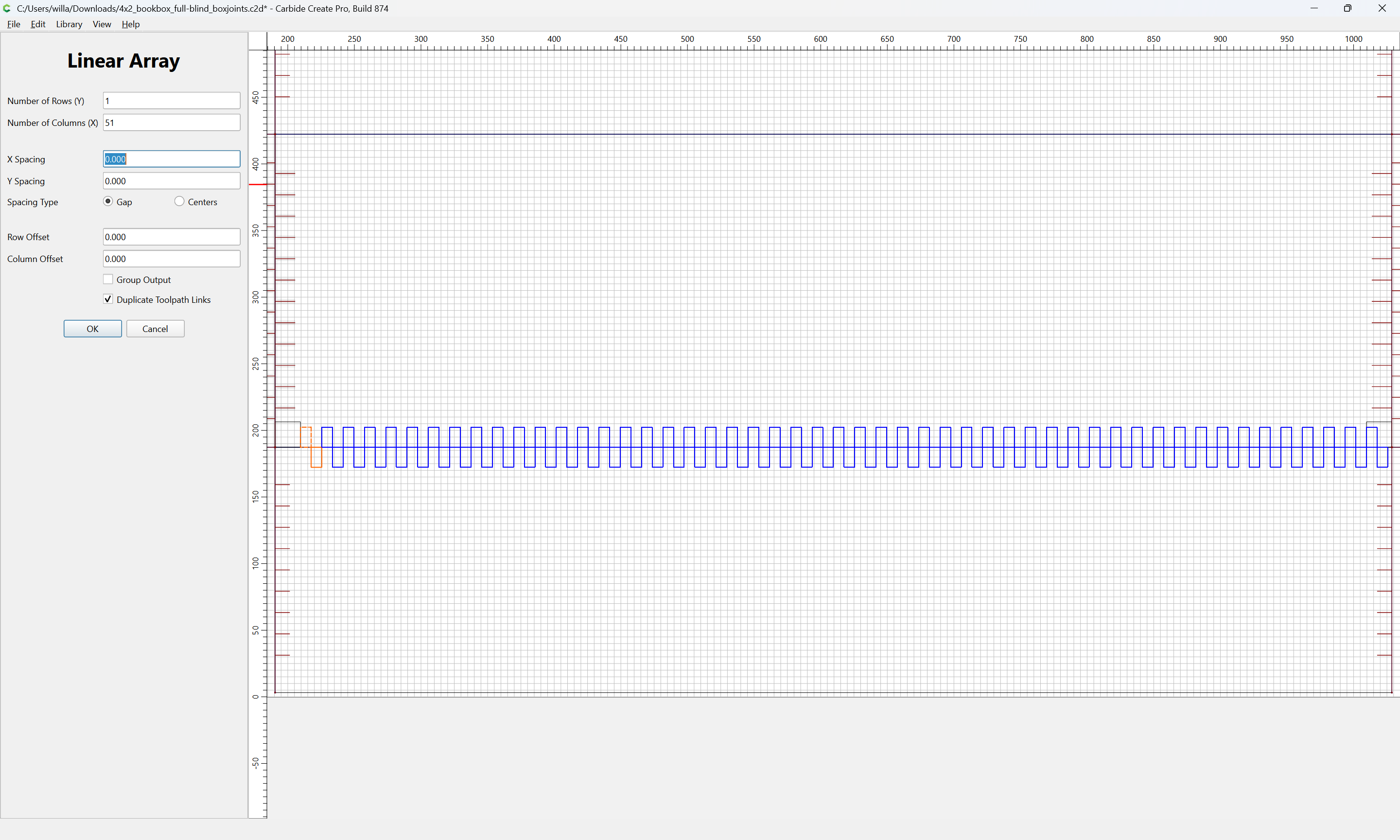
Select both and use Linear Array to make enough copies to more than fill the lacunae between the two afore-mentioned squares:
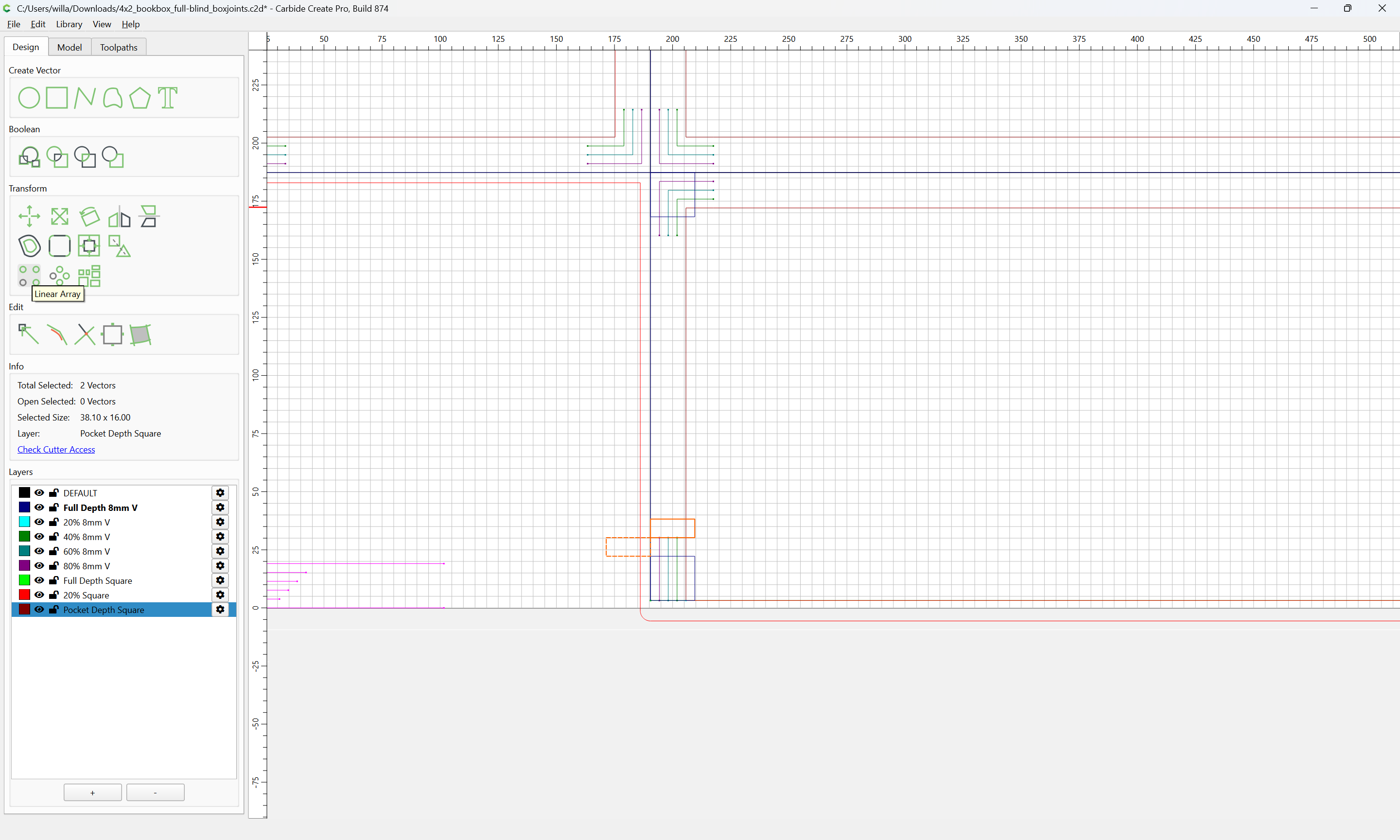
Linear Array:
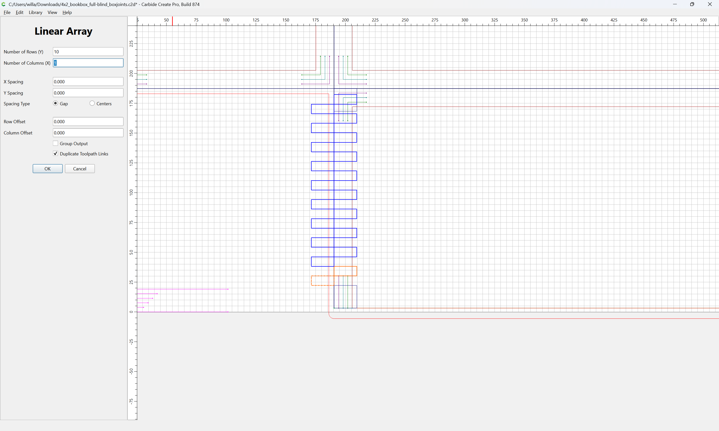
(note that it will be necessary to ignore the dimension of the top-most unit — visualization seems easier if there is an even-odd pairing)
OK
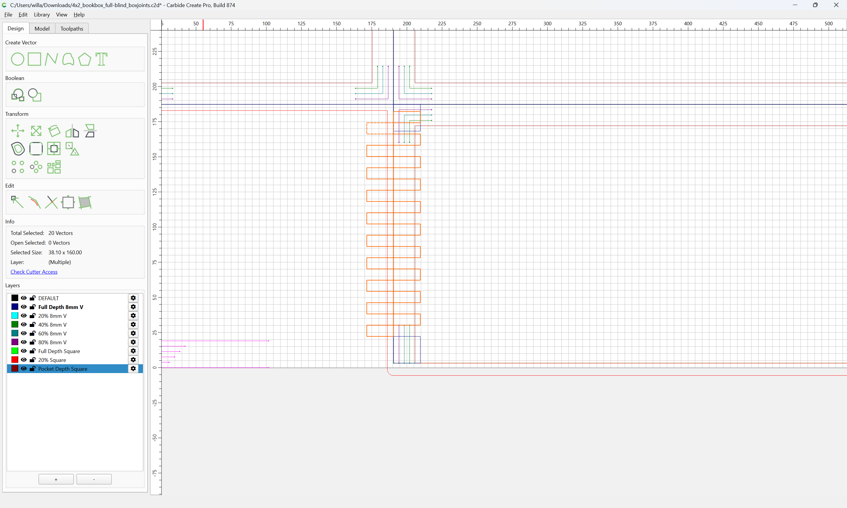
shift-click on the top-most unit to remove from the selection:

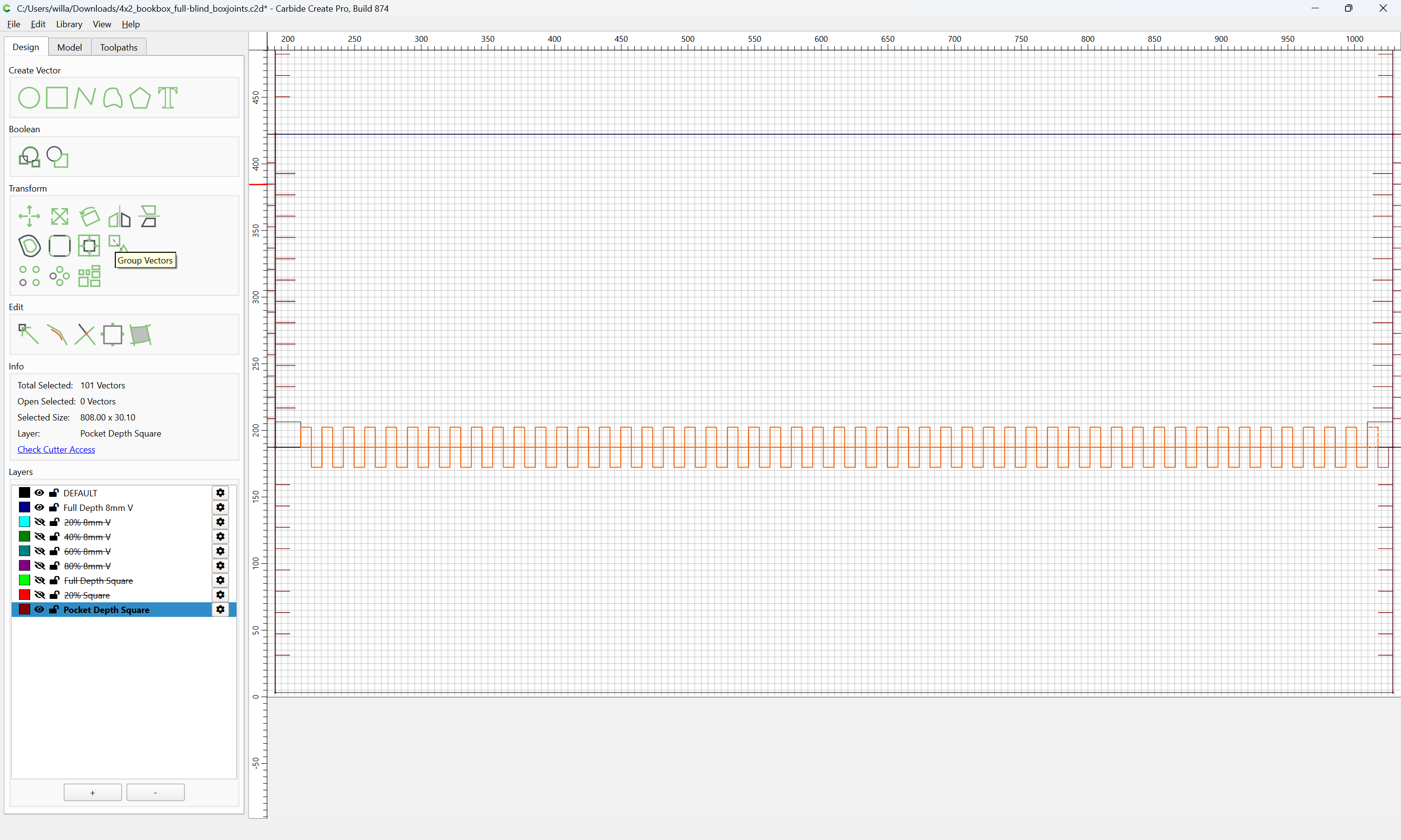
and Group Vectors
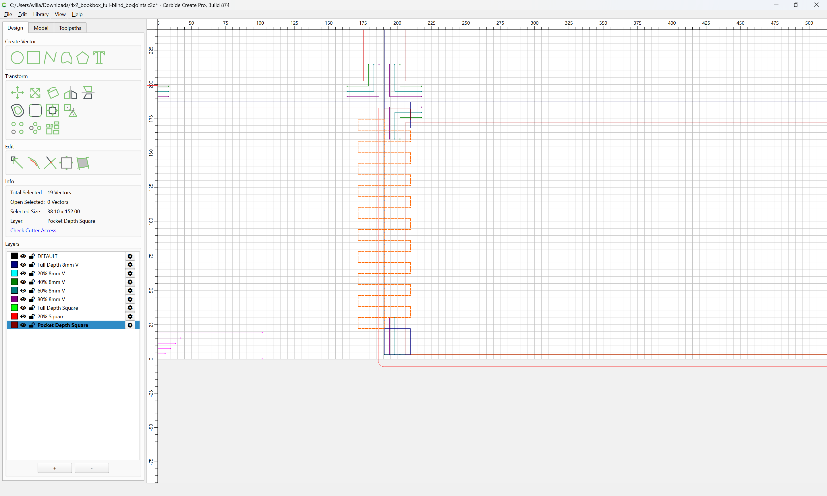
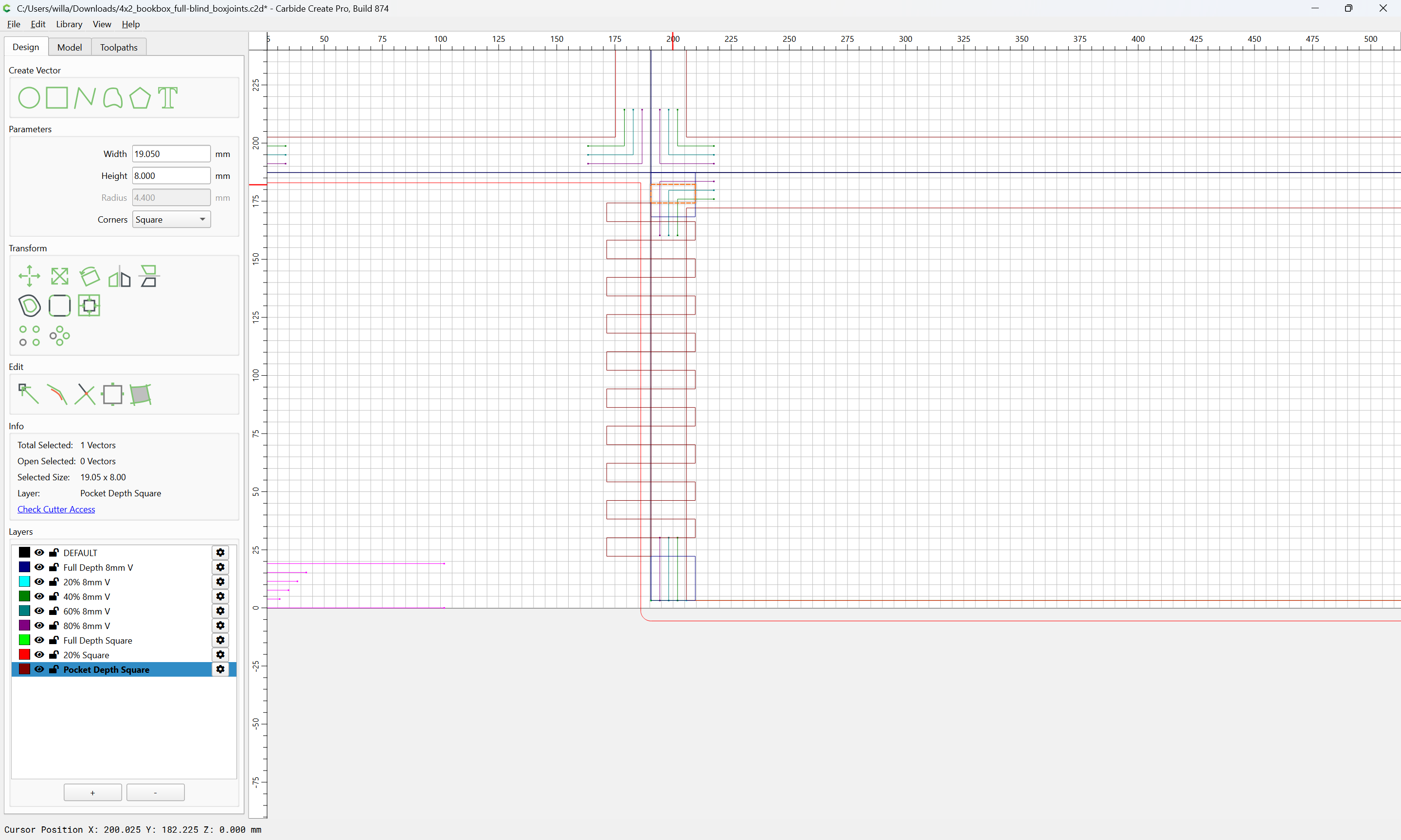
Select and delete the top-most unit:
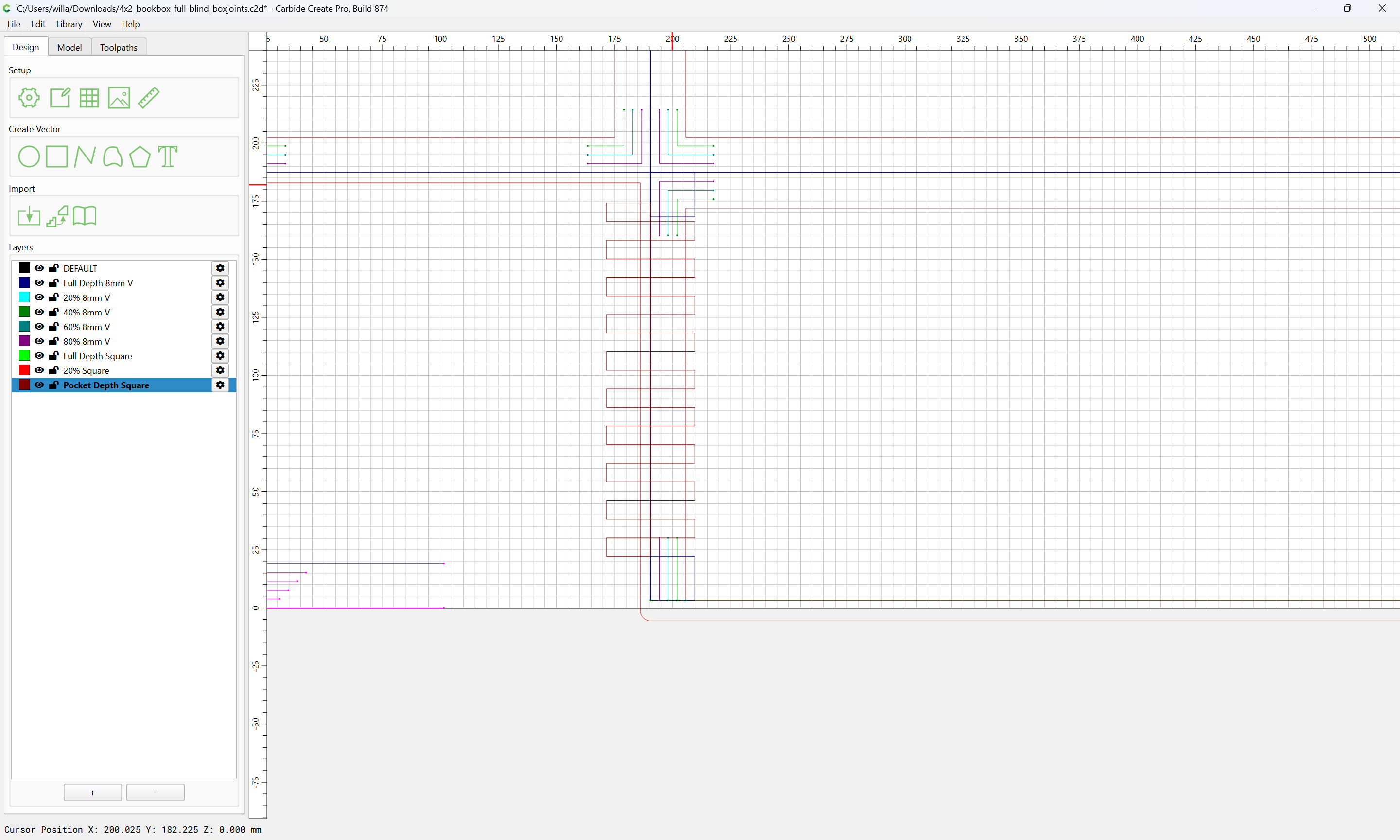
Hide all layers except for the DEFAULT (where the part outlines are) and the Pocket Depth Square:
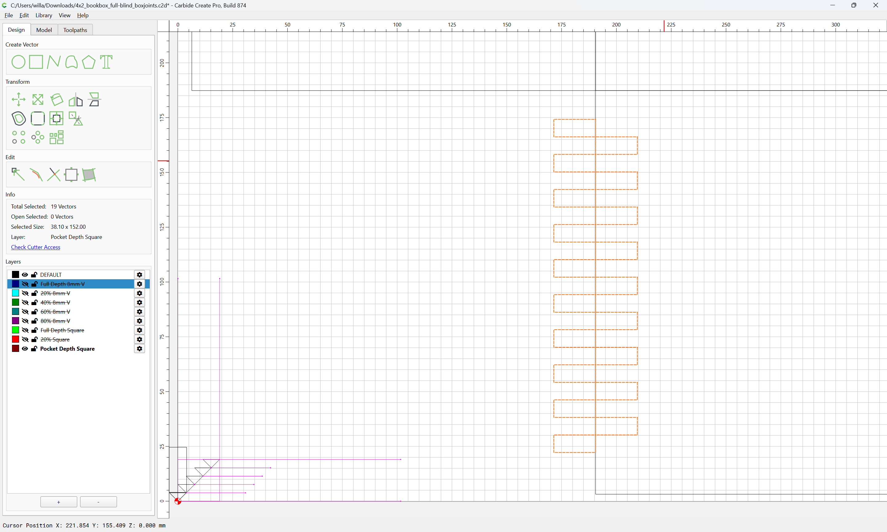
shift-click on the matching part outline to add it to the selection:
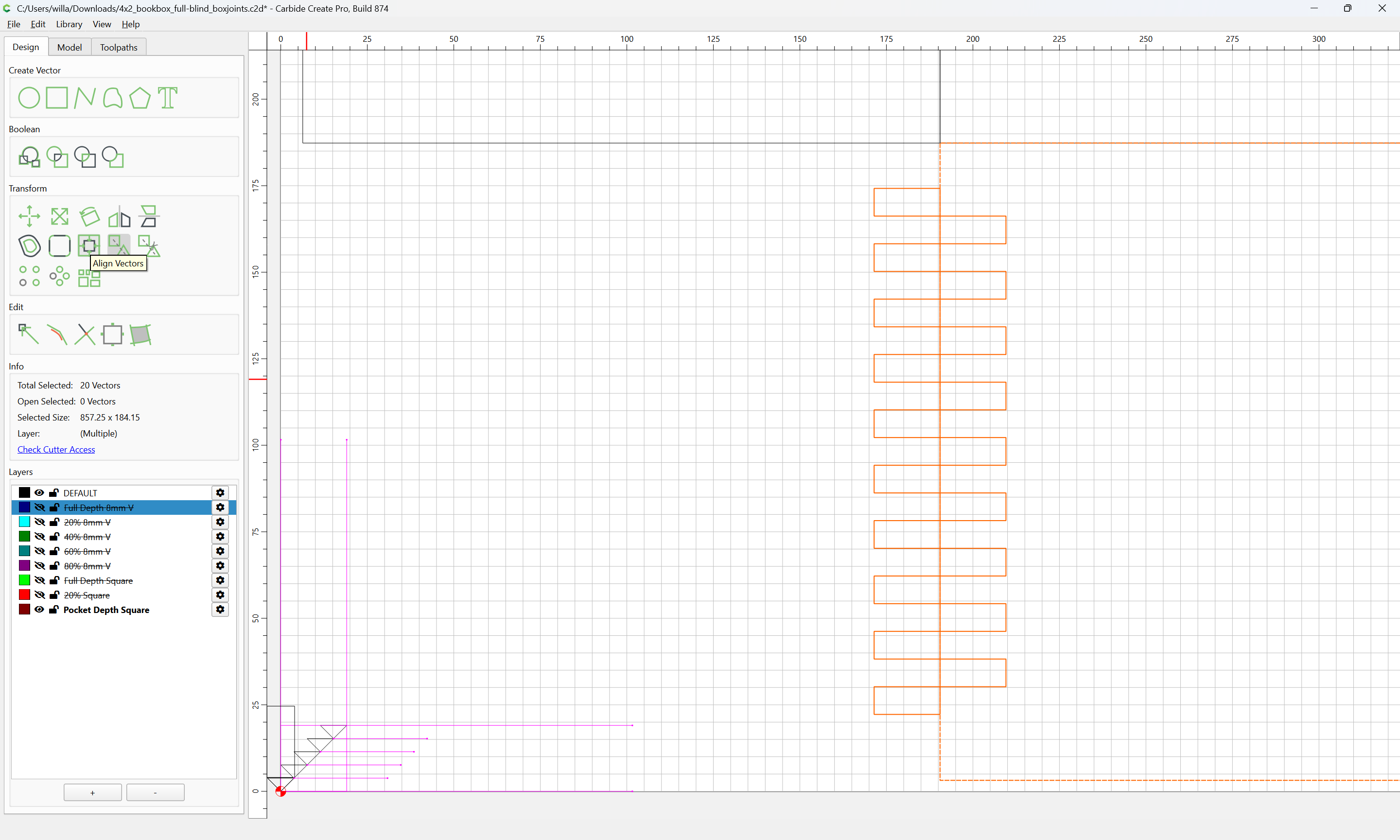
Align Vectors
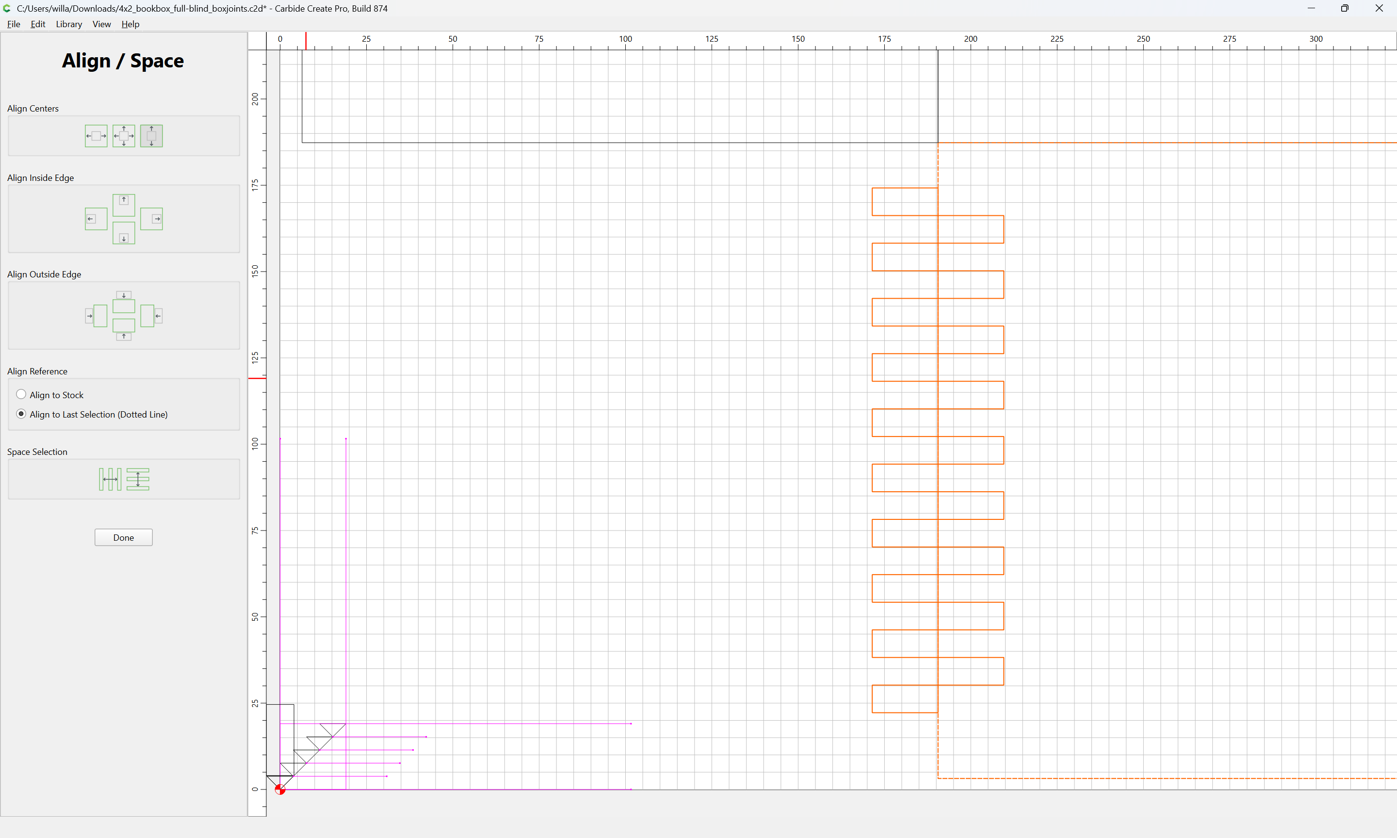
Align vertically

Done
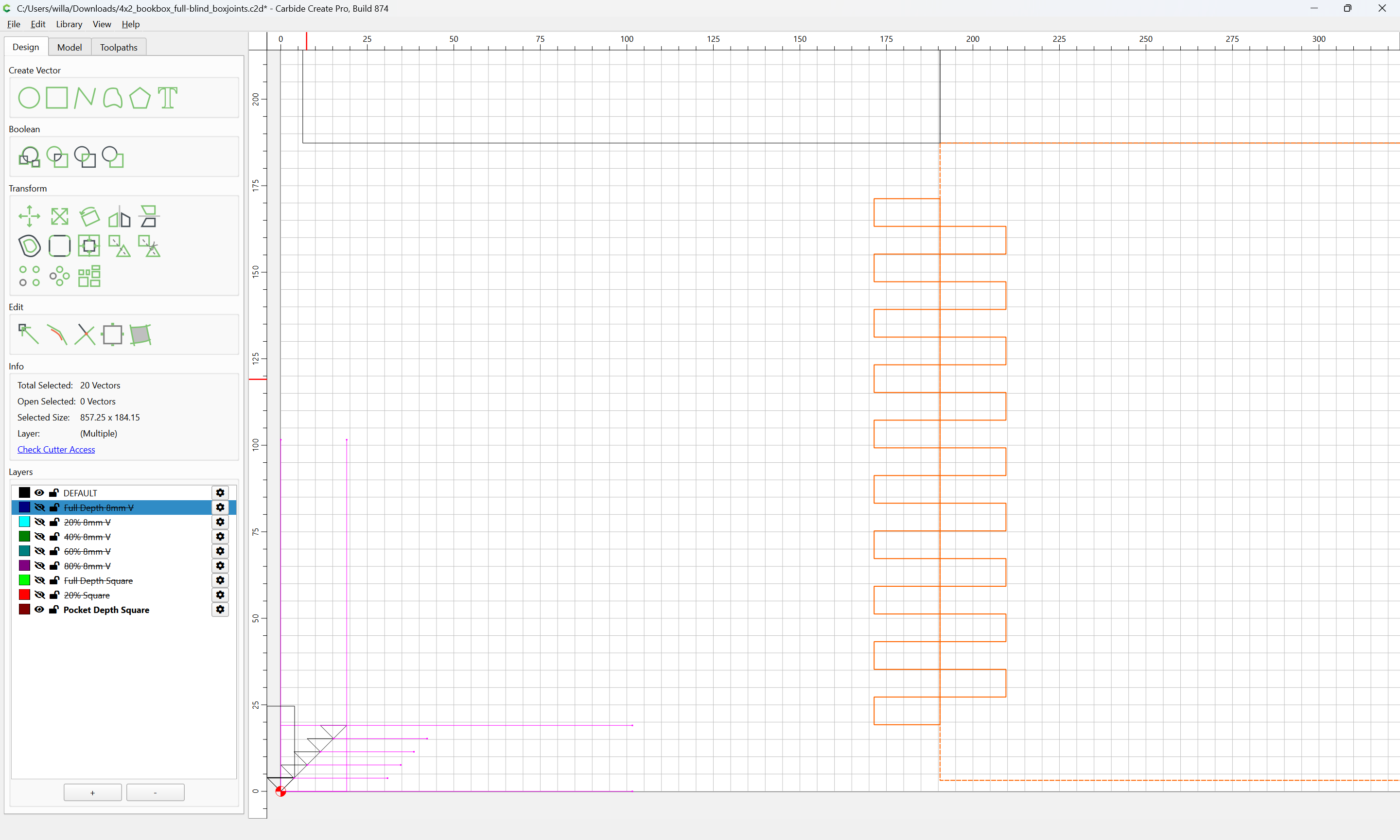
Because the toolpath will cut beyond where it begins/ends by tool radius the array should be reduced in width by the tool diameter:
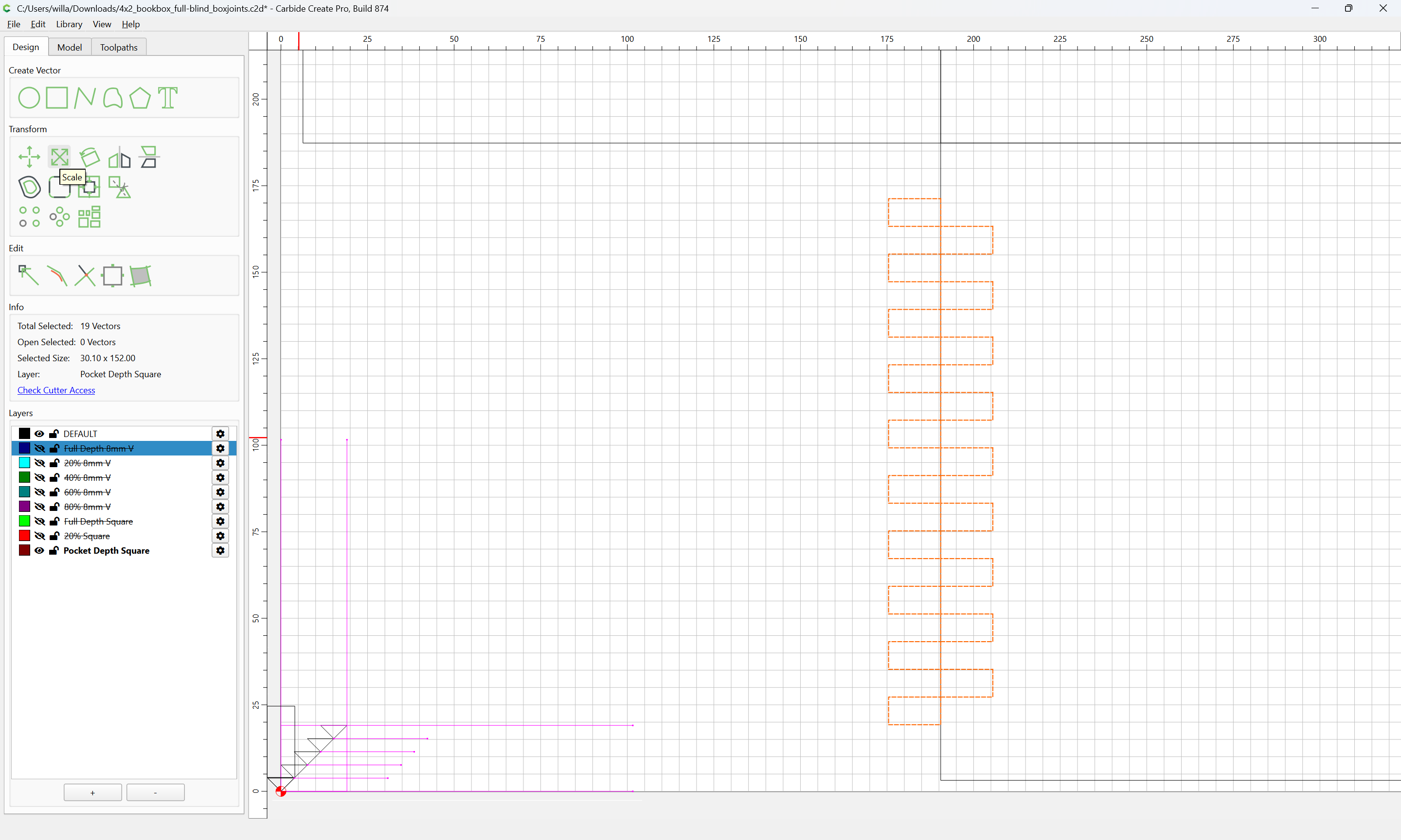
Scale
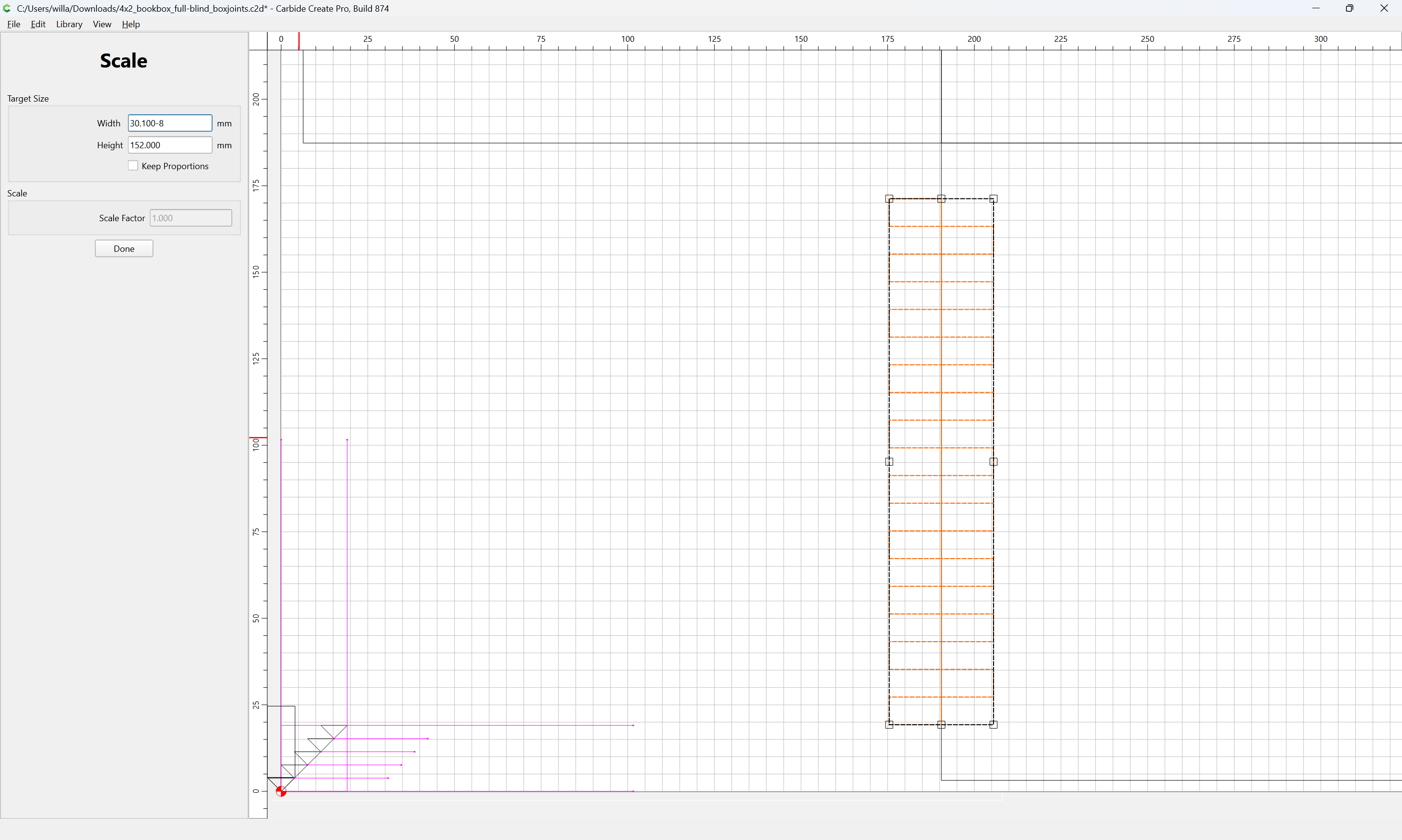
Done
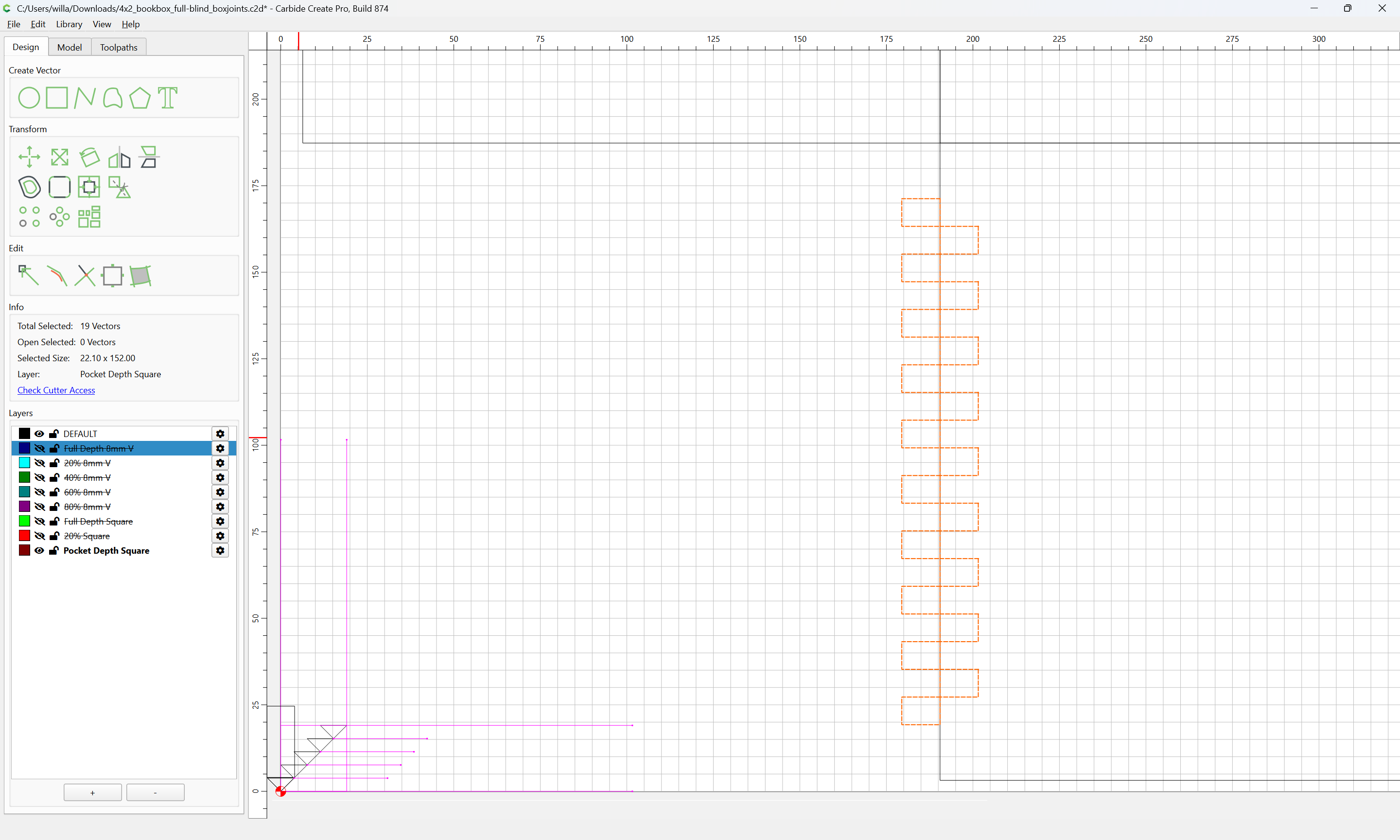
Draw a polyline for the toolpath which starts at the bottom edge of the part:
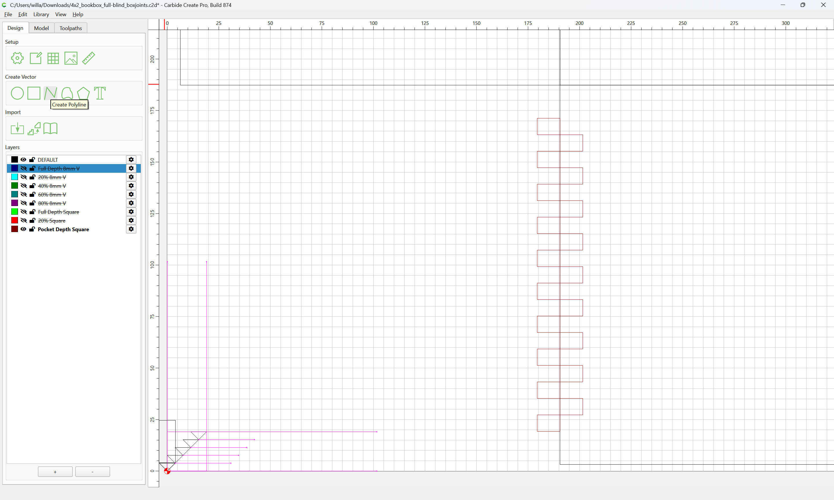
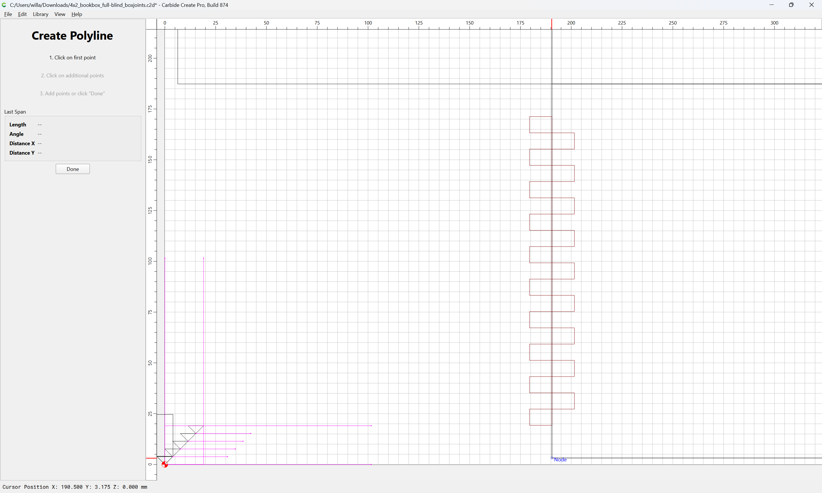
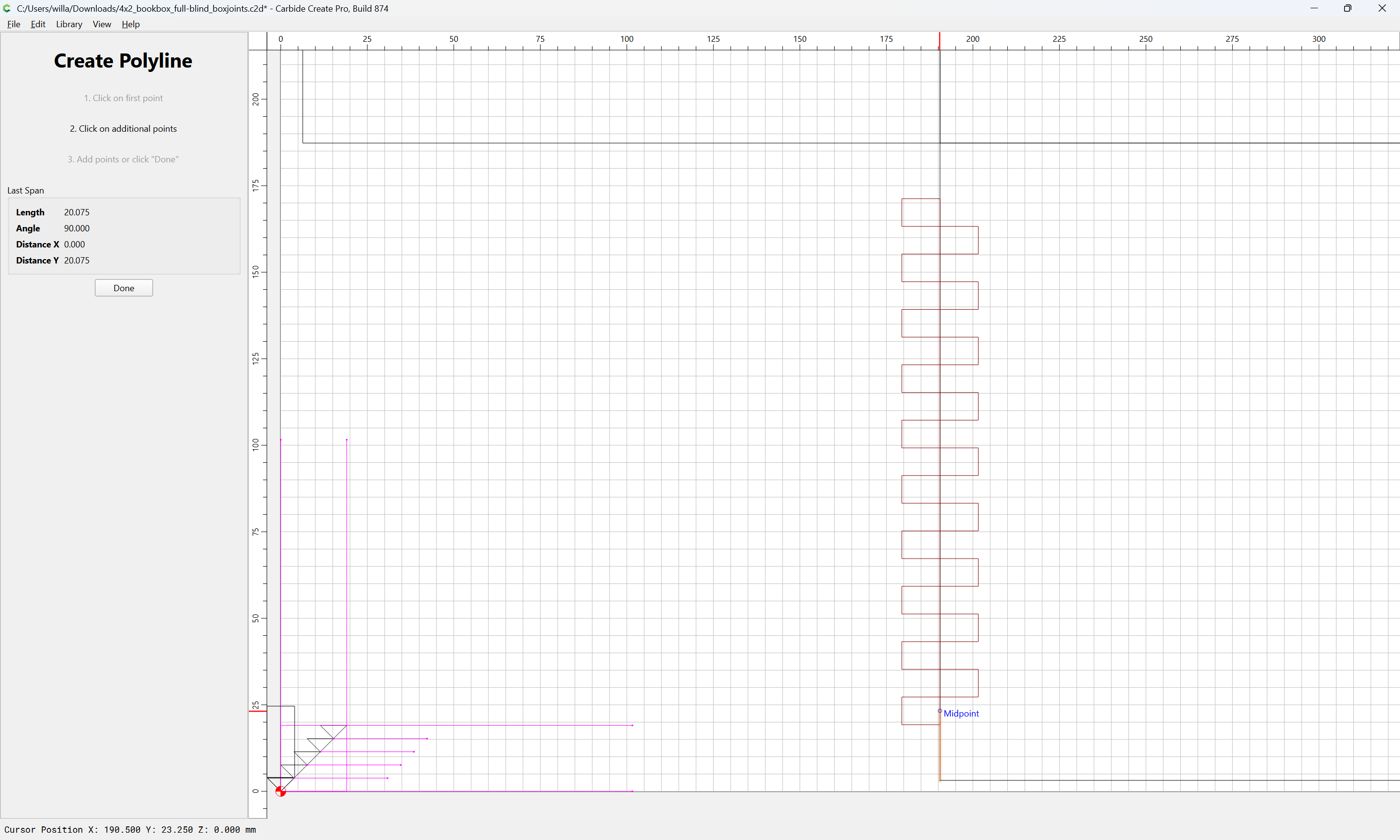
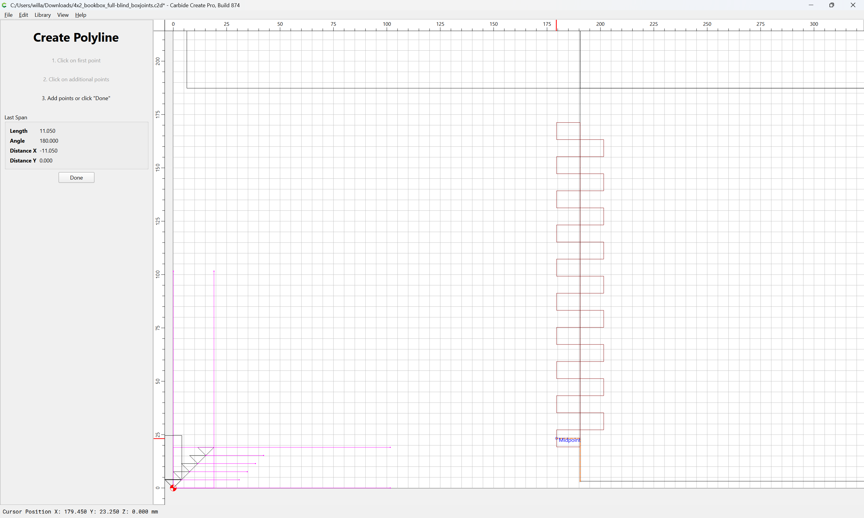
going back and forth
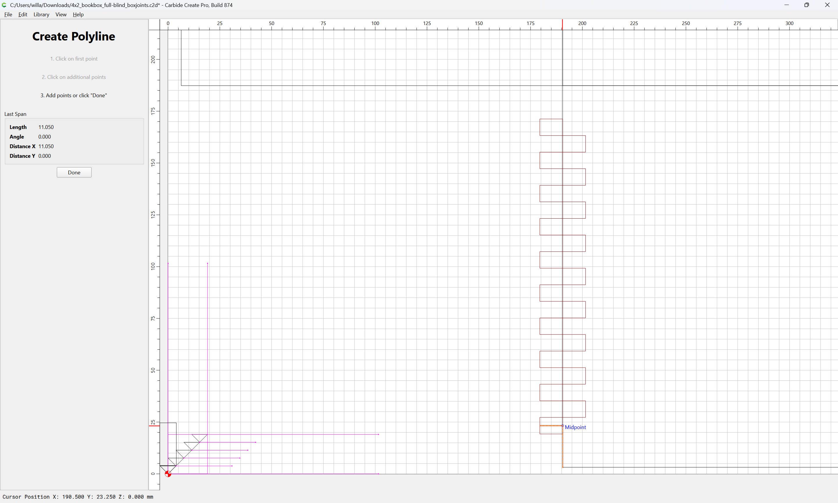
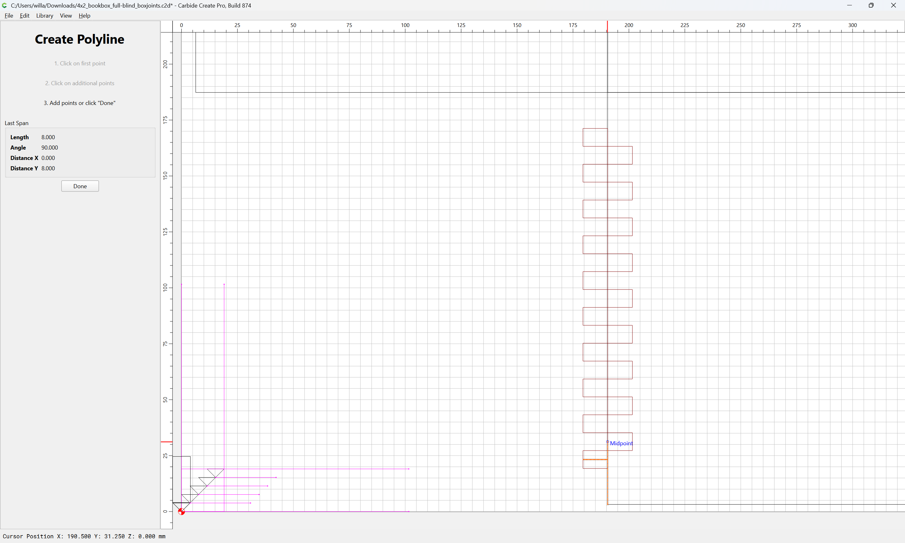
until one arrives at:

Done
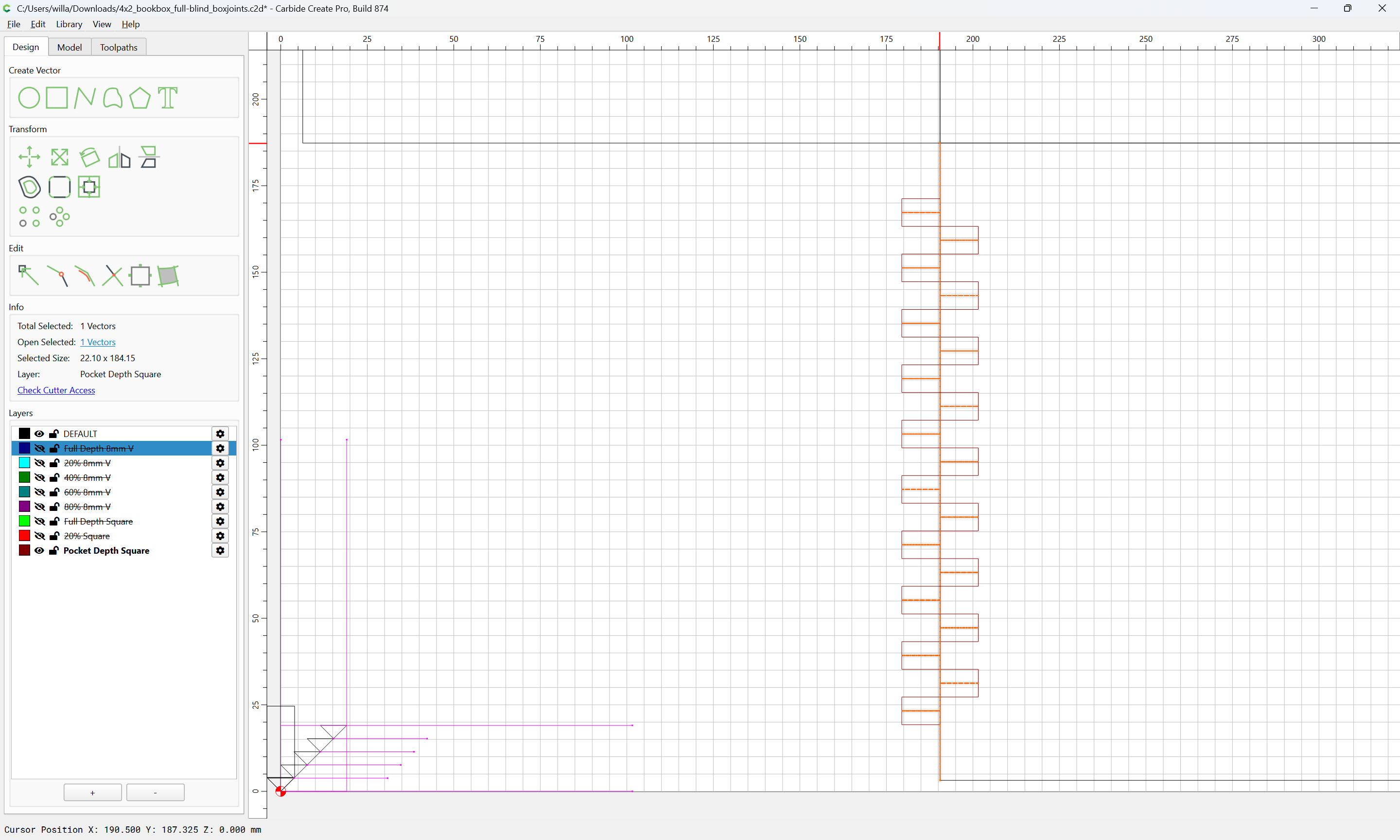
The linear array may then be deleted:
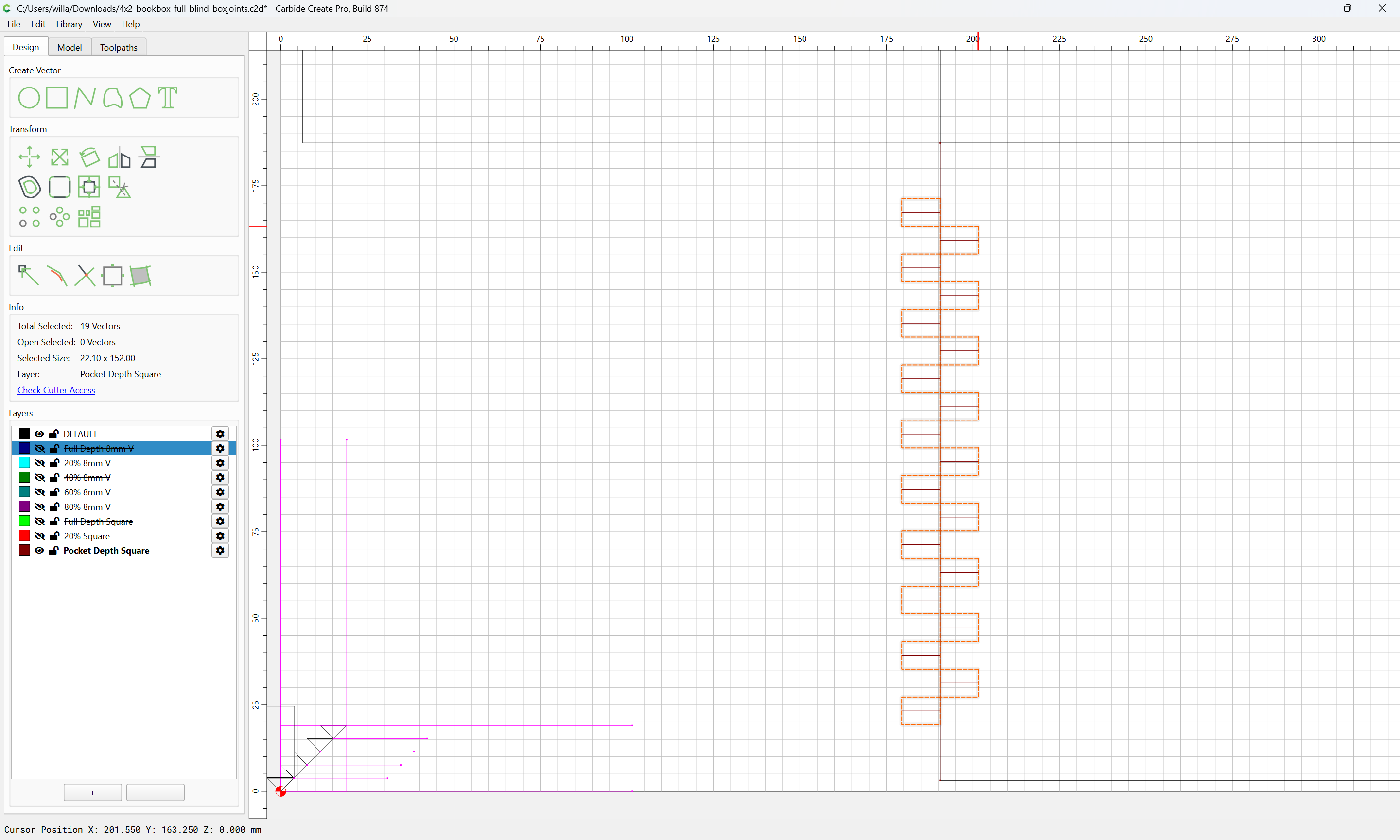
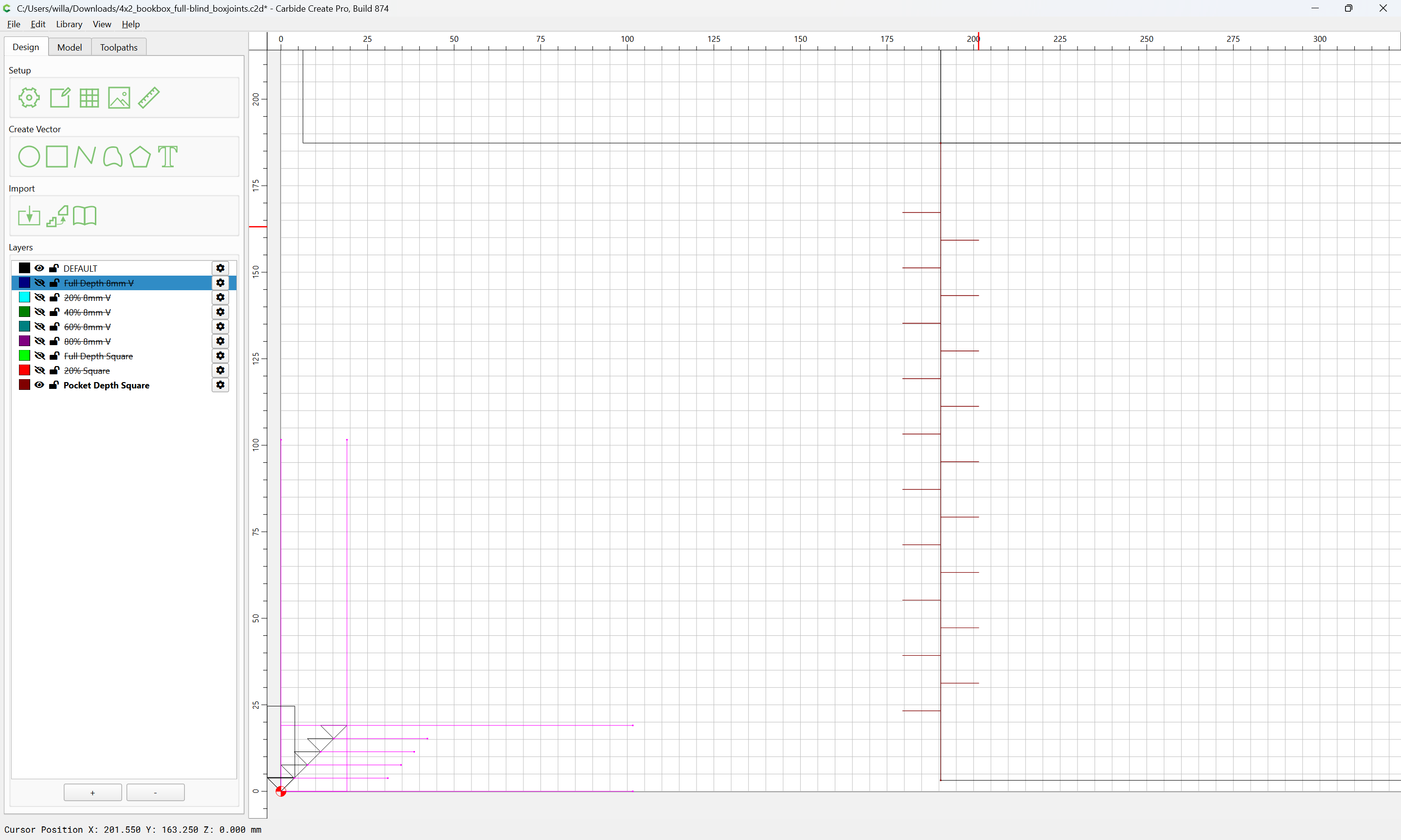
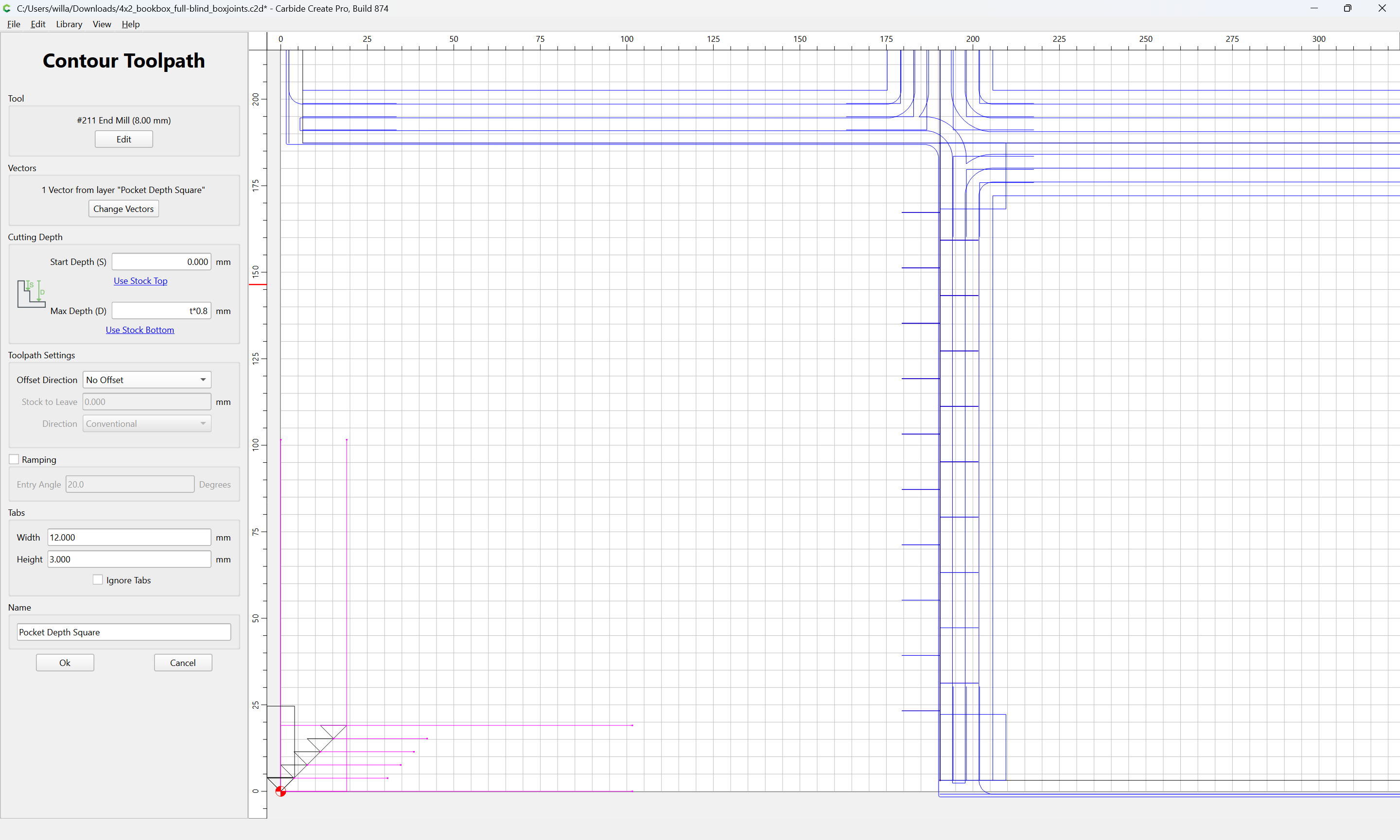
With a suitable toolpath applied to this layer:
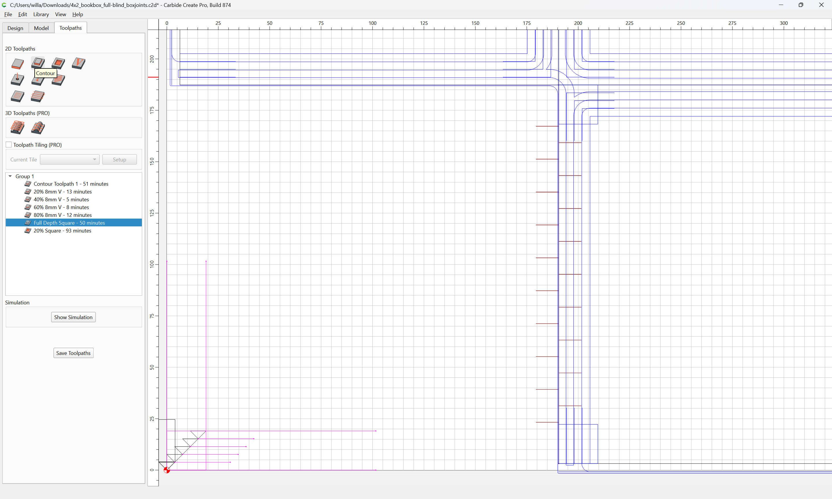
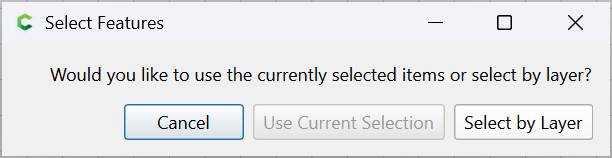
Select by Layer
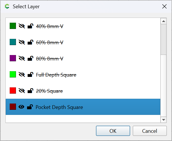
OK
it previews as:
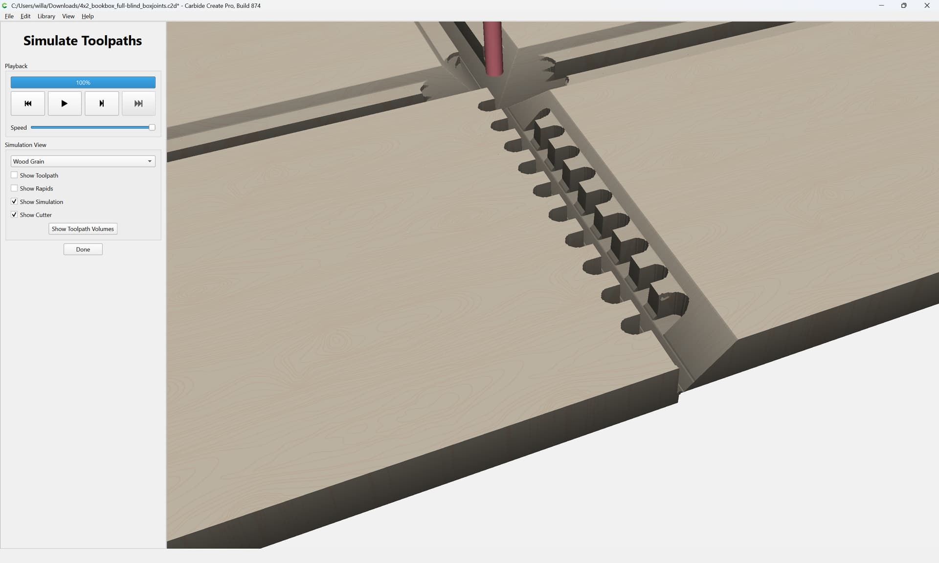
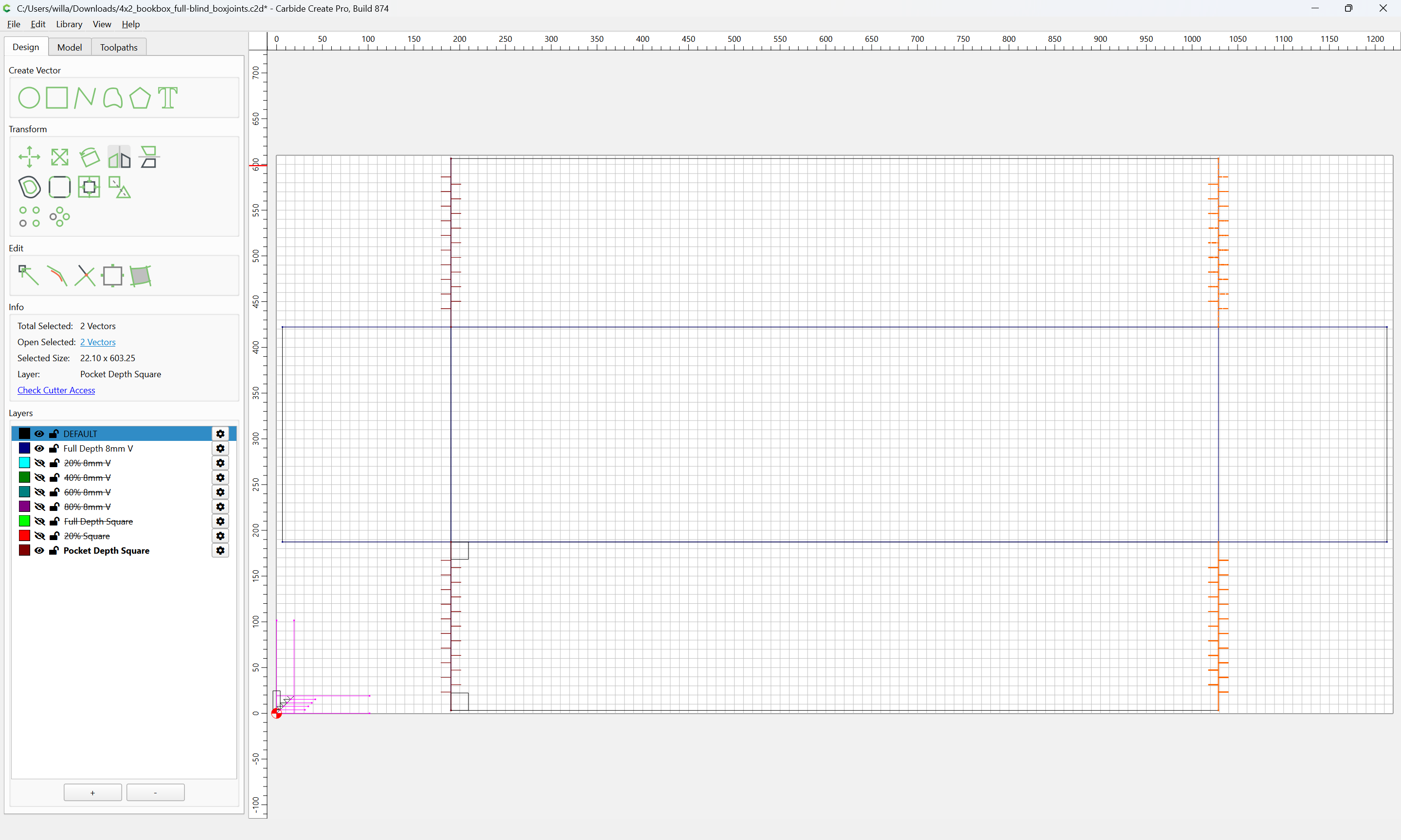
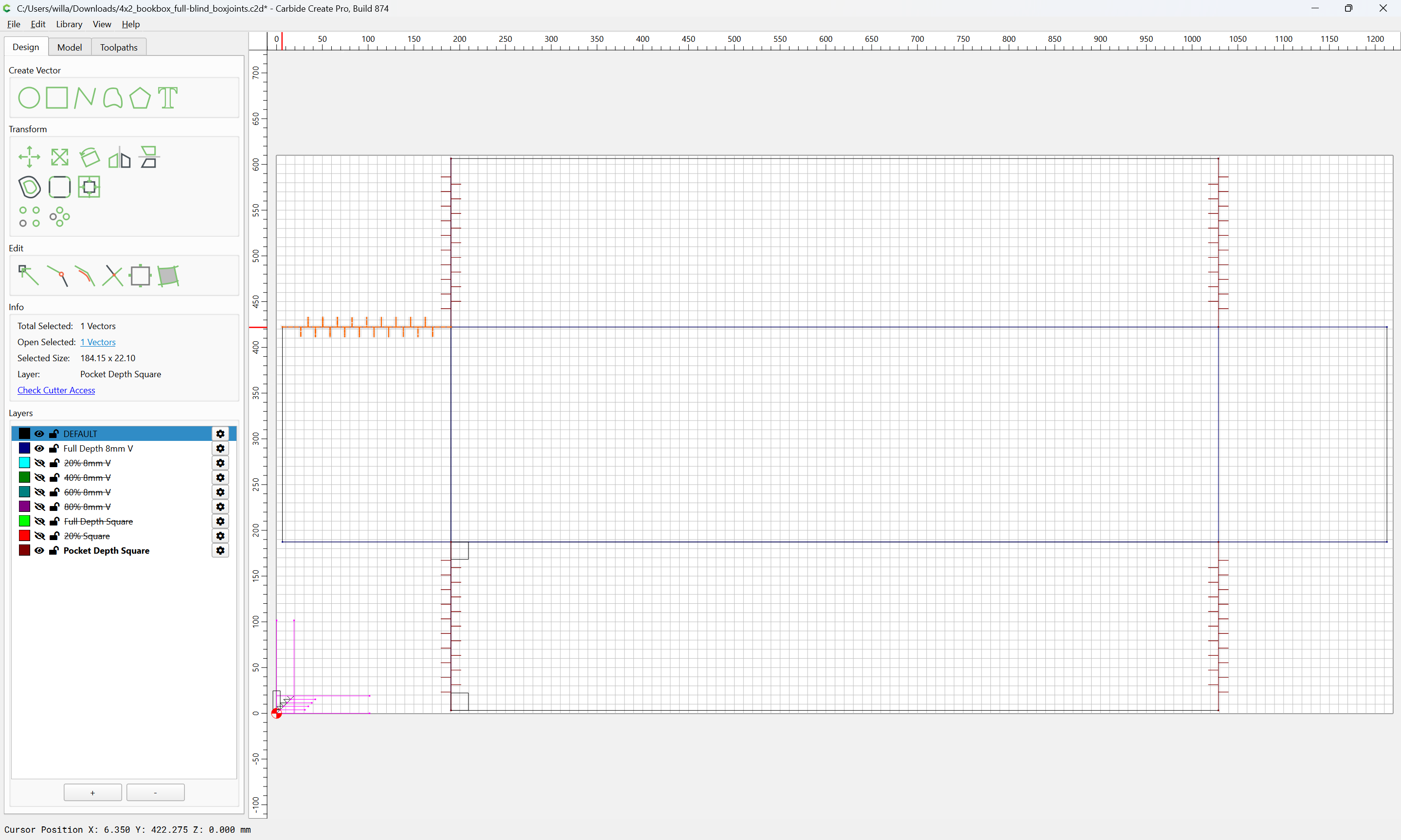
and may be duplicated and mirrored where appropriate:
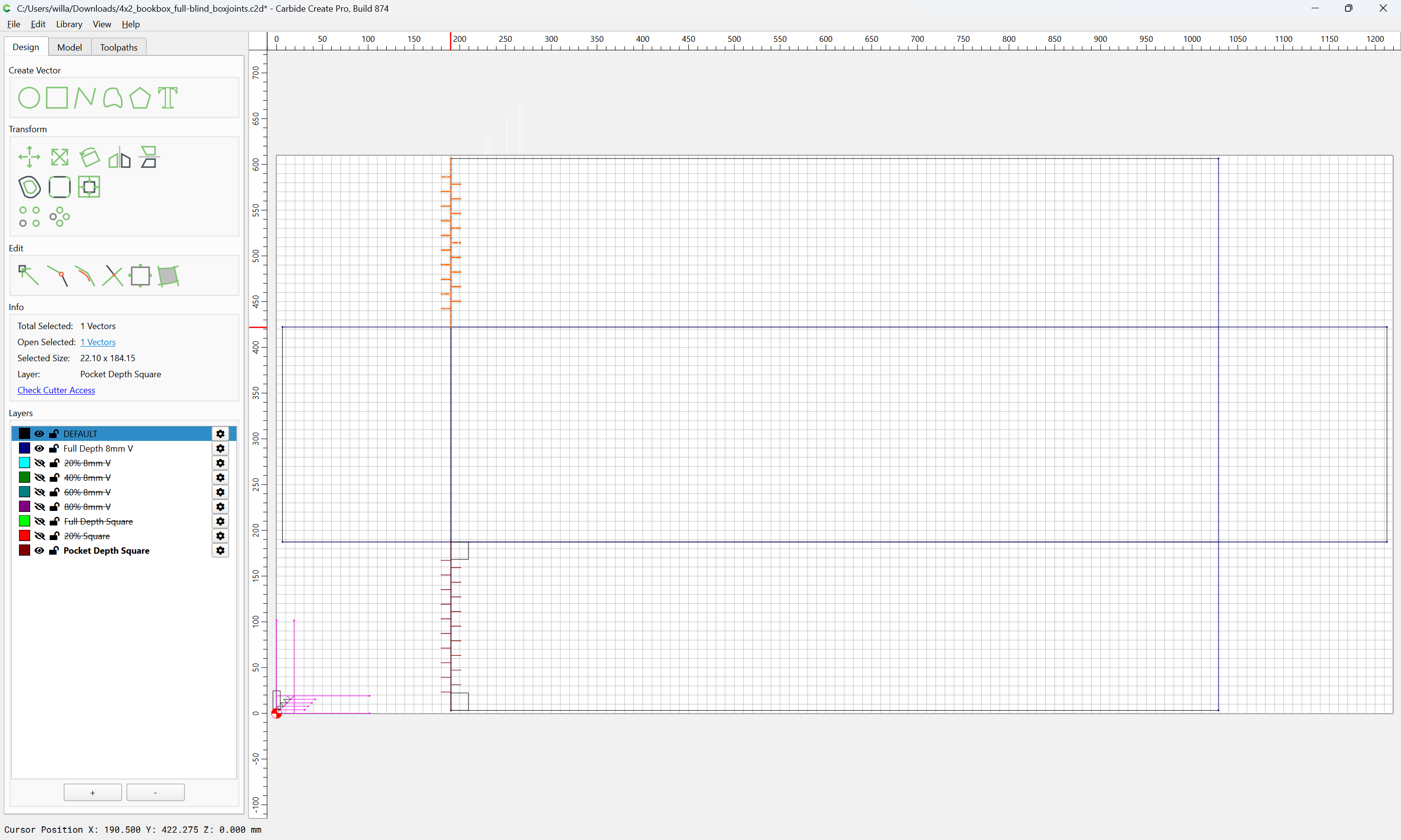
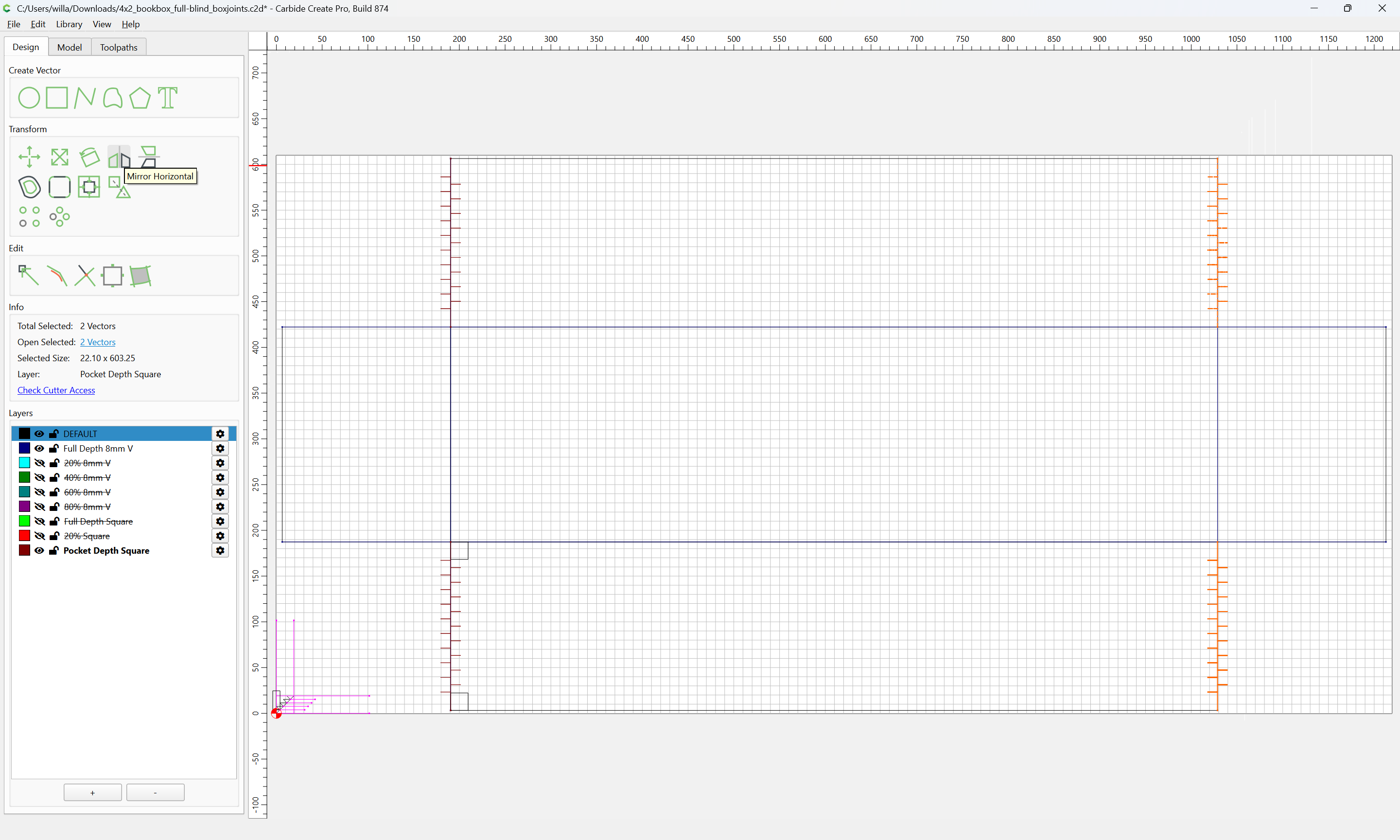
Mirror Horizontal
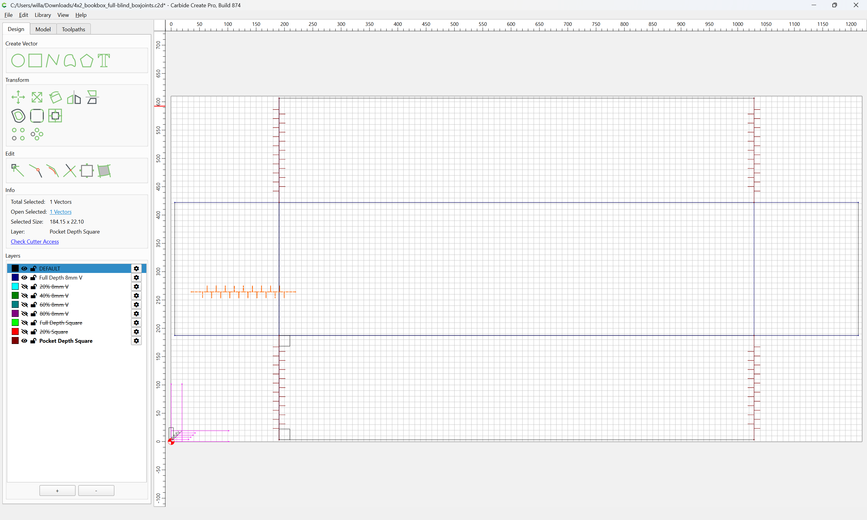
and also rotated:
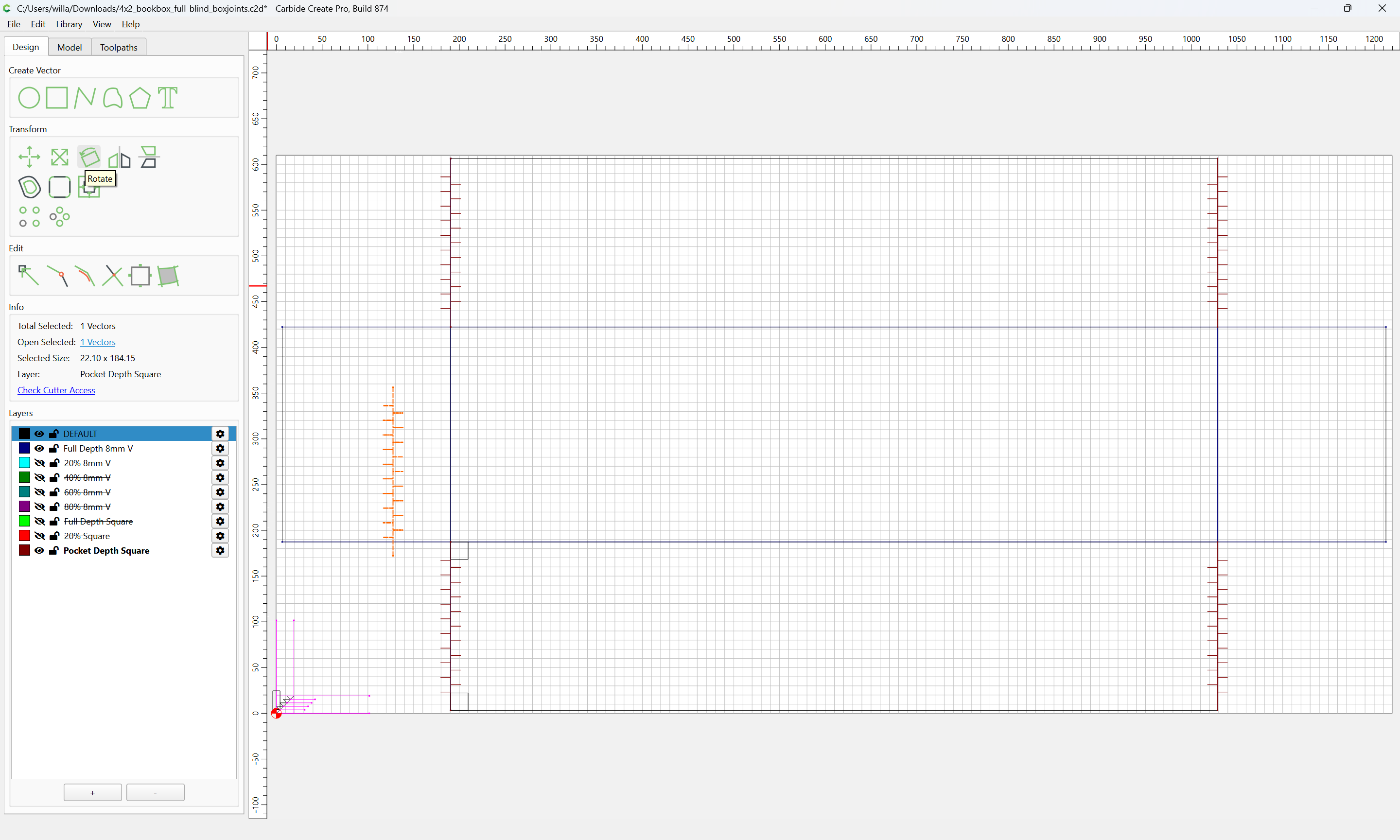
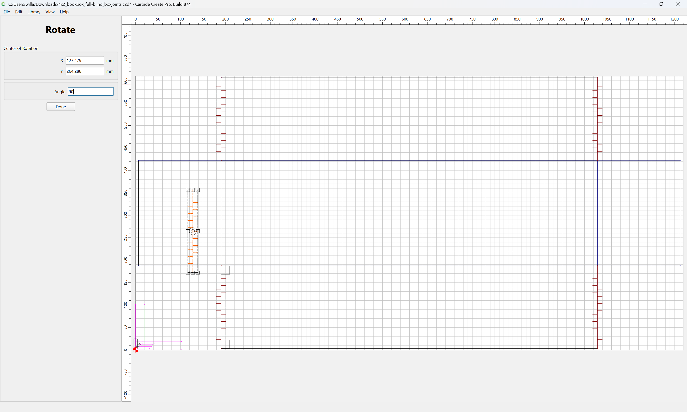
Done
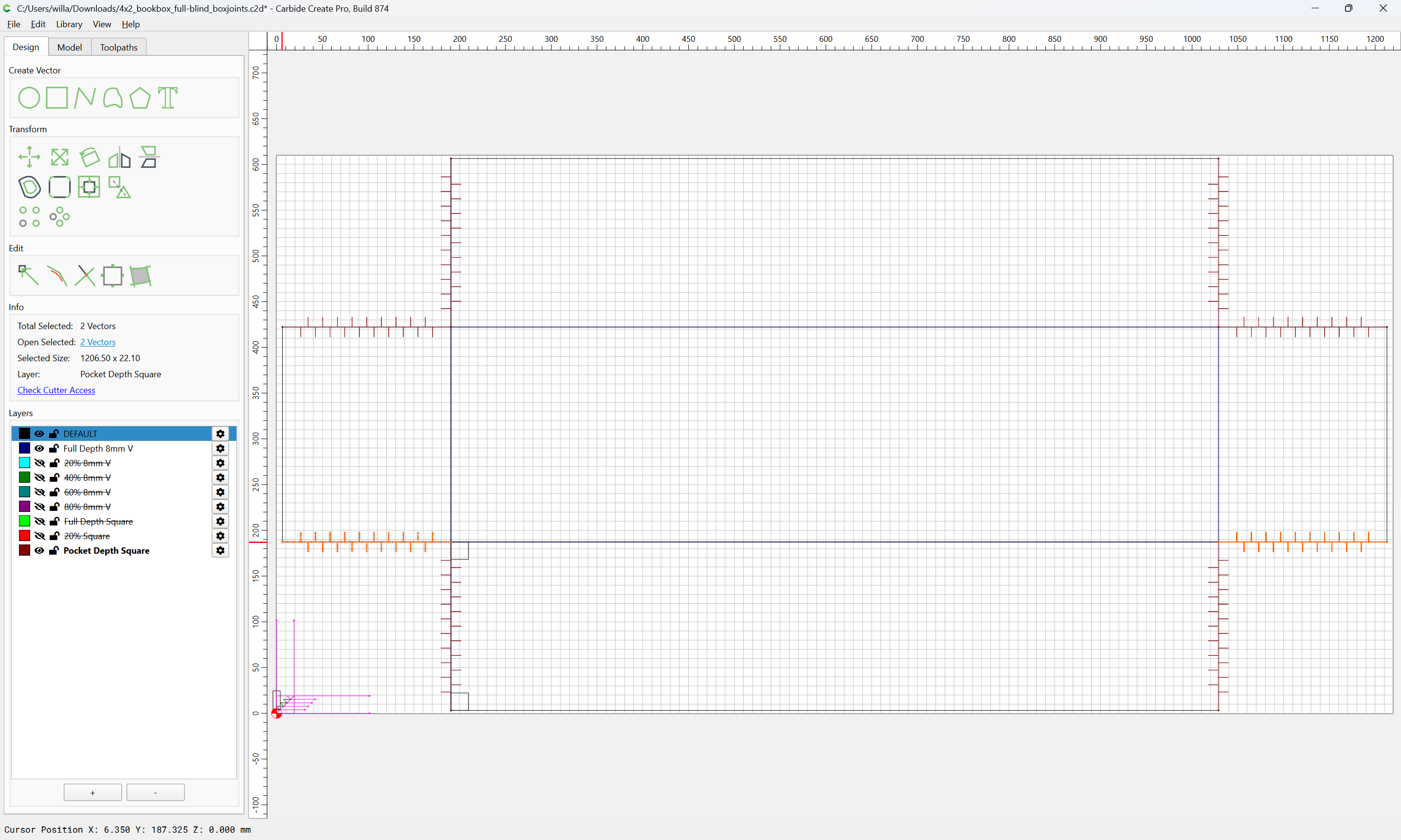
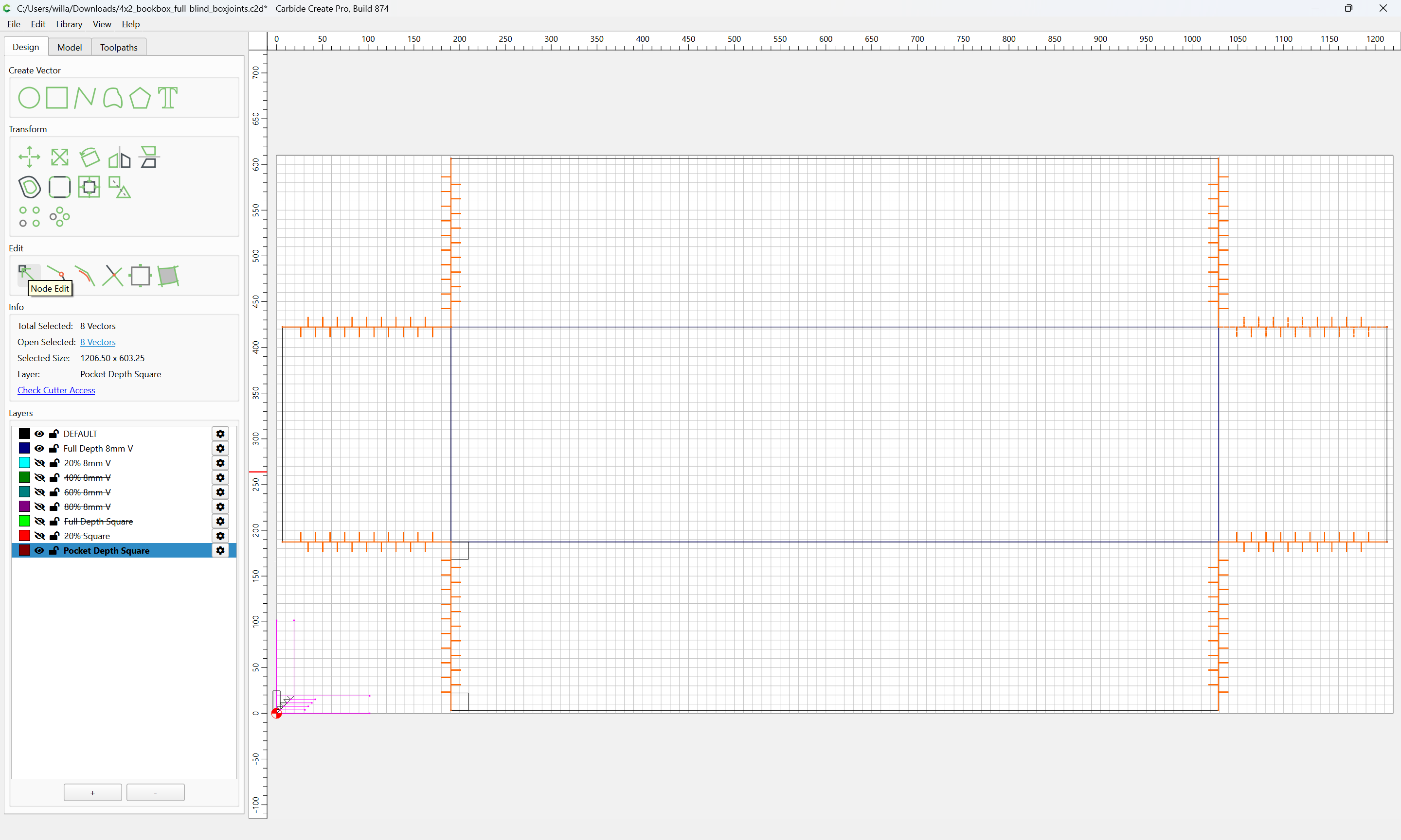
Select all on the Pocket Depth layer:
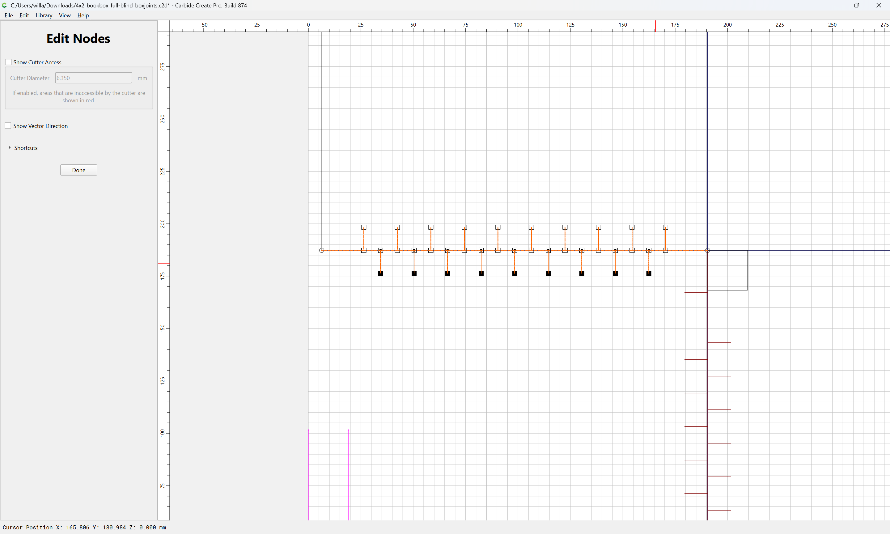
and use Node Editing to remove the unneeded lines:
d
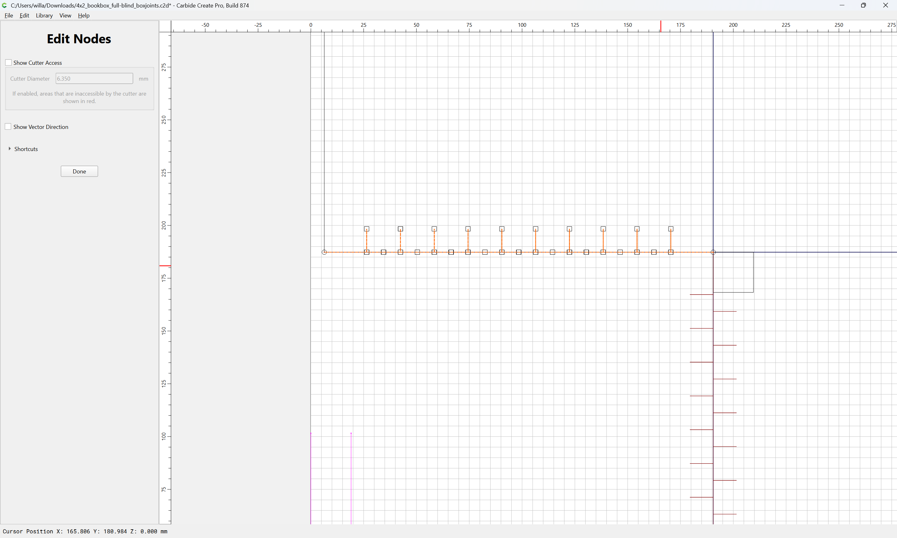
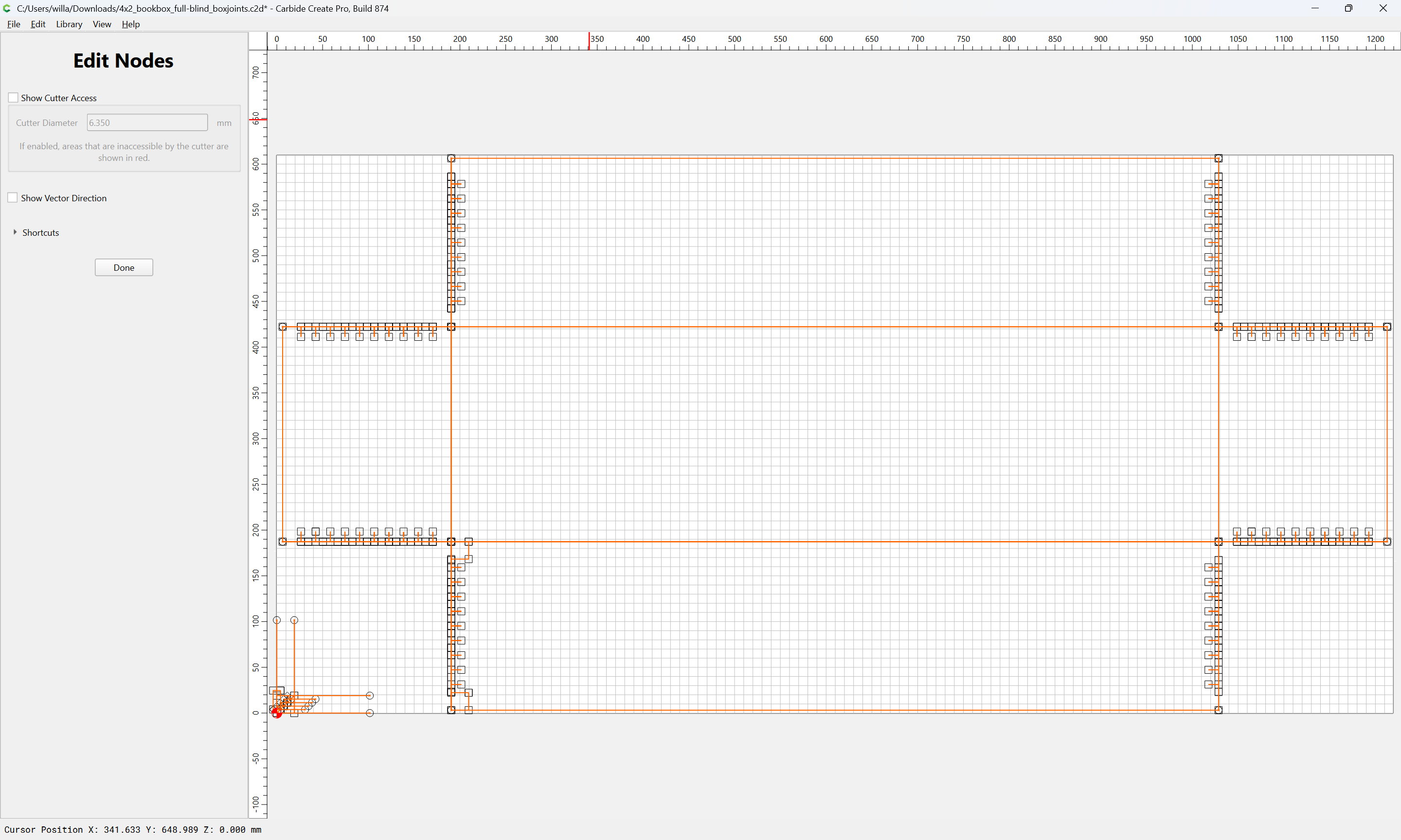
Repeat this for the other edges where joints are needed.
1 Like
My dude… woah!!! This example u just cooked up for me is gold! I’ll be working thru this for the next week man. Thank u!
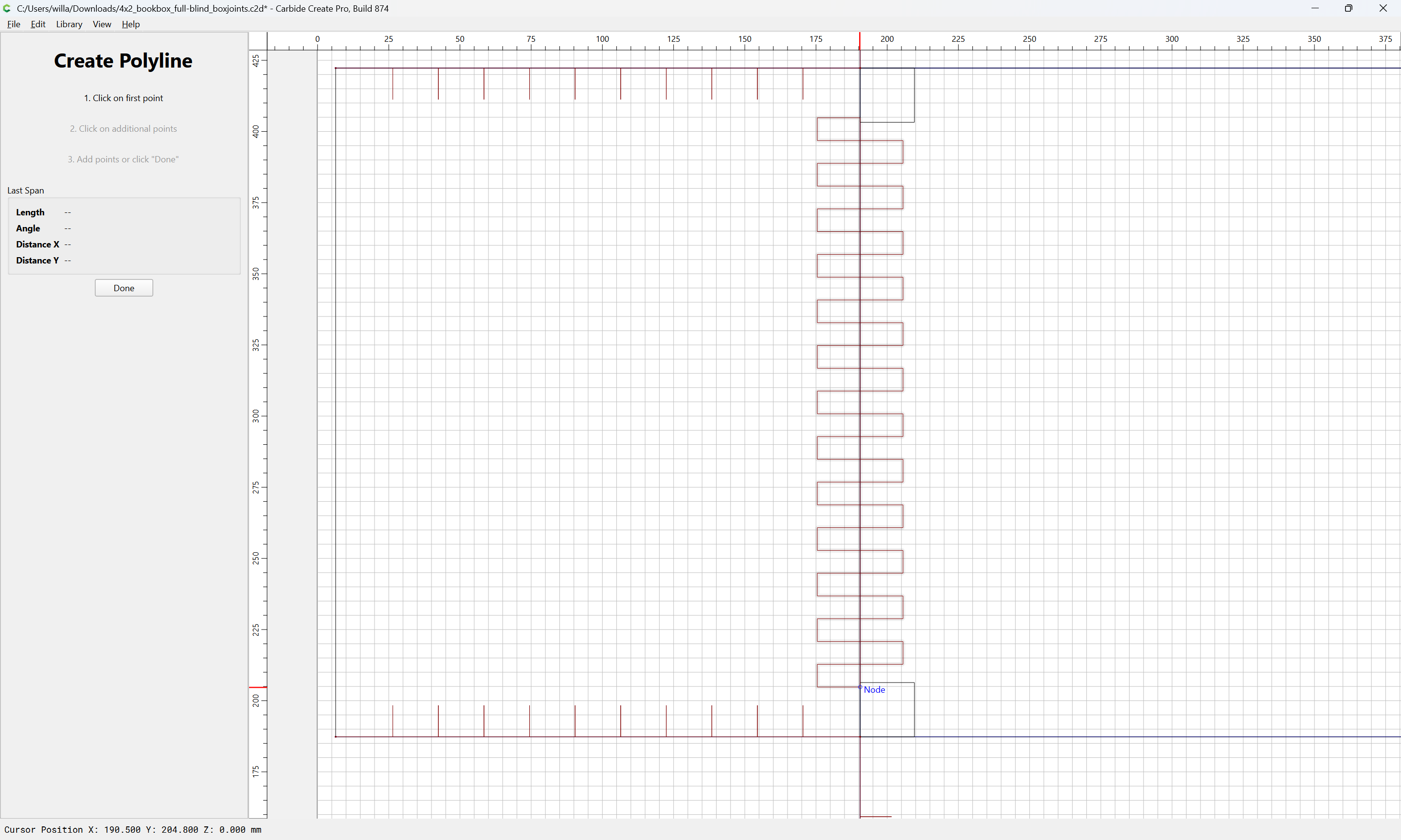
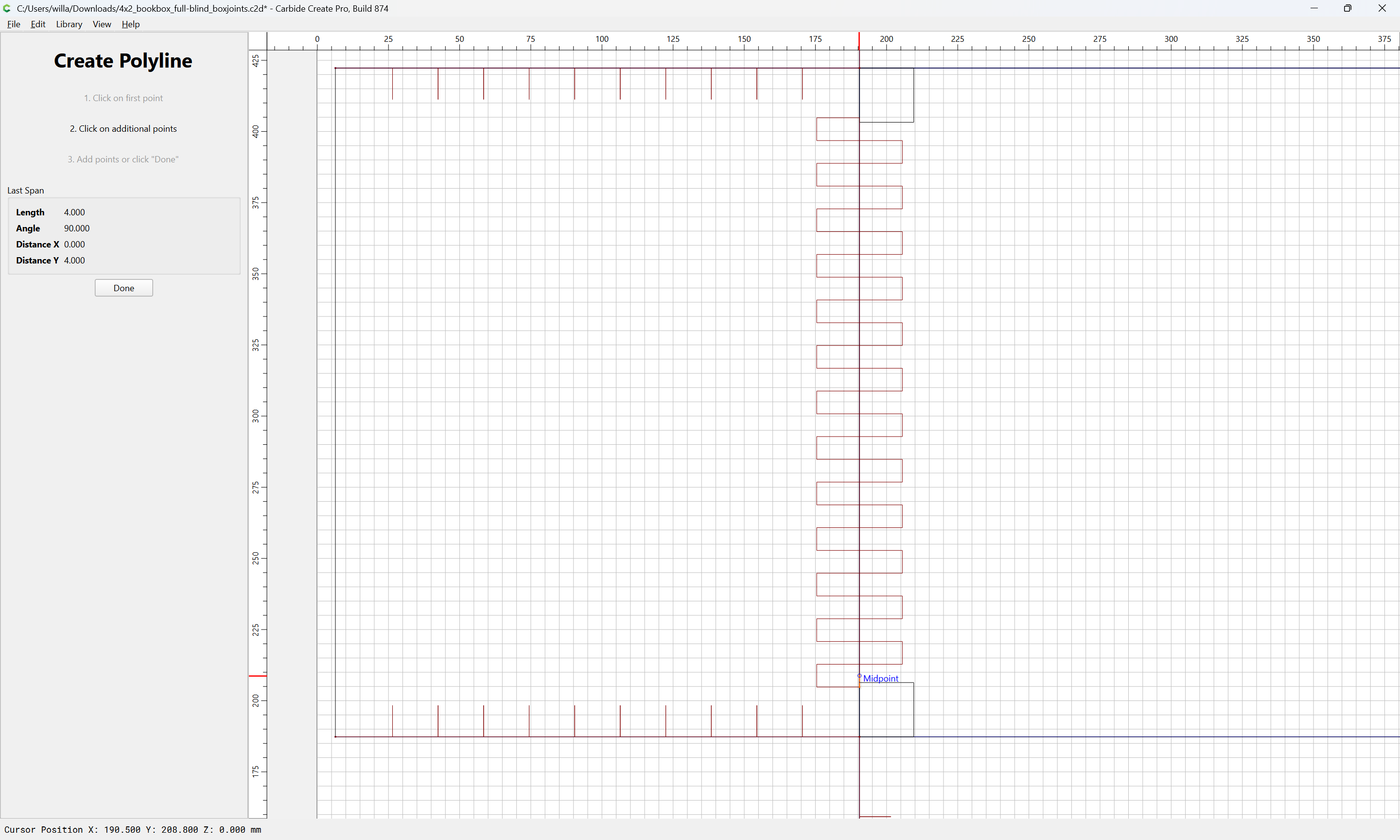
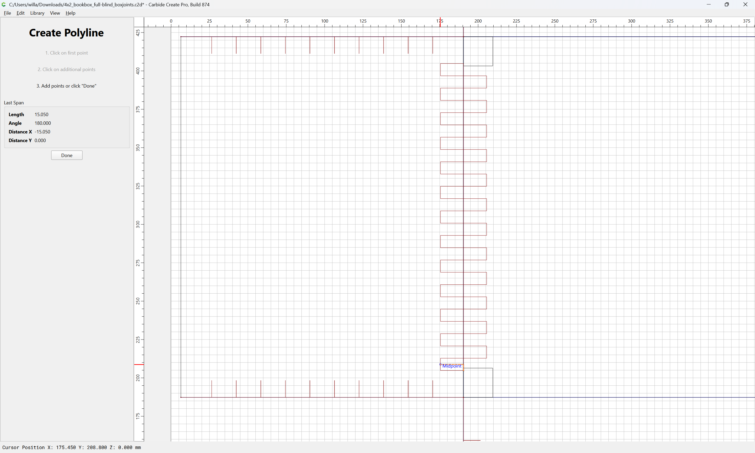
An alternative approach would be to position the rectangles which show where the joinery will be cut:

Draw one pair of joinery cuts:
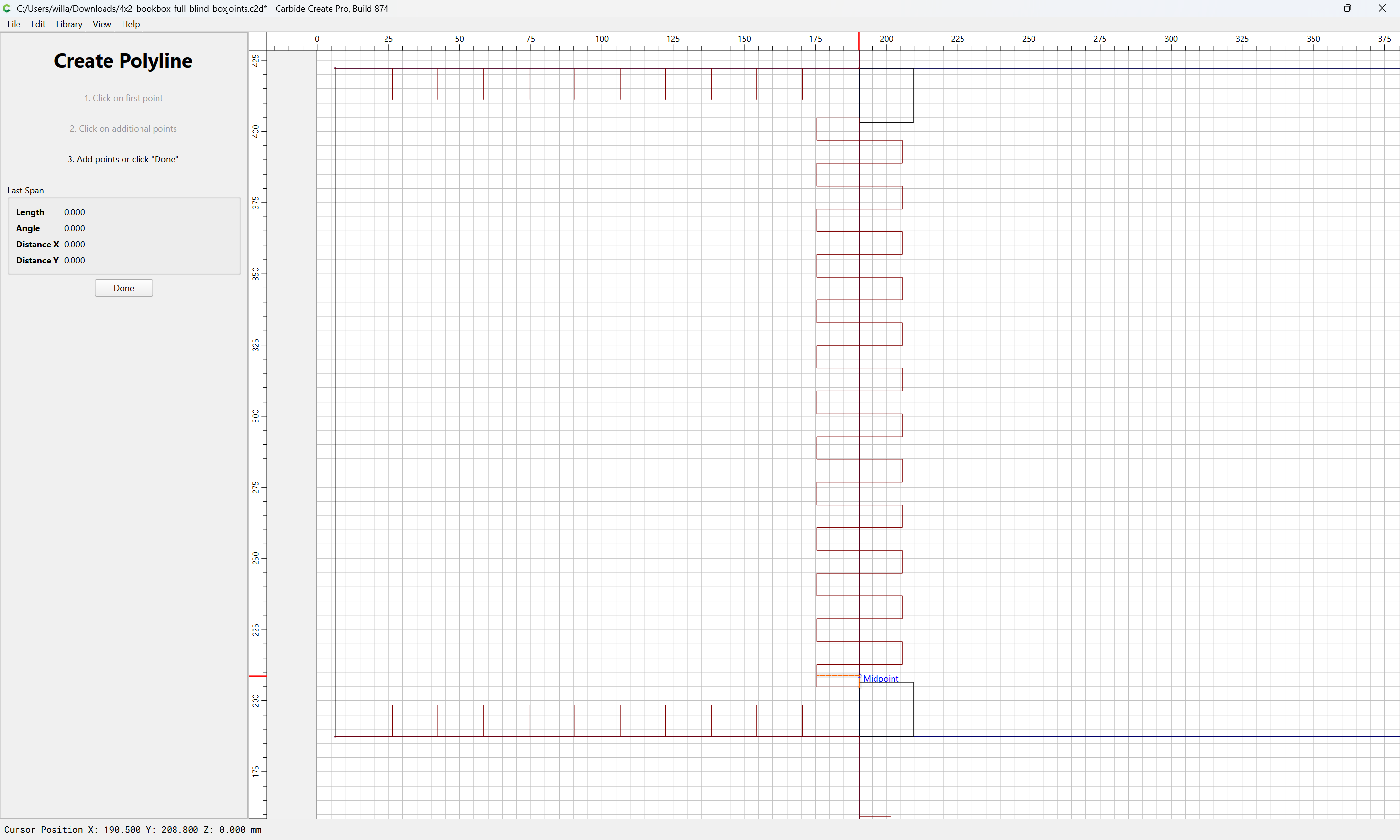
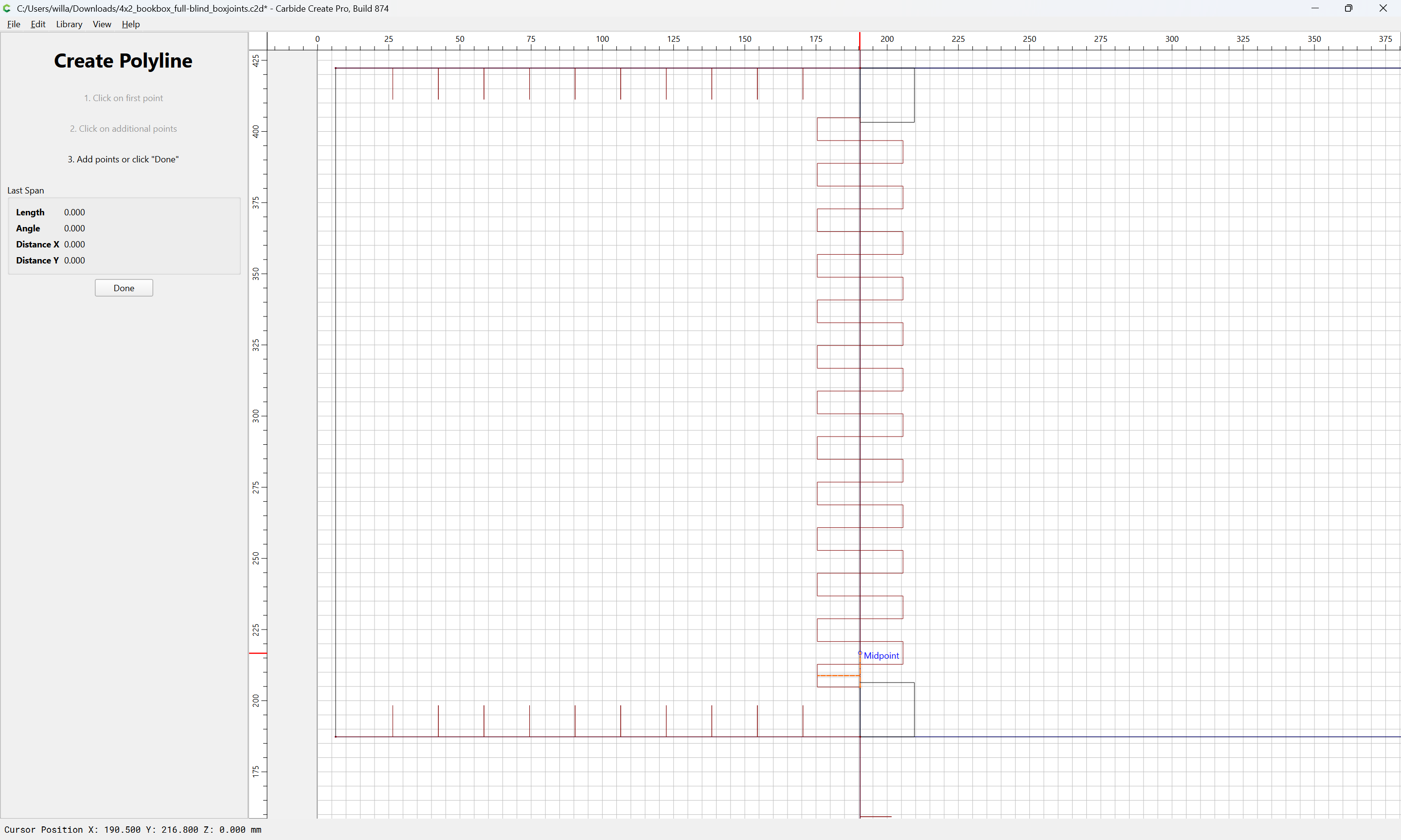

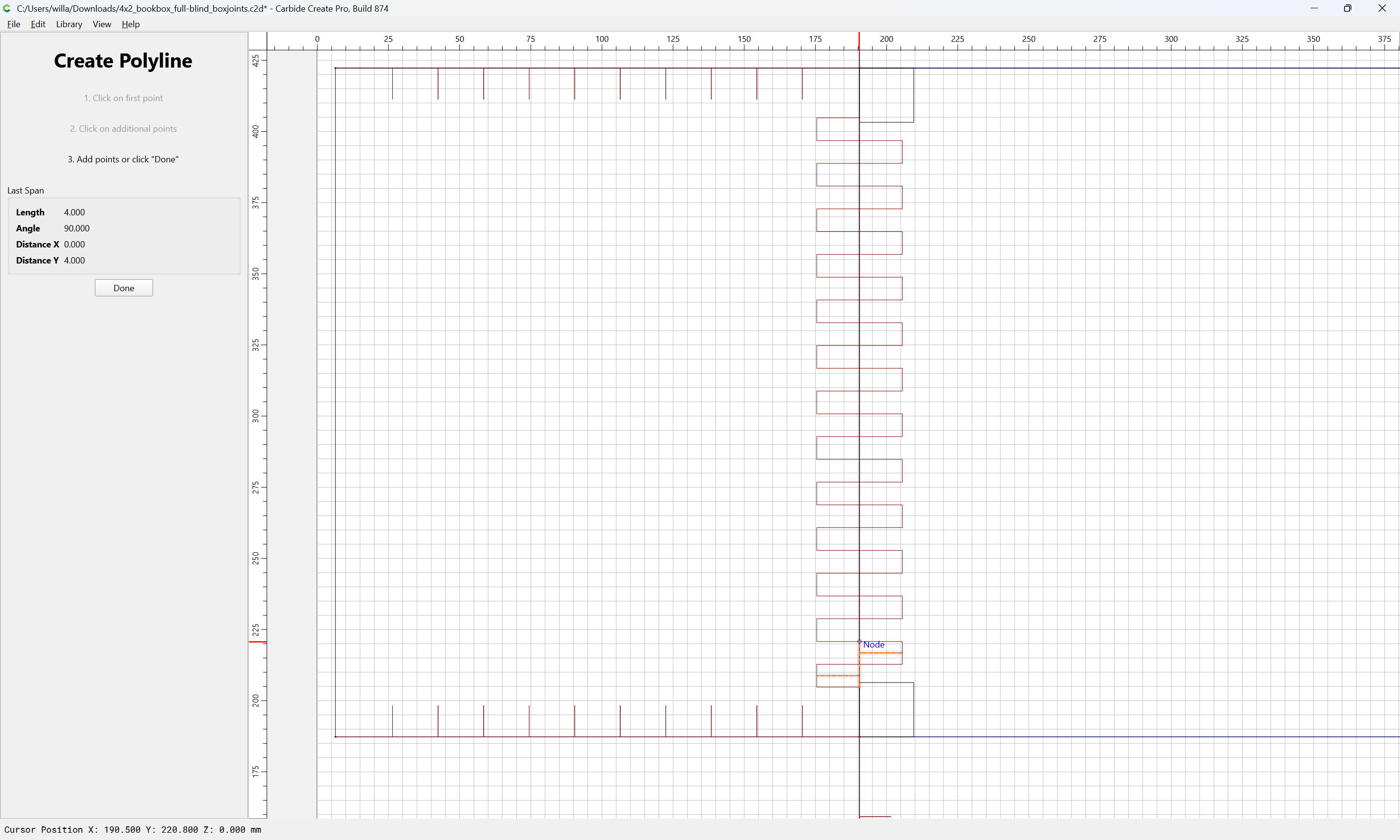
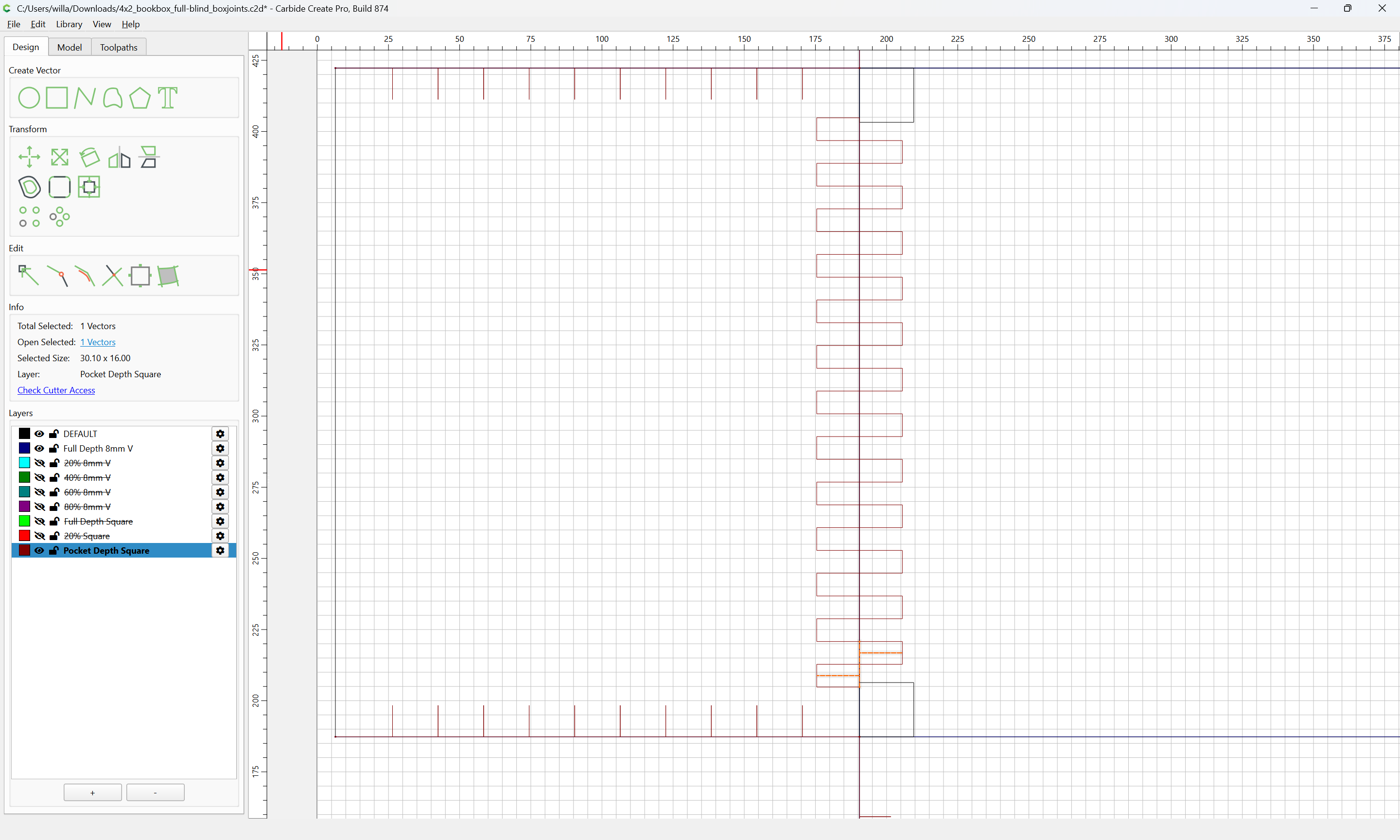
Done

and use Linear Array to duplicate just that:
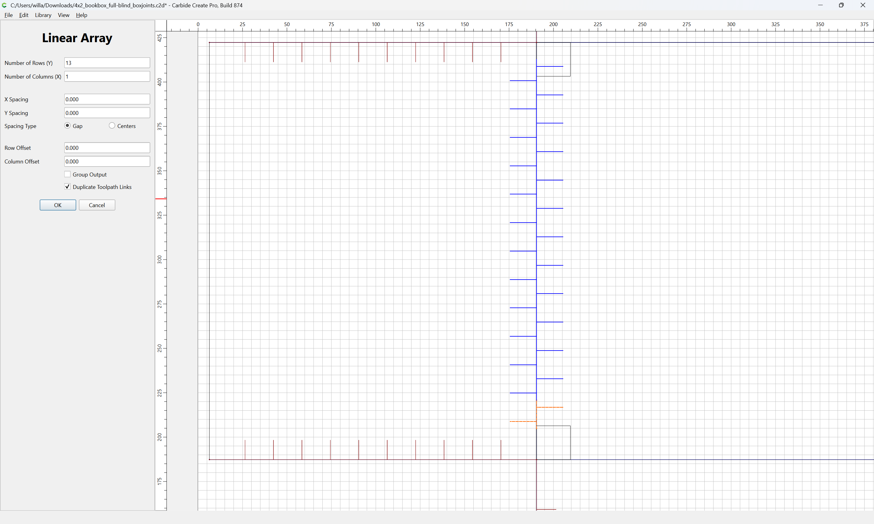
then node edit and clean up/extend the ends.
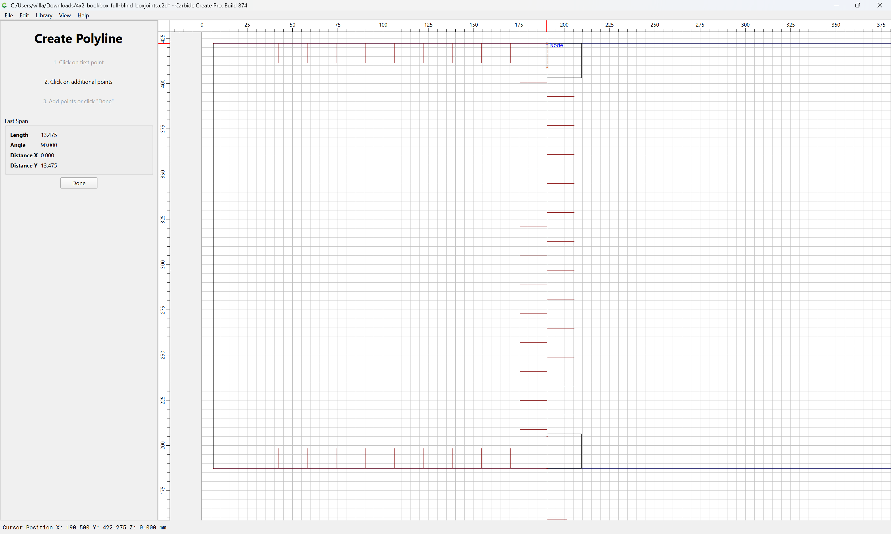
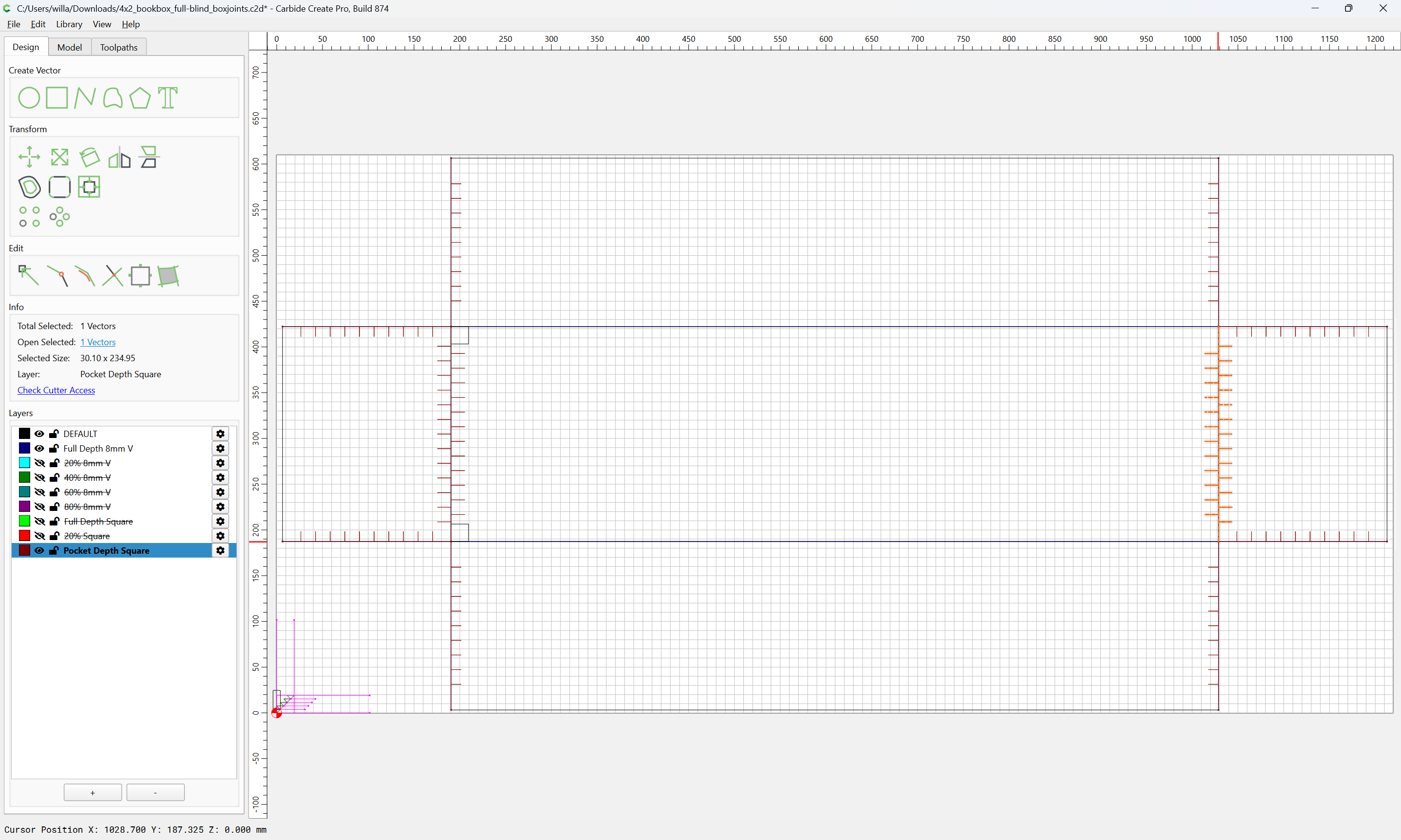
Probably this is pretty much required for the long edge:
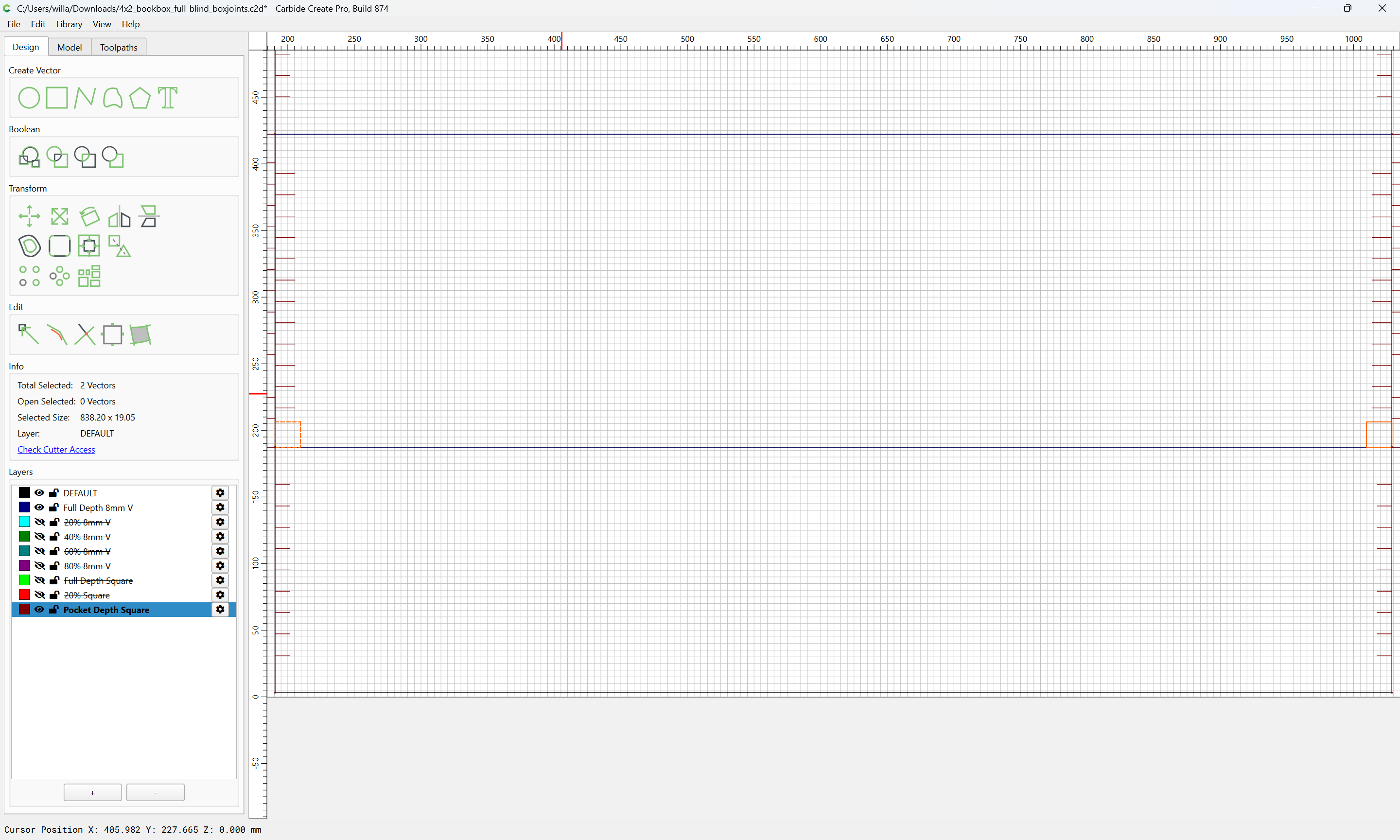
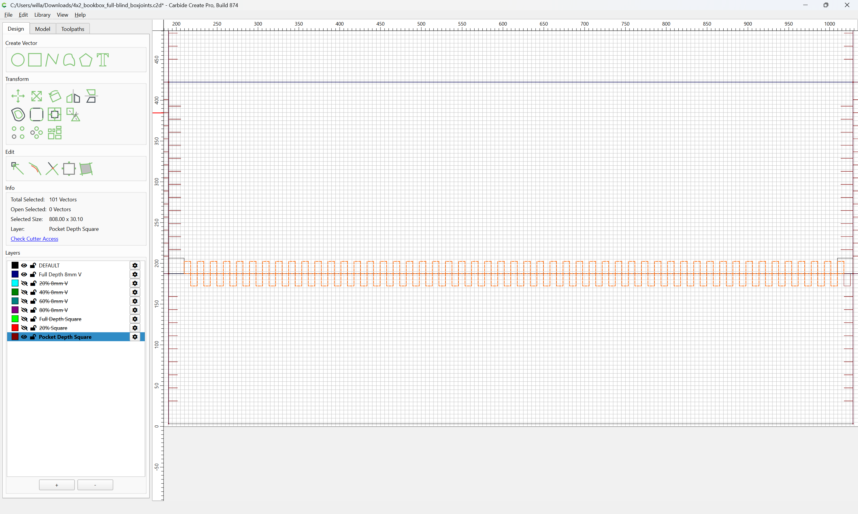

delete
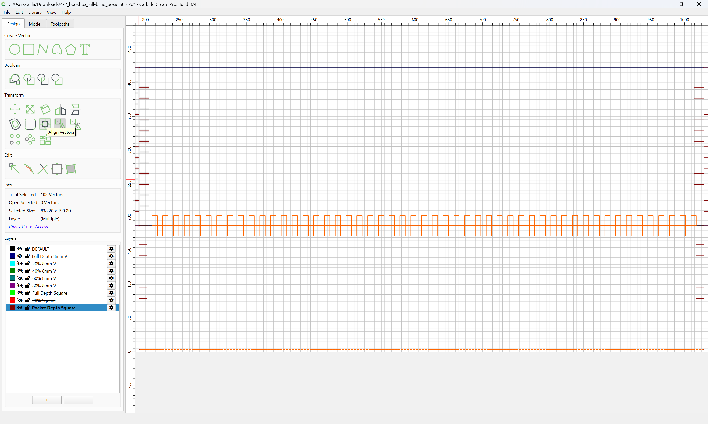
Align Vectors
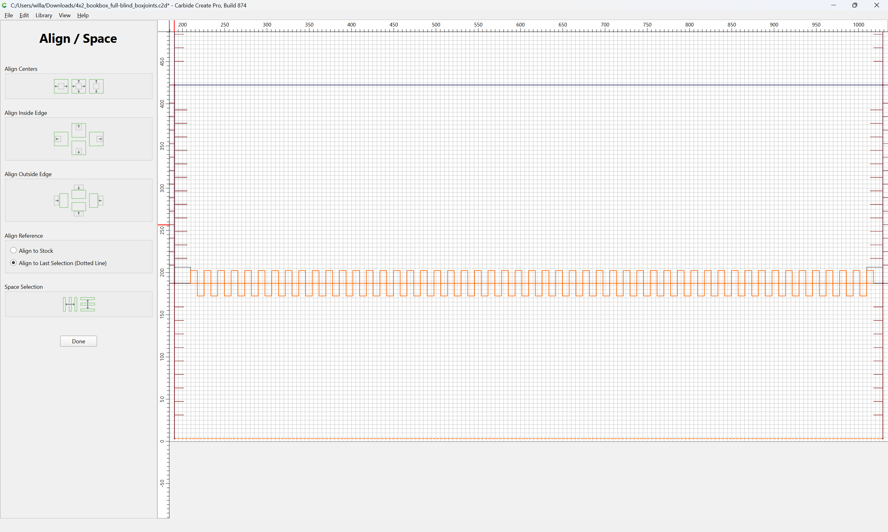
Center
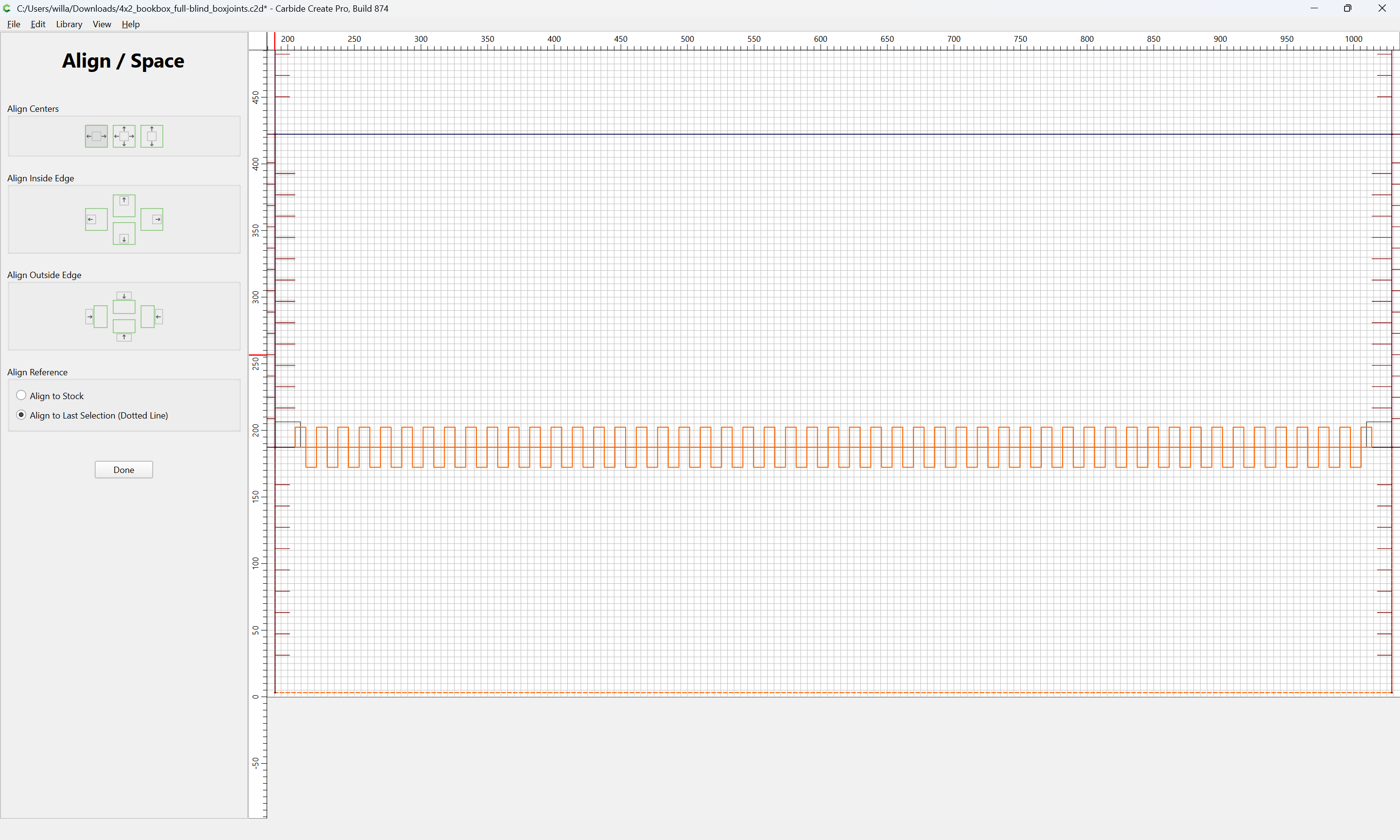
Done
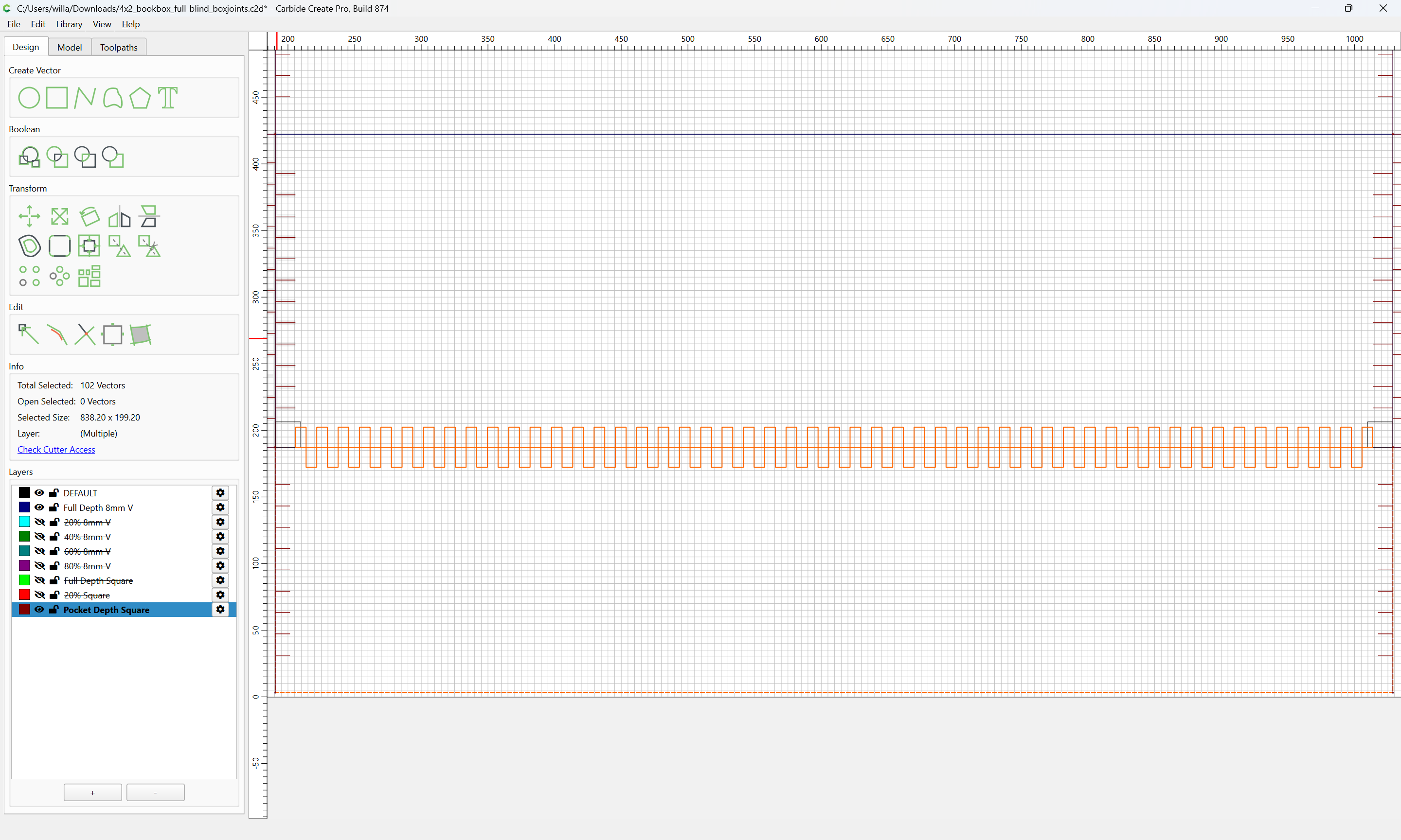
Zoom in on one edge:
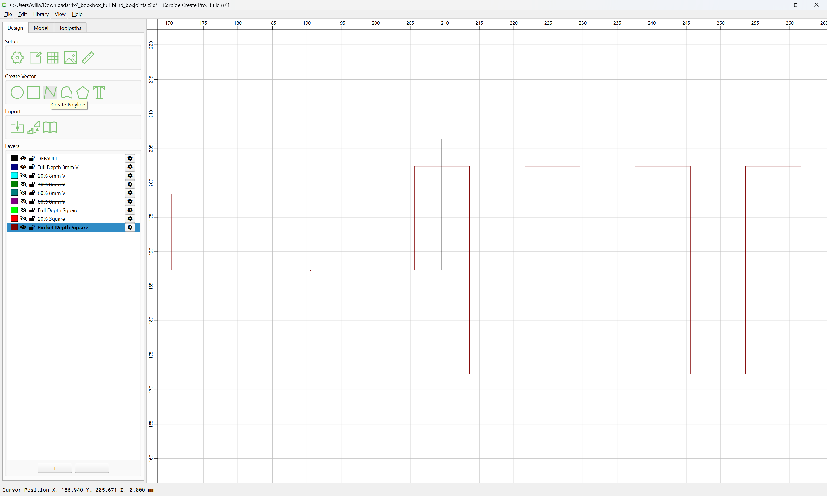
and draw one unit:
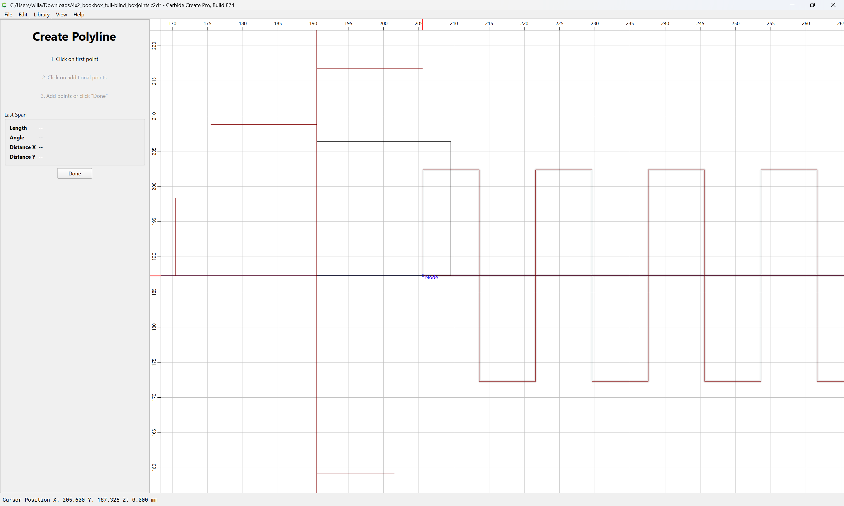
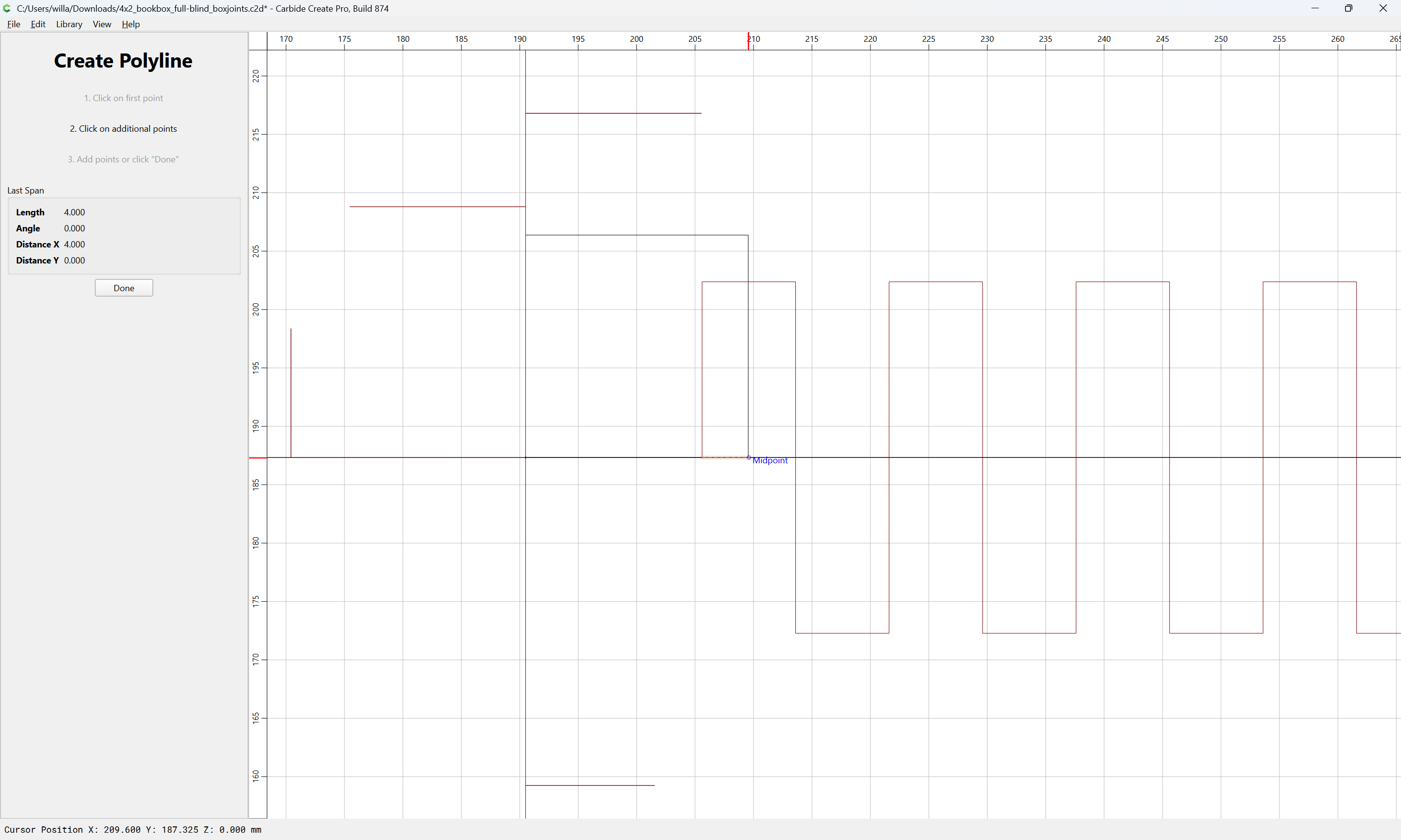
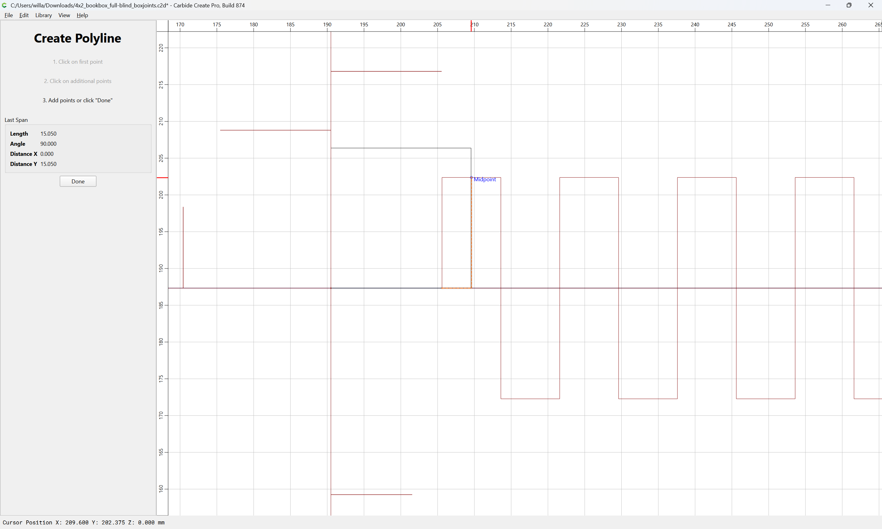
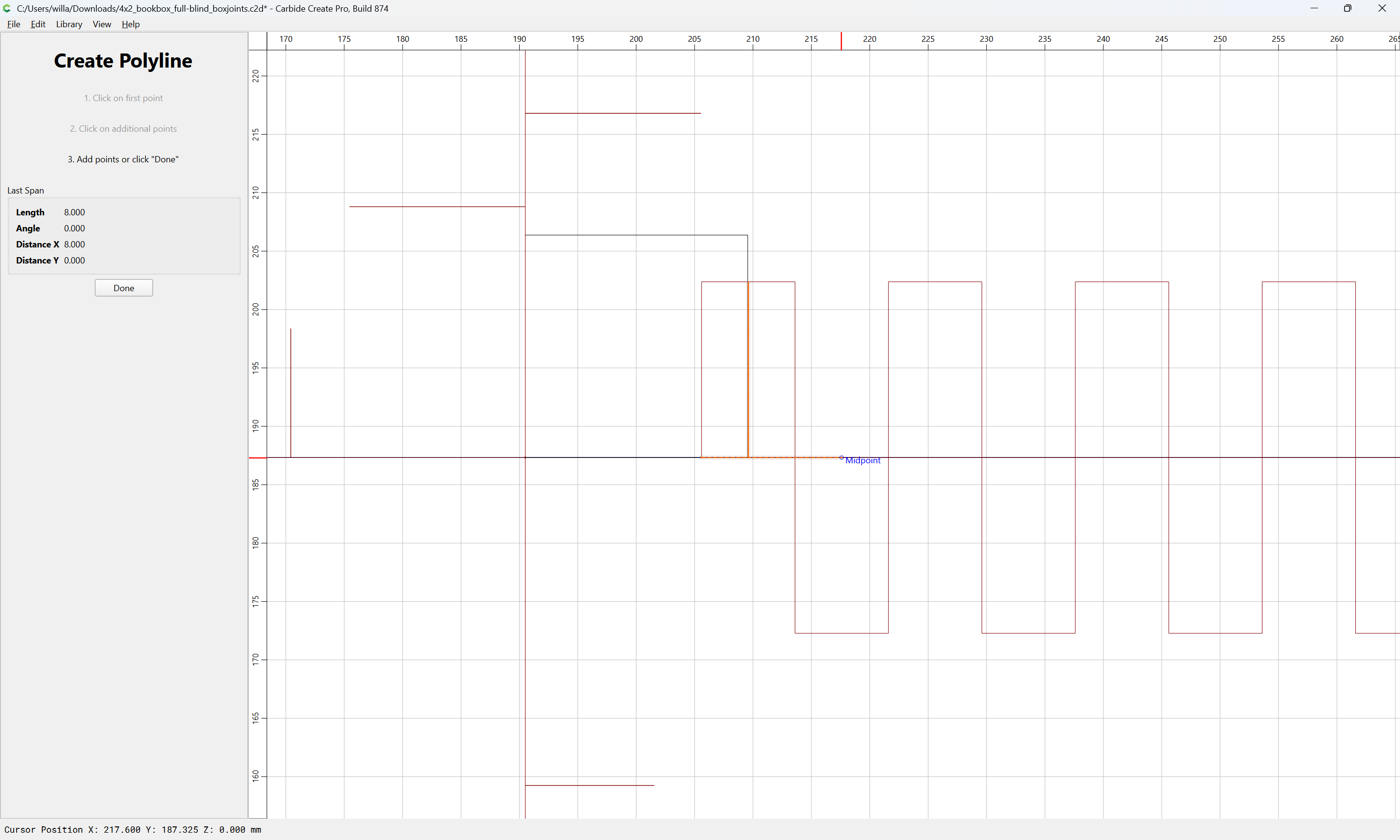
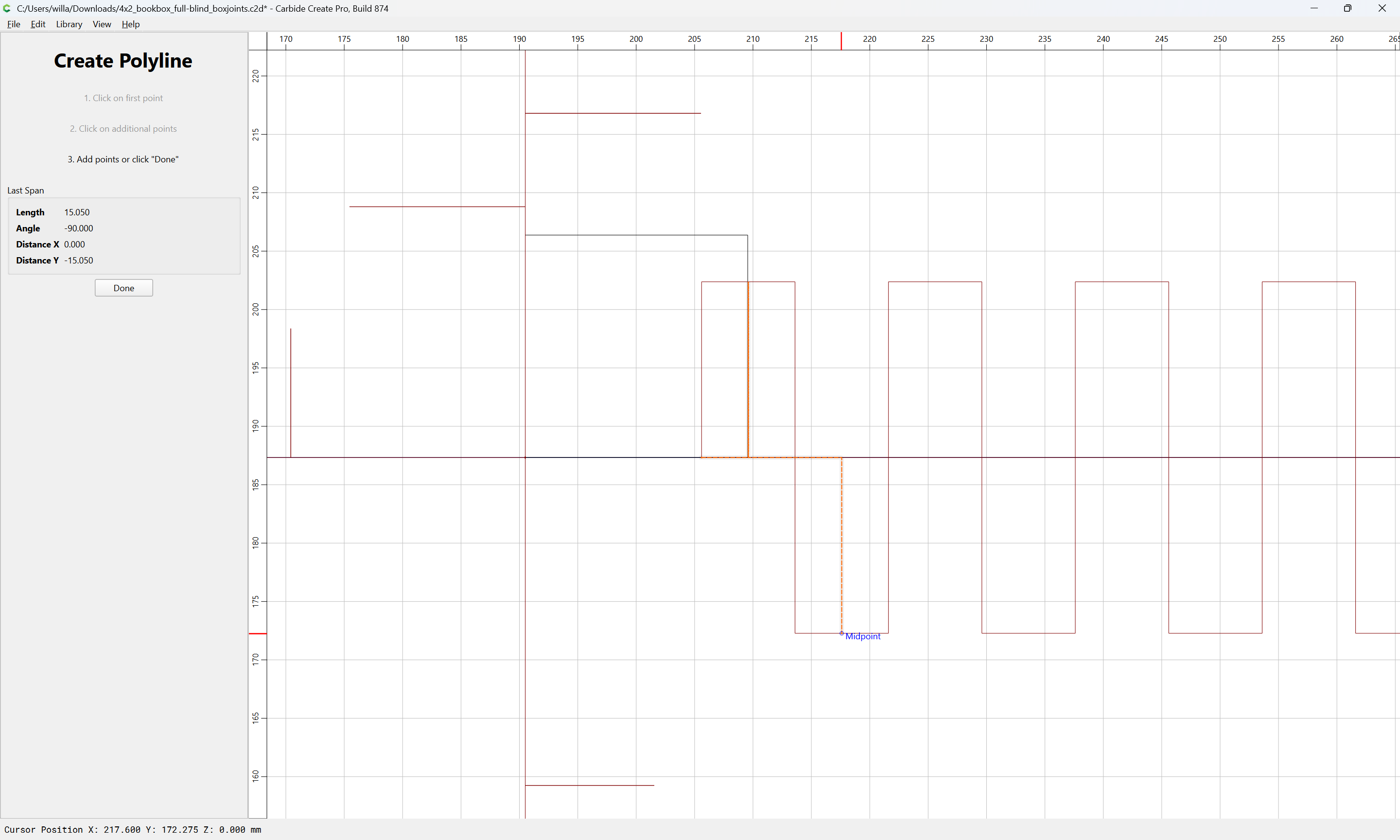
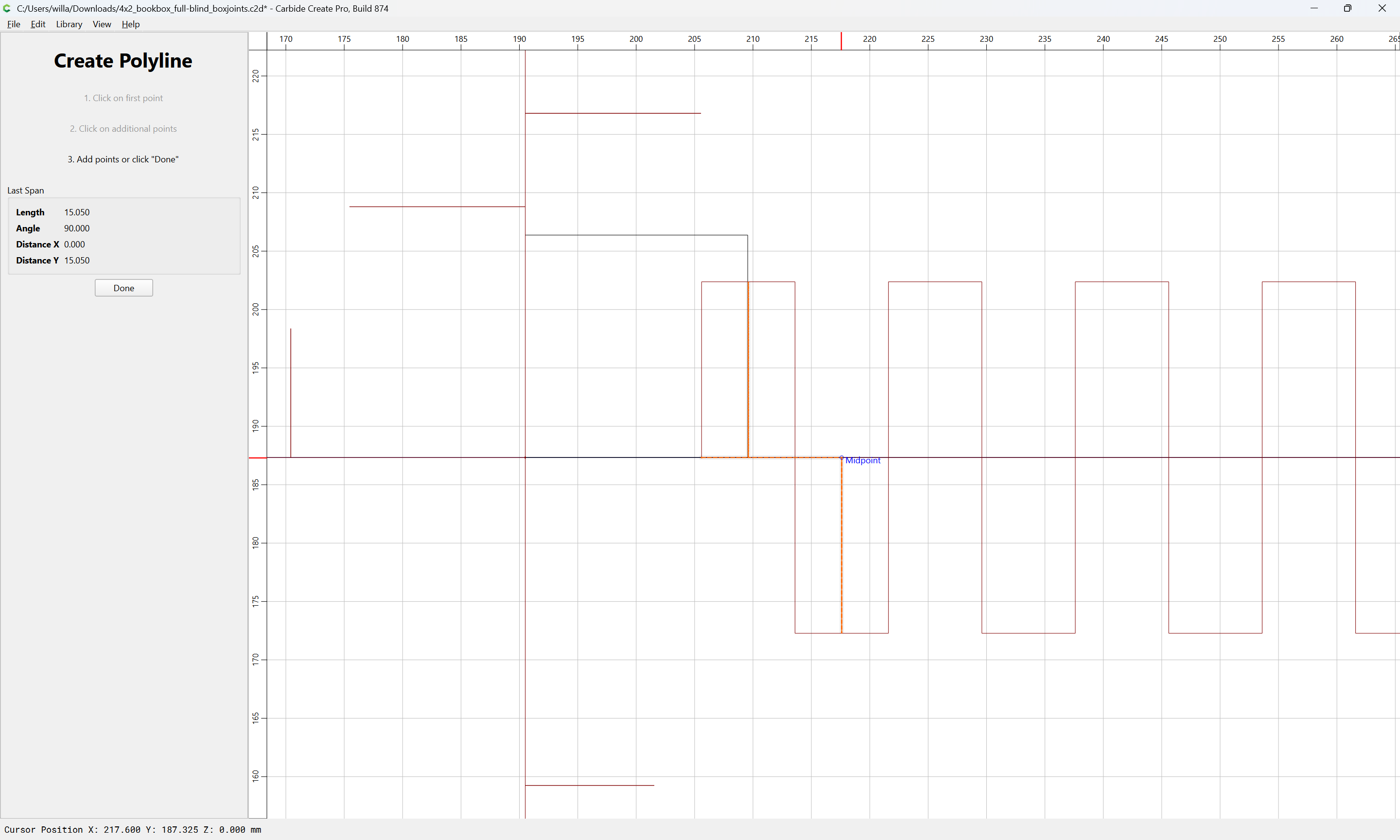
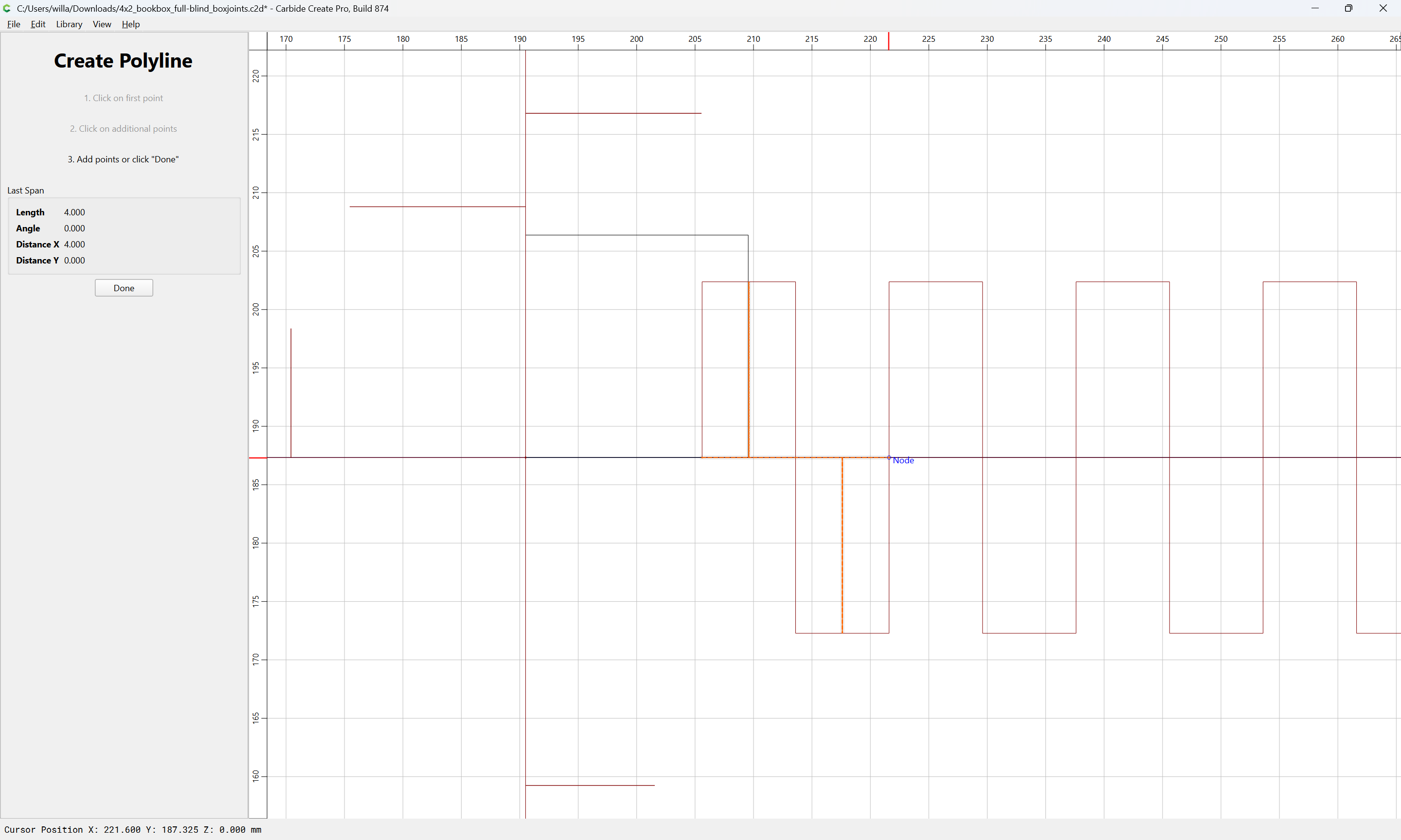
Done
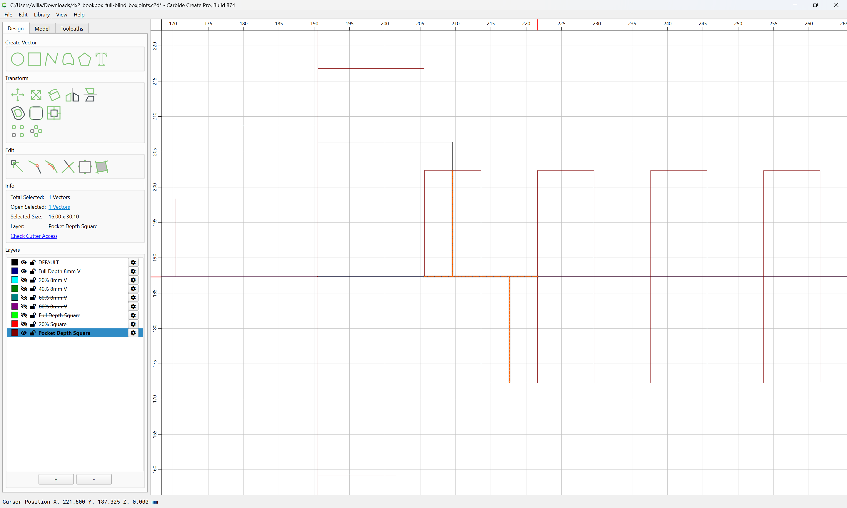
Use Linear Array to replicate as needed:
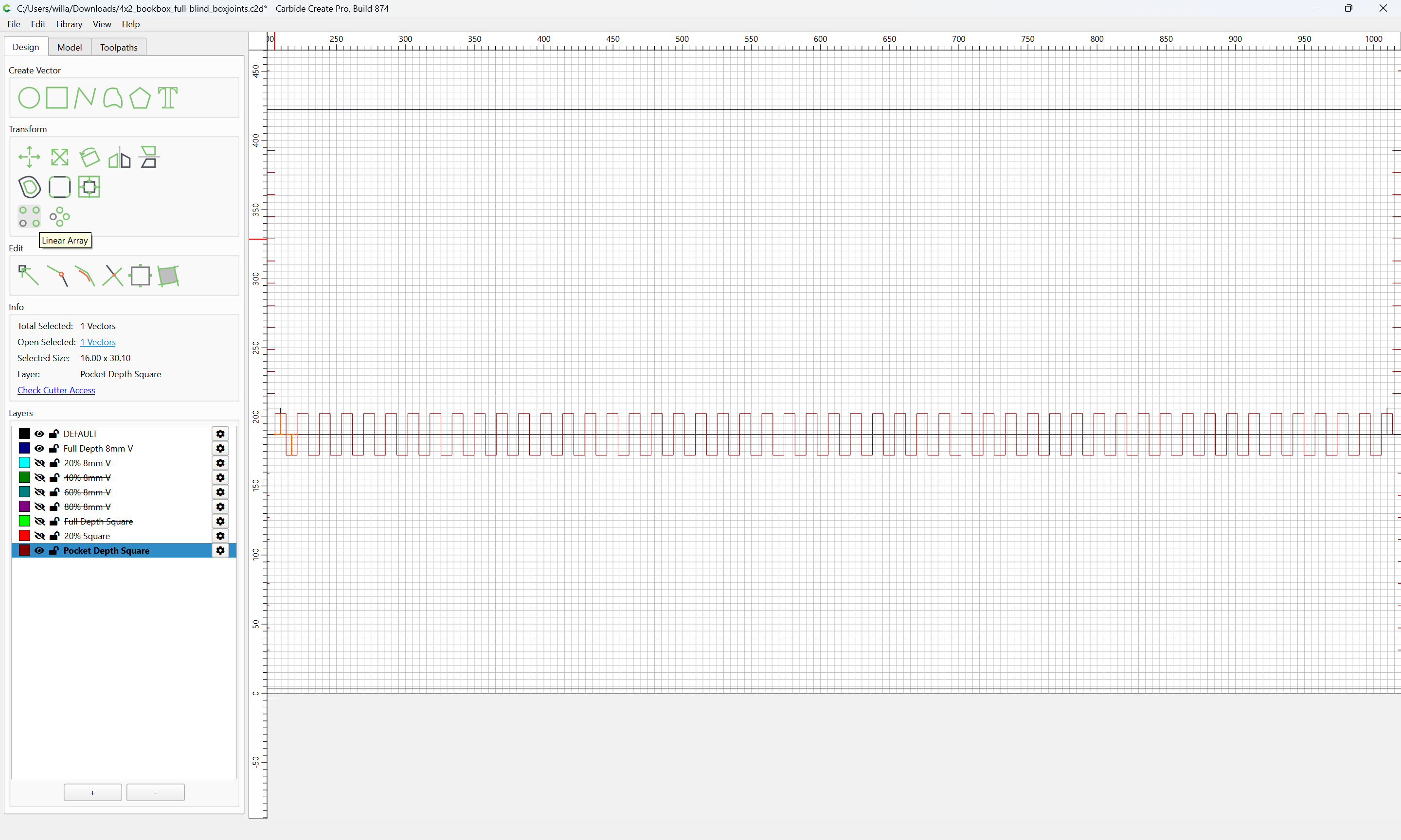
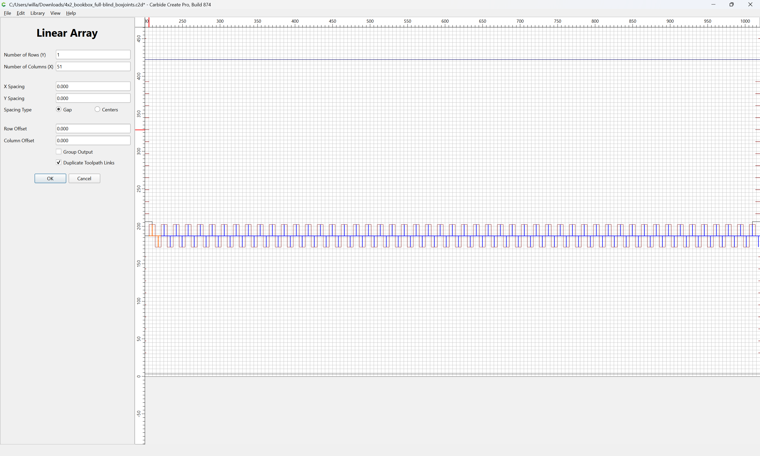
OK
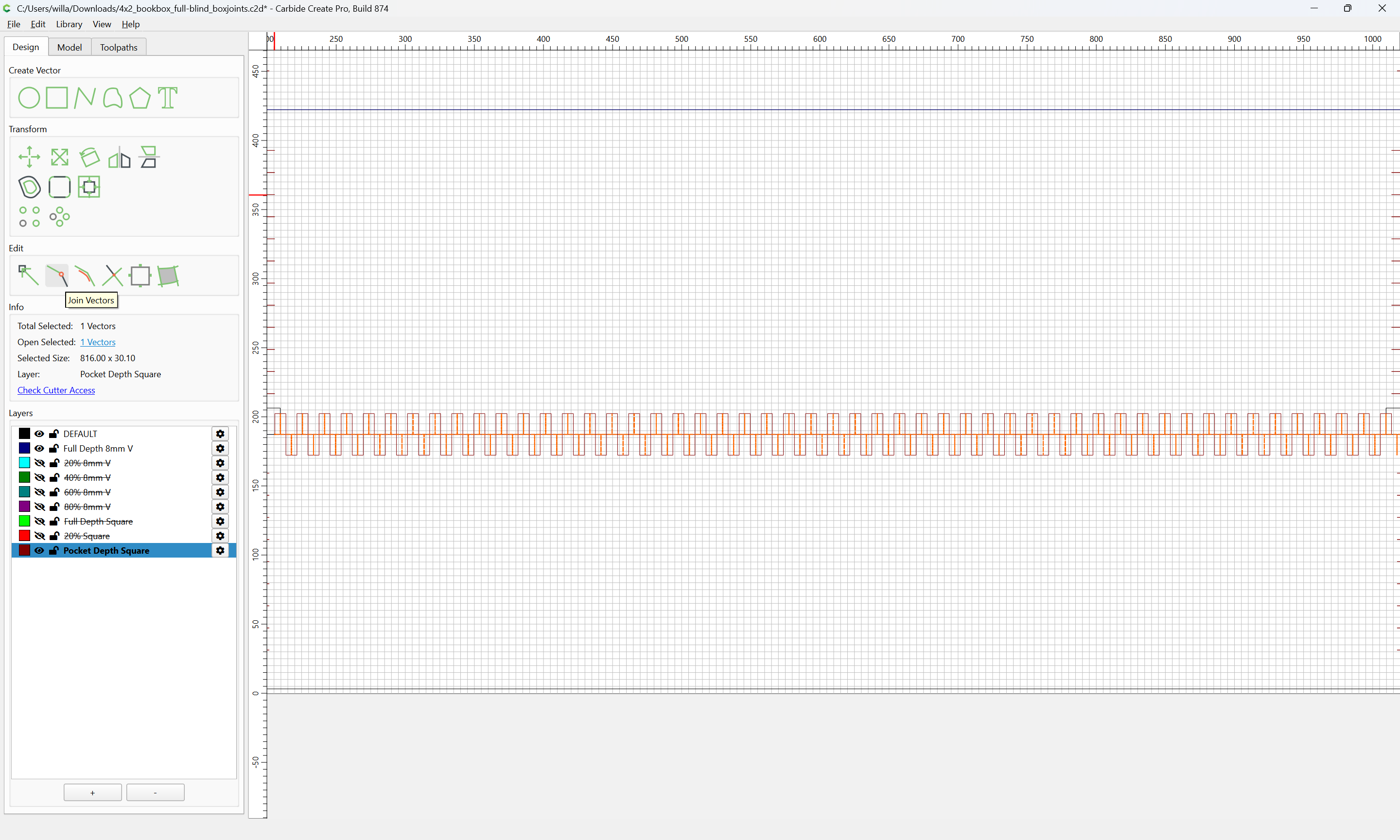
Join Vectors
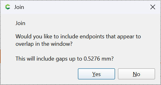
Yes
As before, delete the rectangular Linear Array:
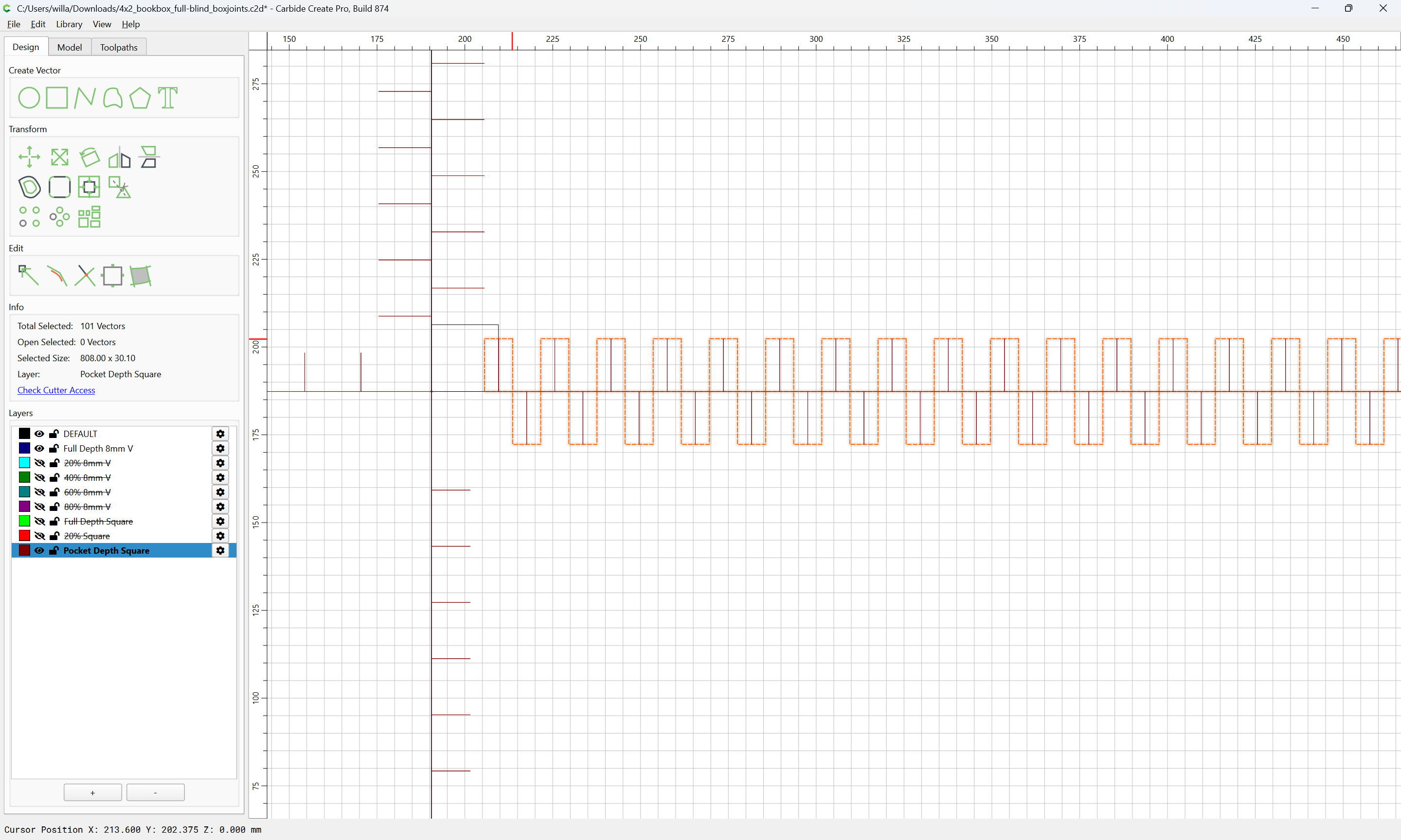
delete
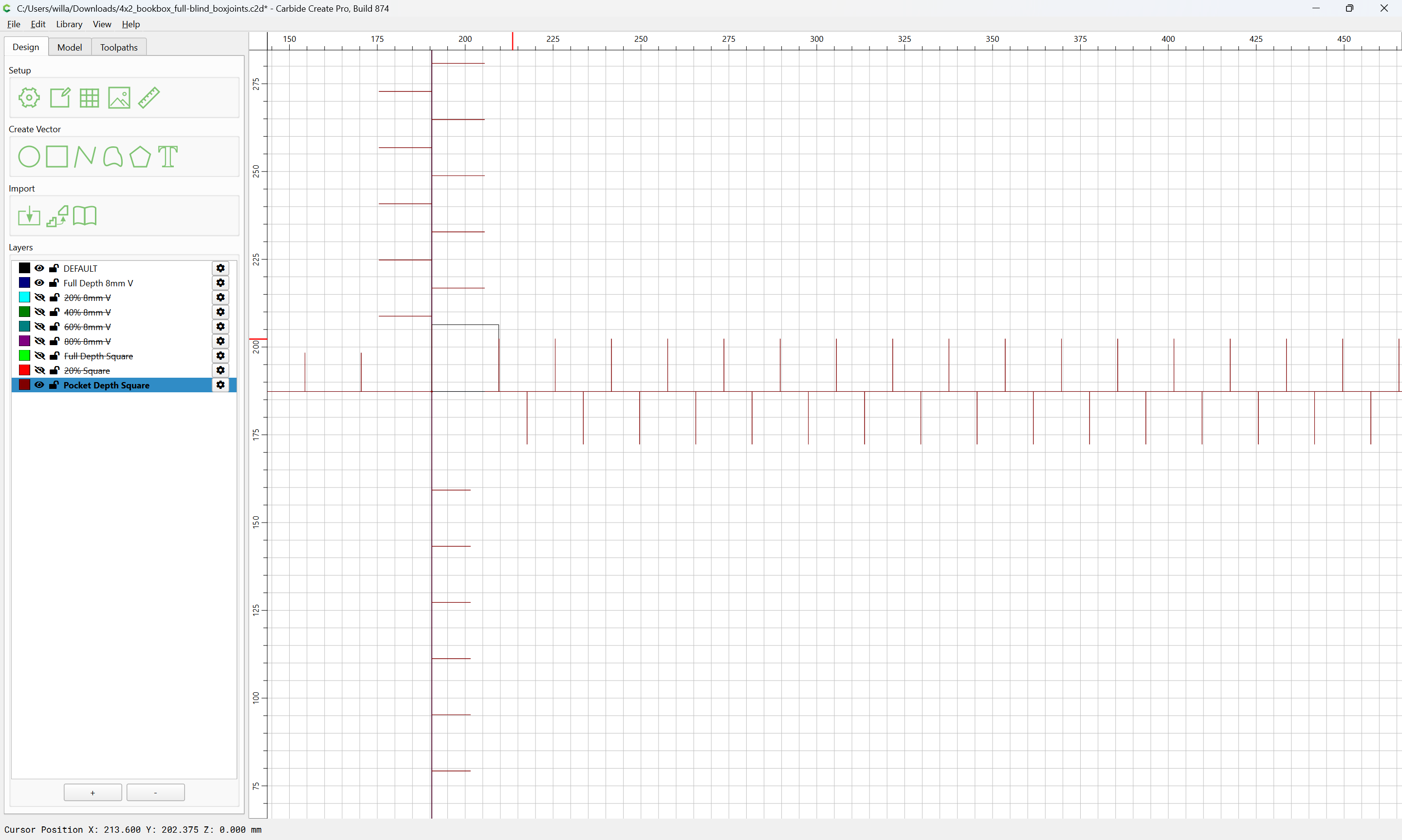
draw in the ends:
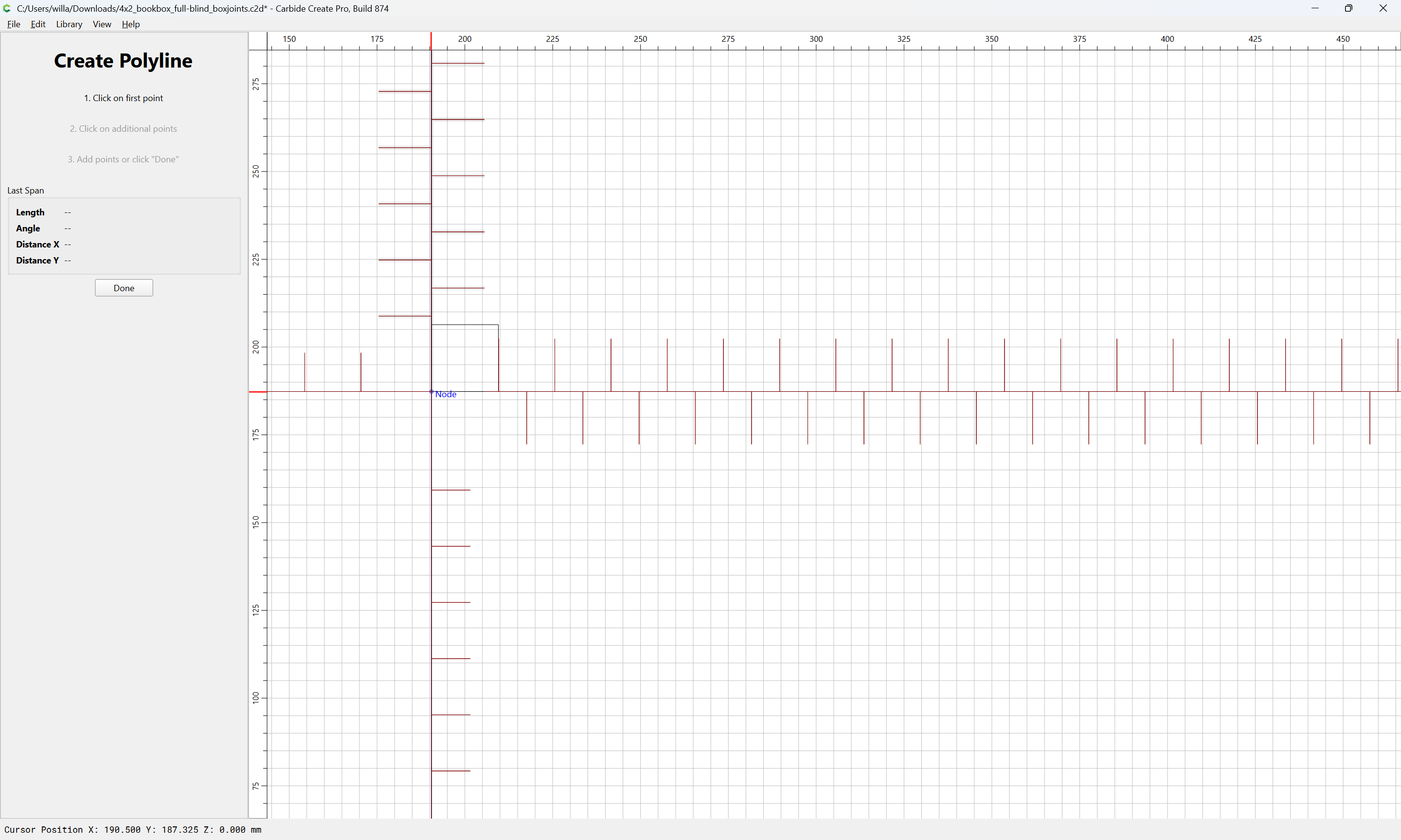
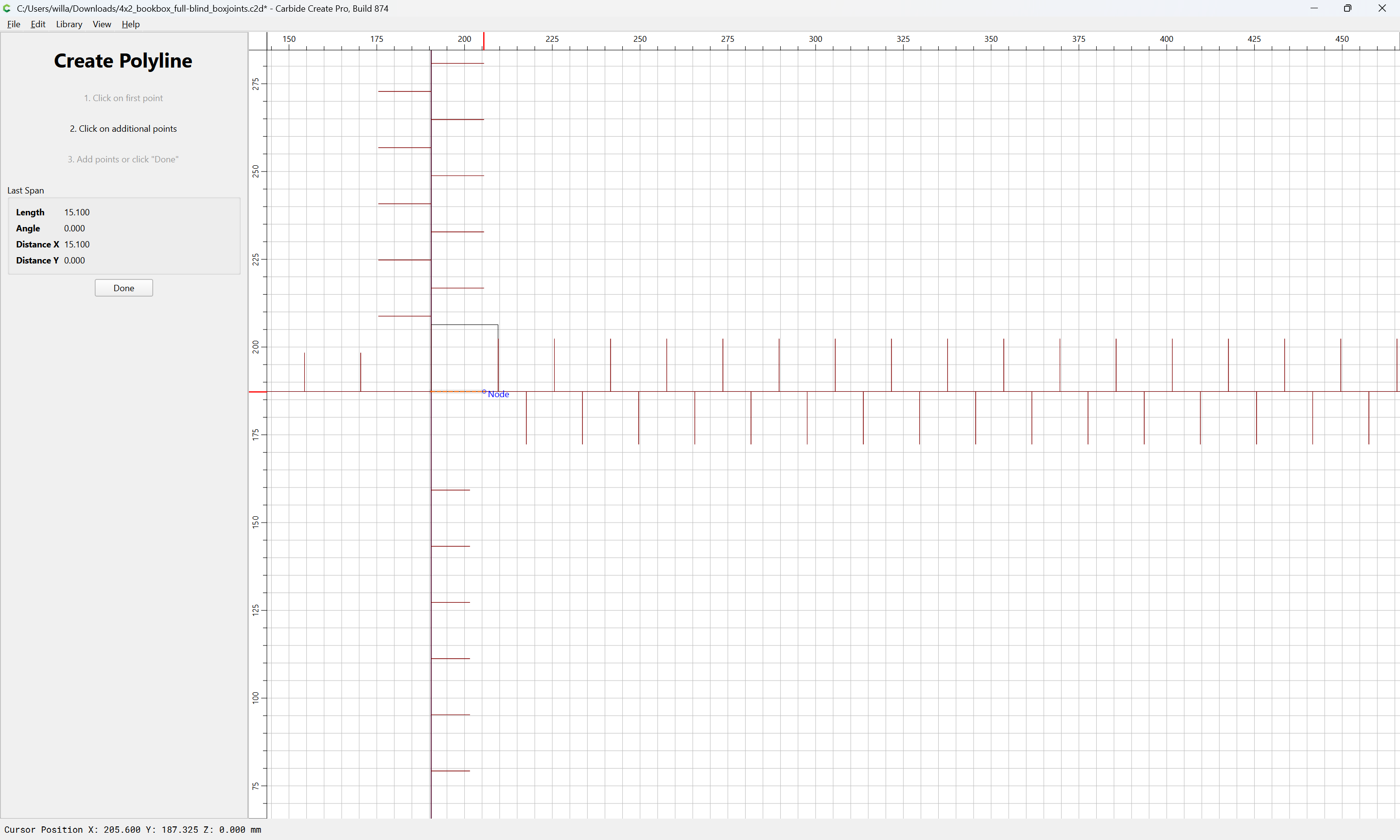
Done
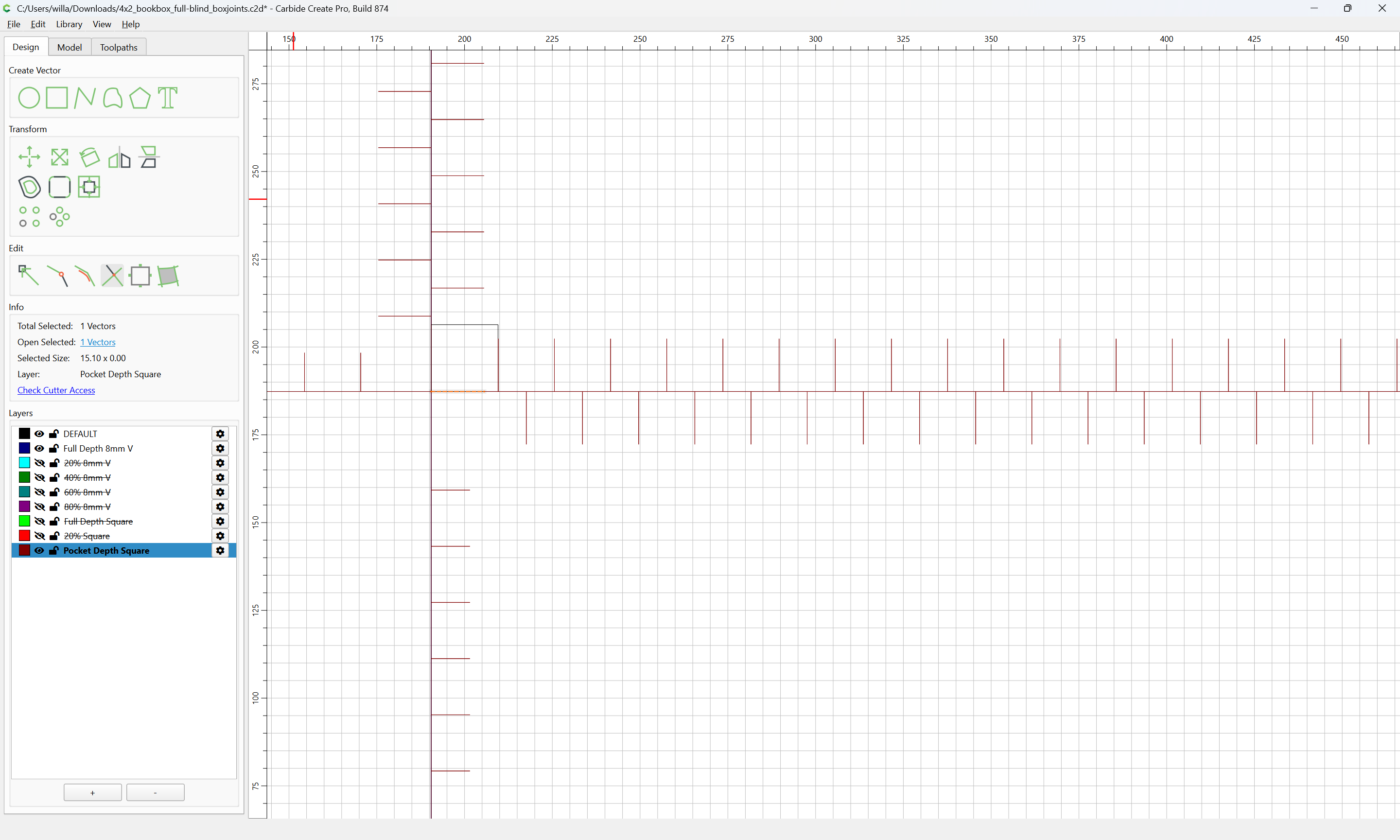
shift-click to add to the selection:
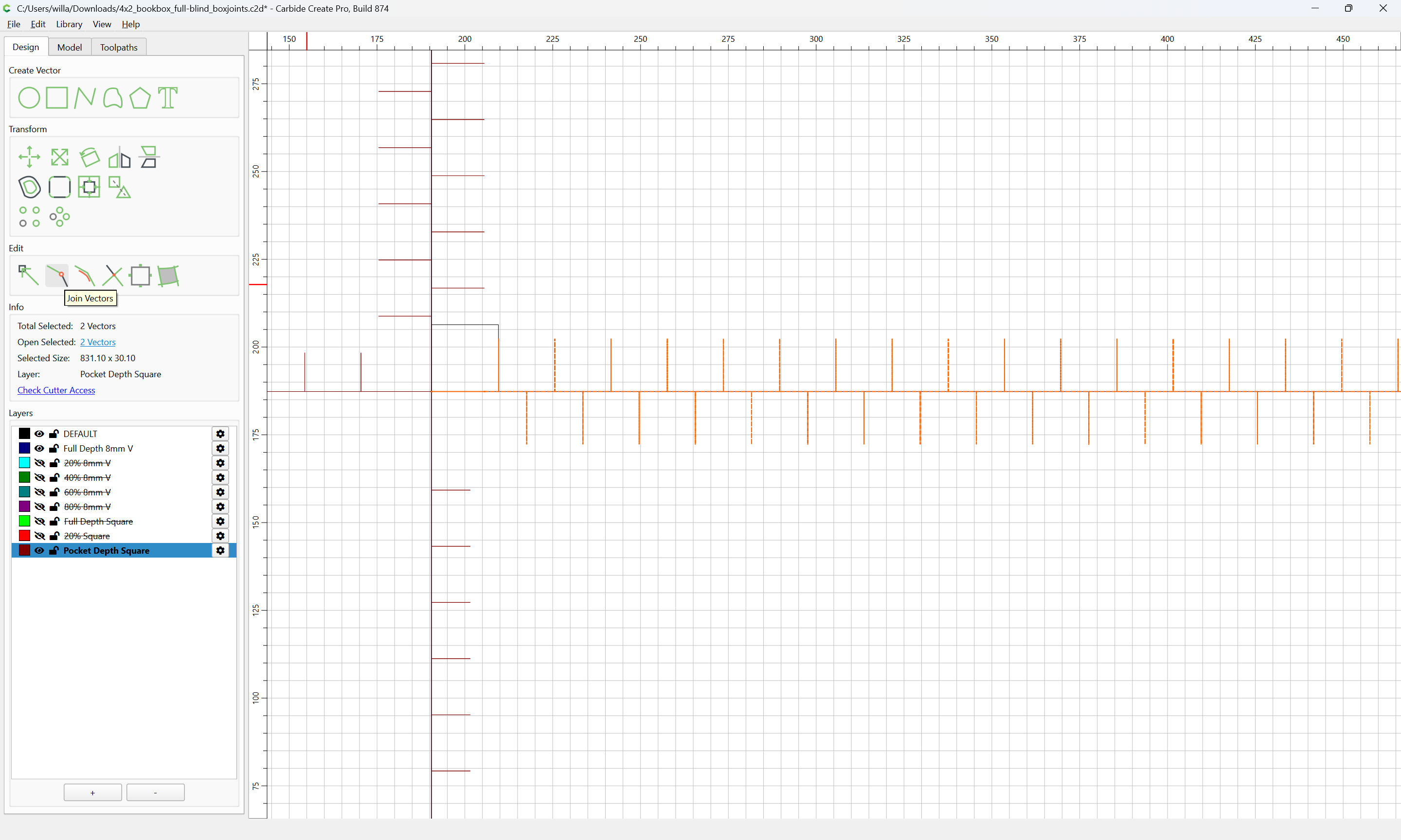
Join Vectors
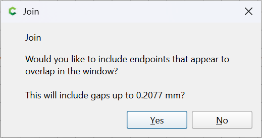
Yes
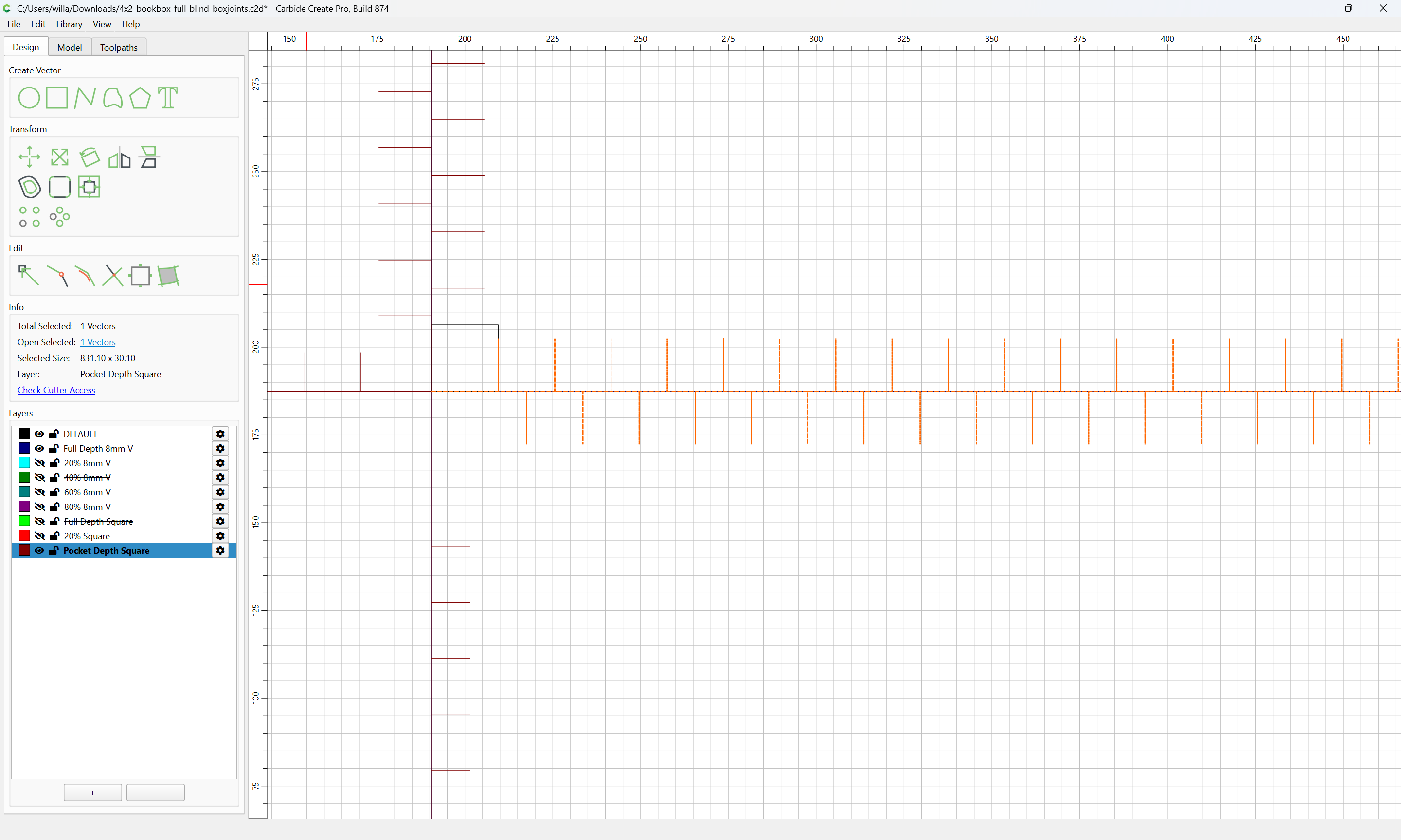
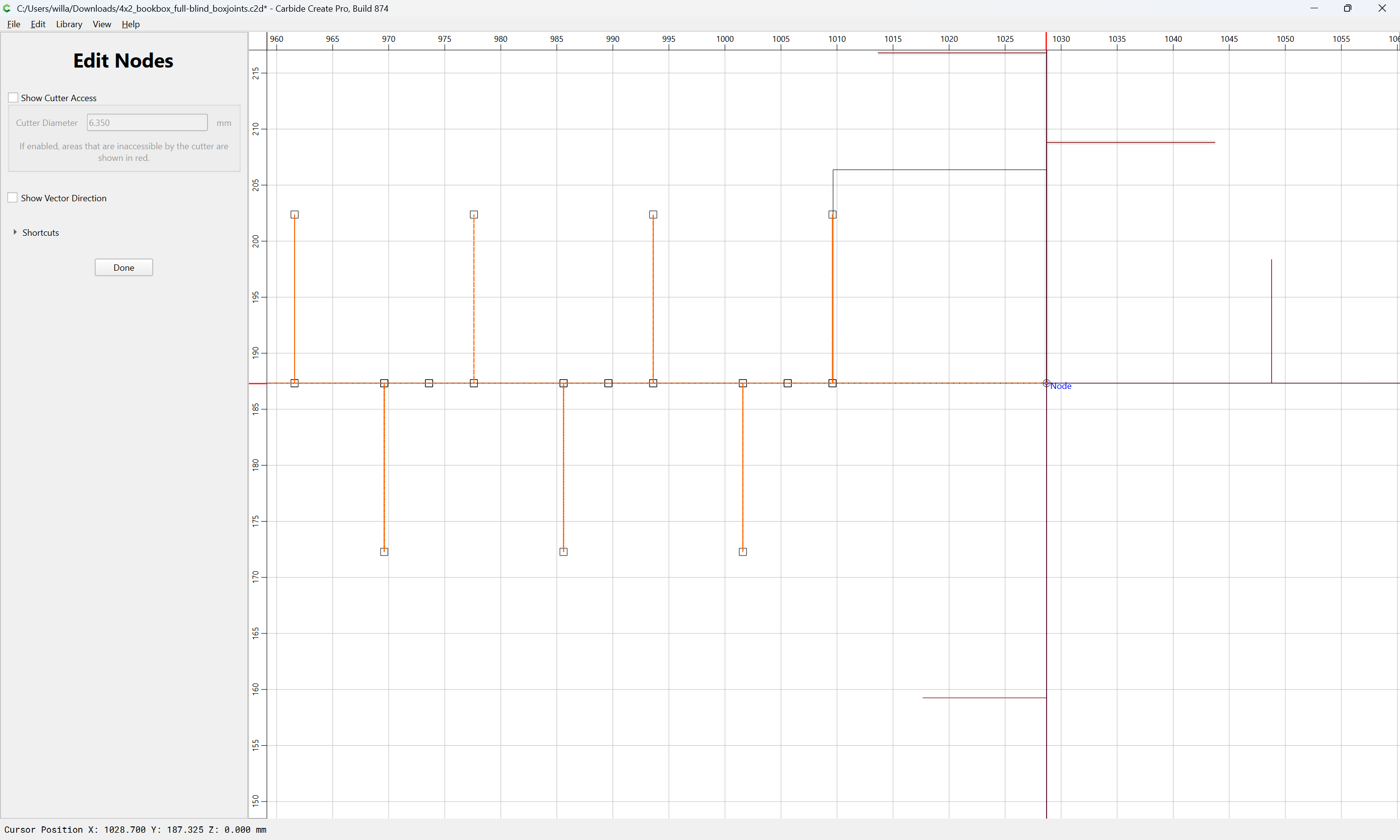
Duplicate
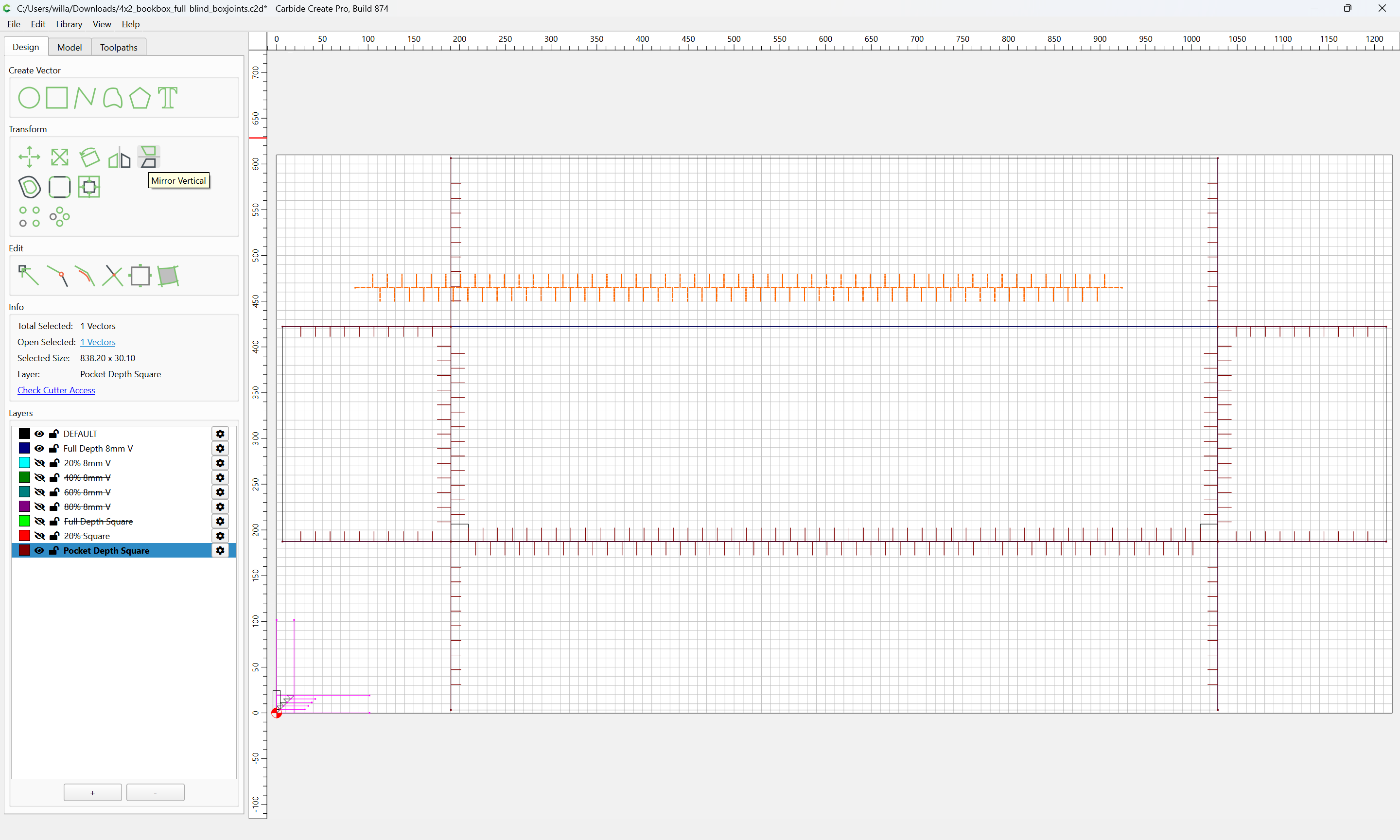
and Mirror Horizontal
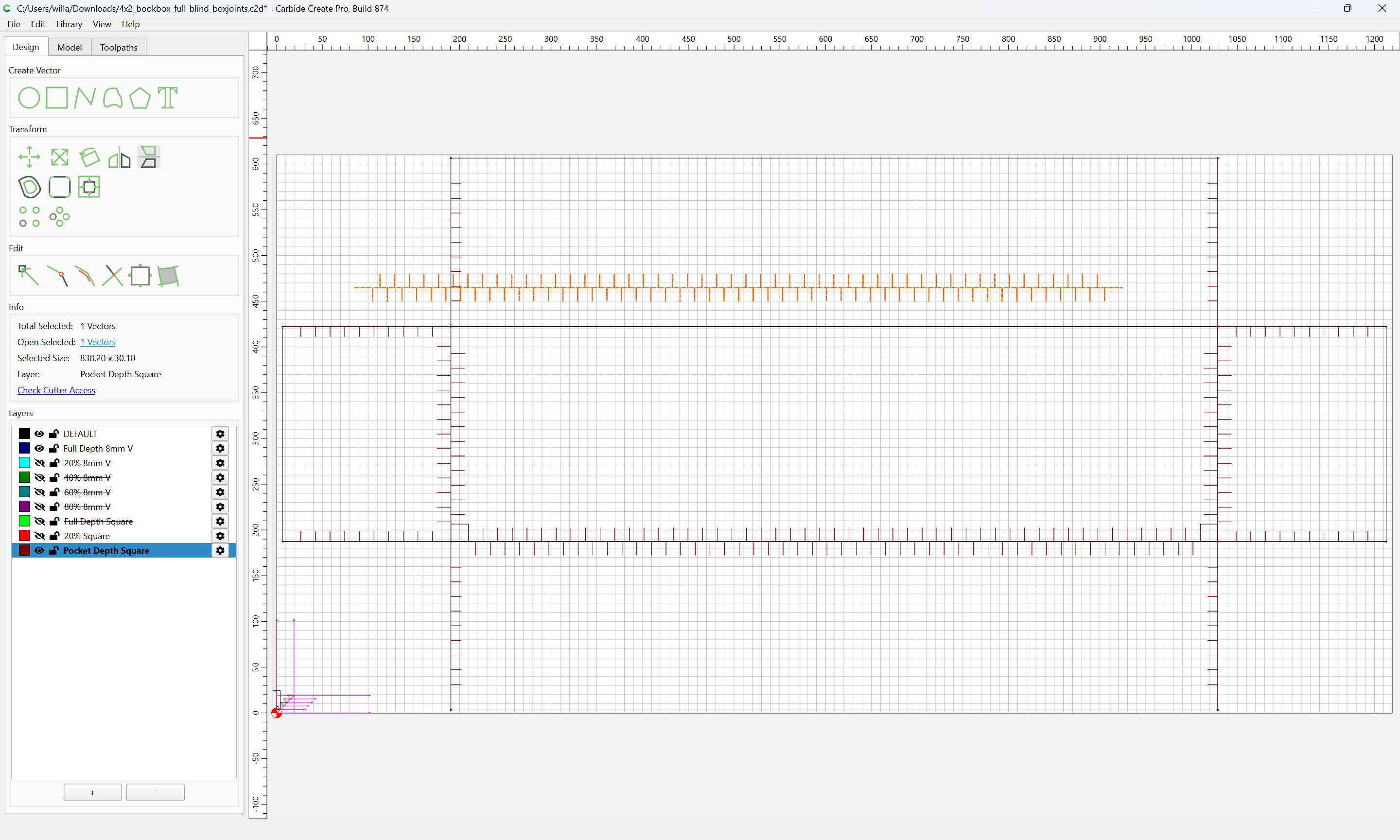
and drag into registration:
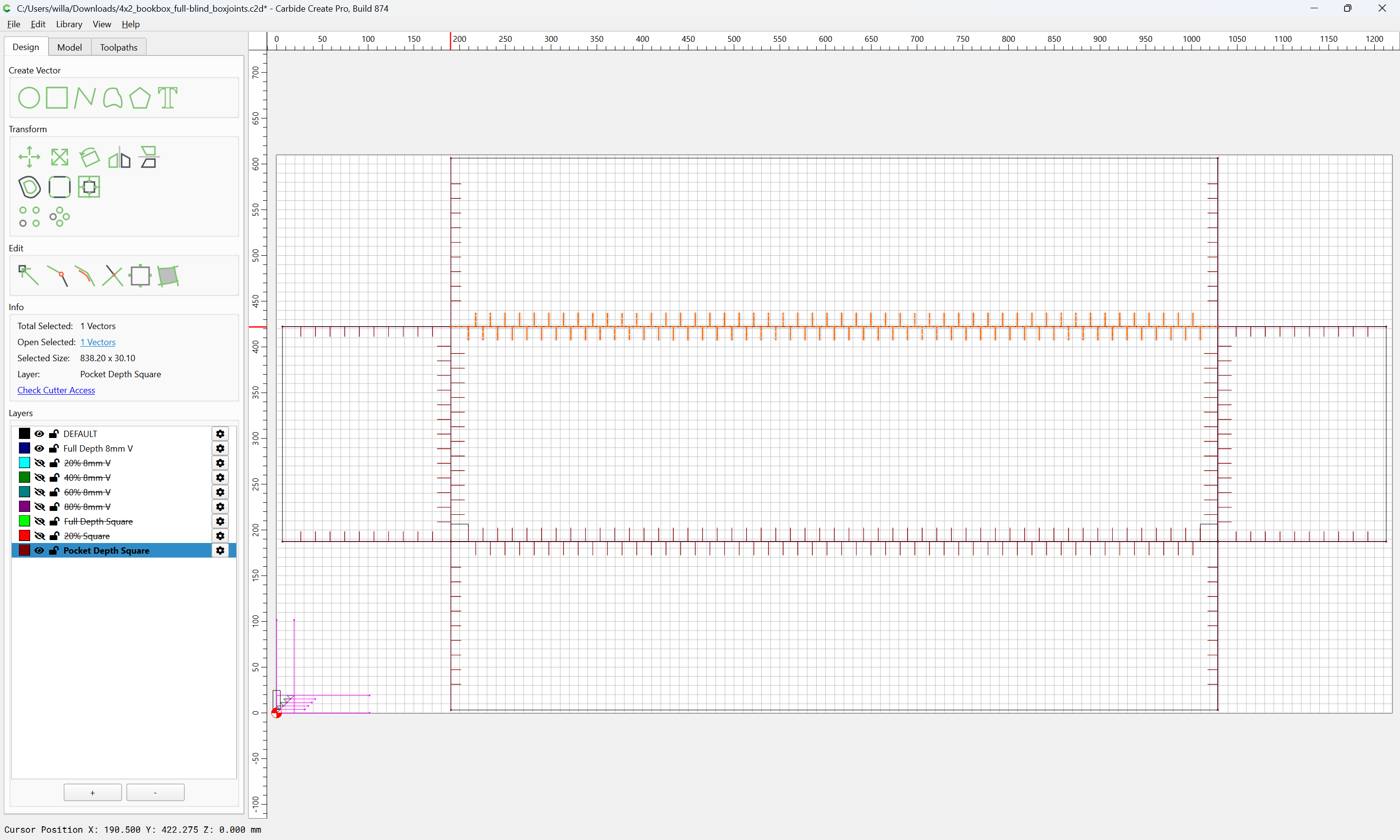
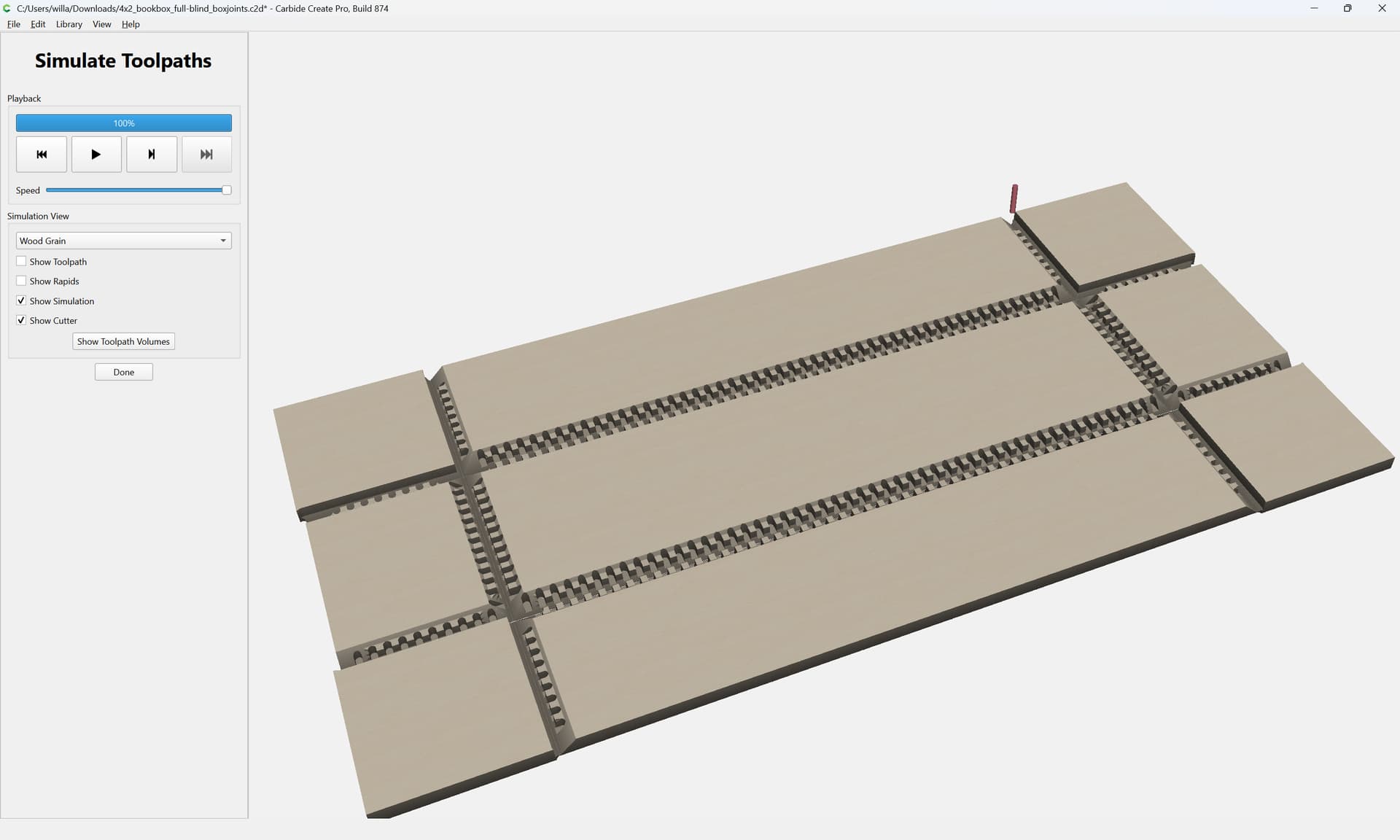
Lastly, review and optimize the toolpaths grouping them by tool used and ordering by necessary order of cutting…
Disable all the toolpaths:
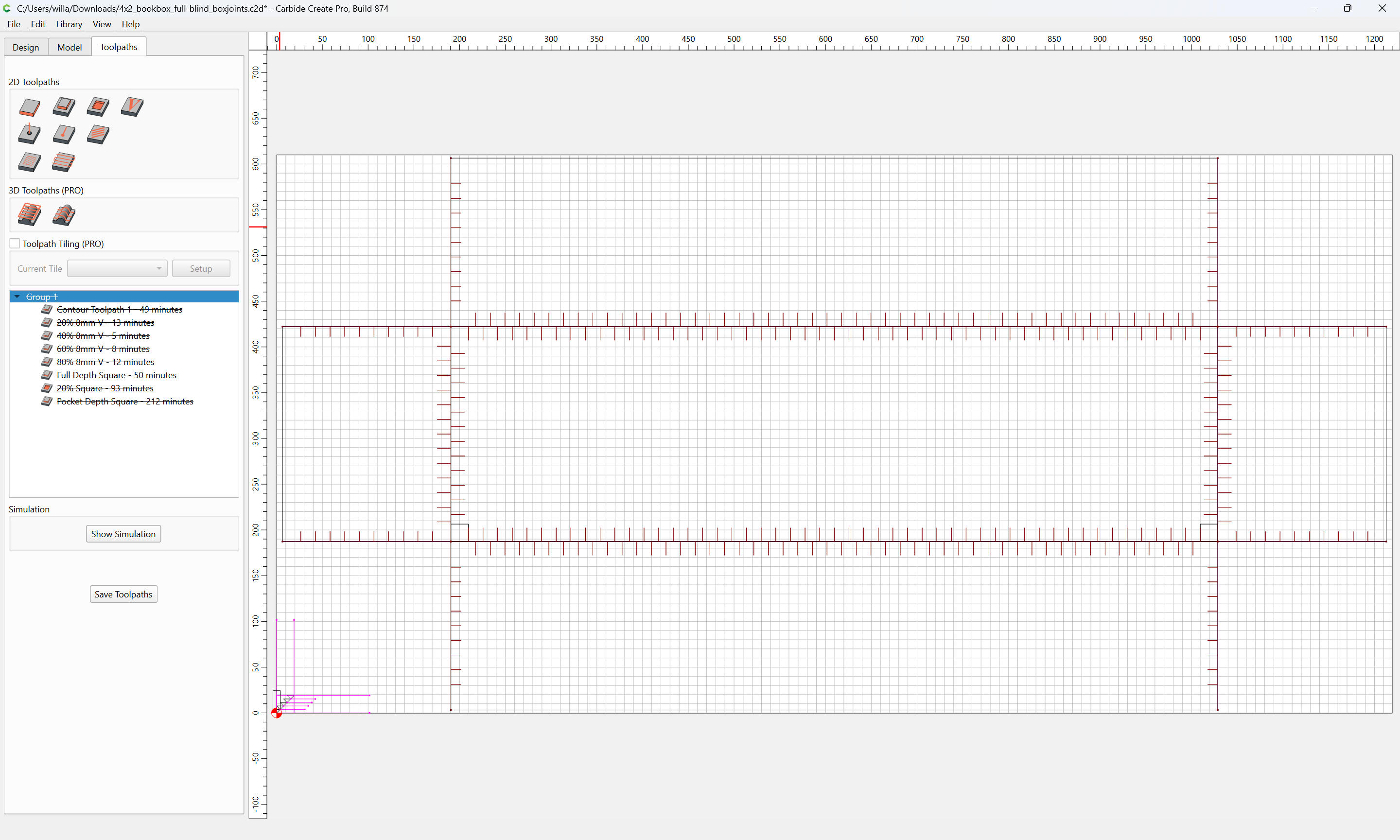
and make a new toolpath group for the first tool to be used and drag in and enable the first toolpath:

Verify the simulation:
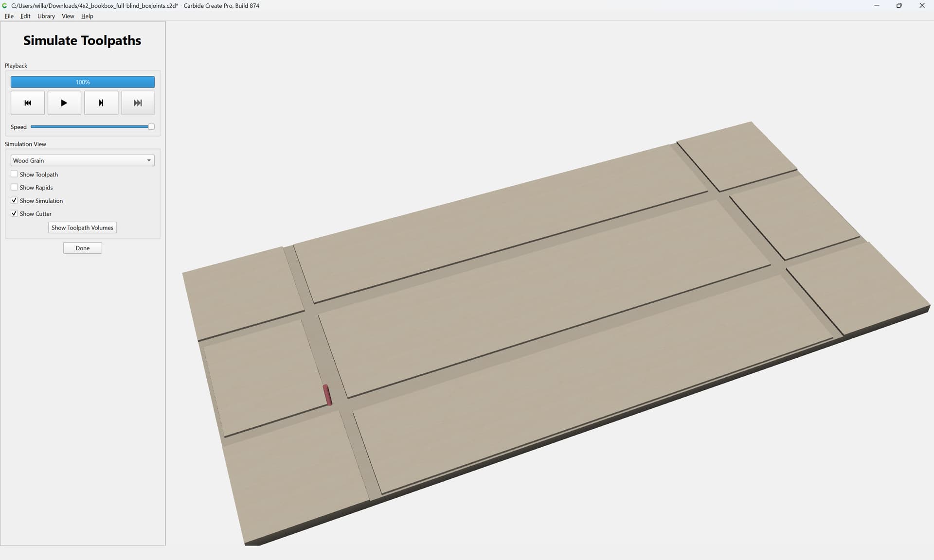
then drag in the second toolpath and edit it to take into account what was cut previously:
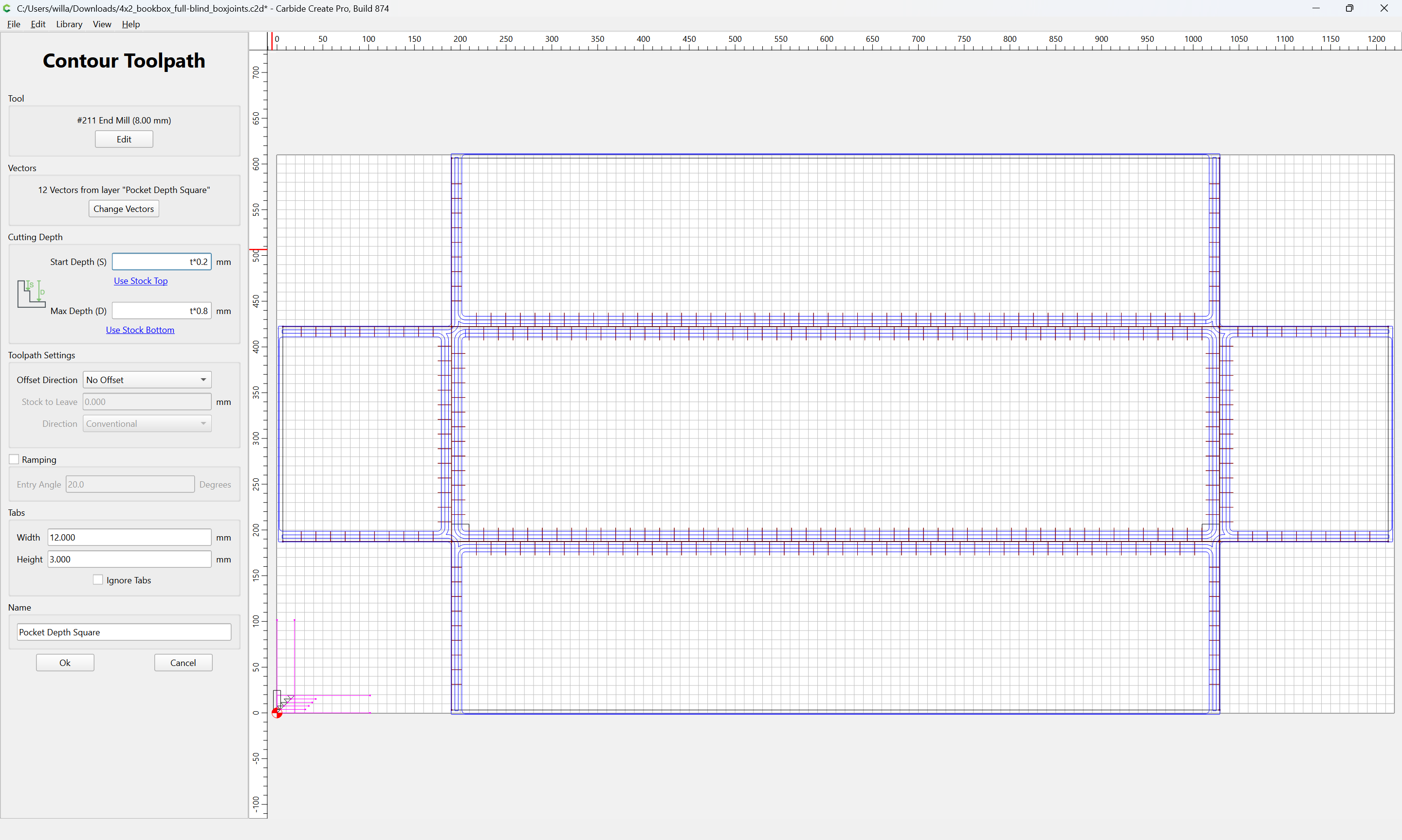
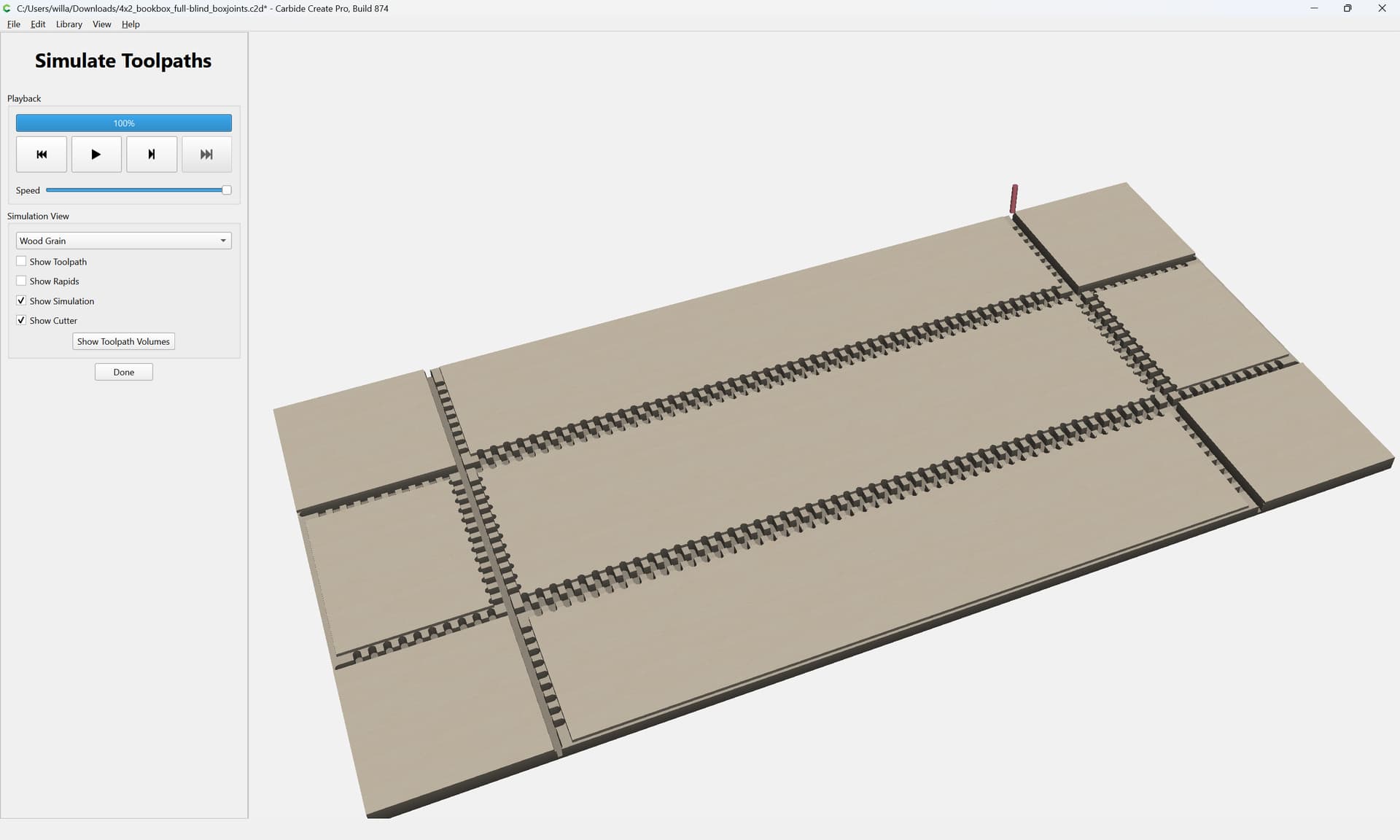
For the V-tooling while half the stock will have been removed for the first pass, it will be best practice to start it at the top:
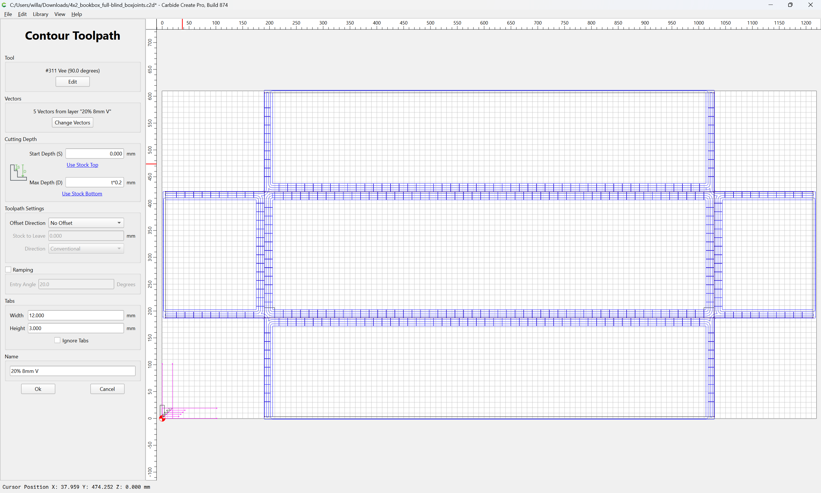
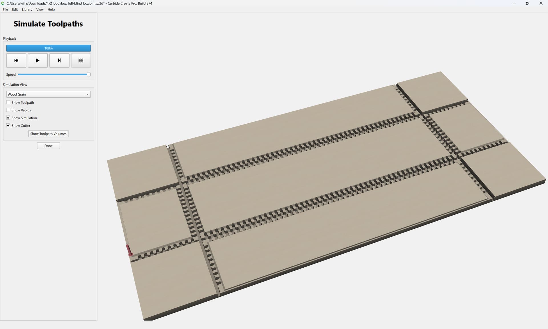
but for the balance, they may start at the bottom of the shallow square pocket:

The final V toolpath may start at the bottom of the Square cut to Pocket Depth:
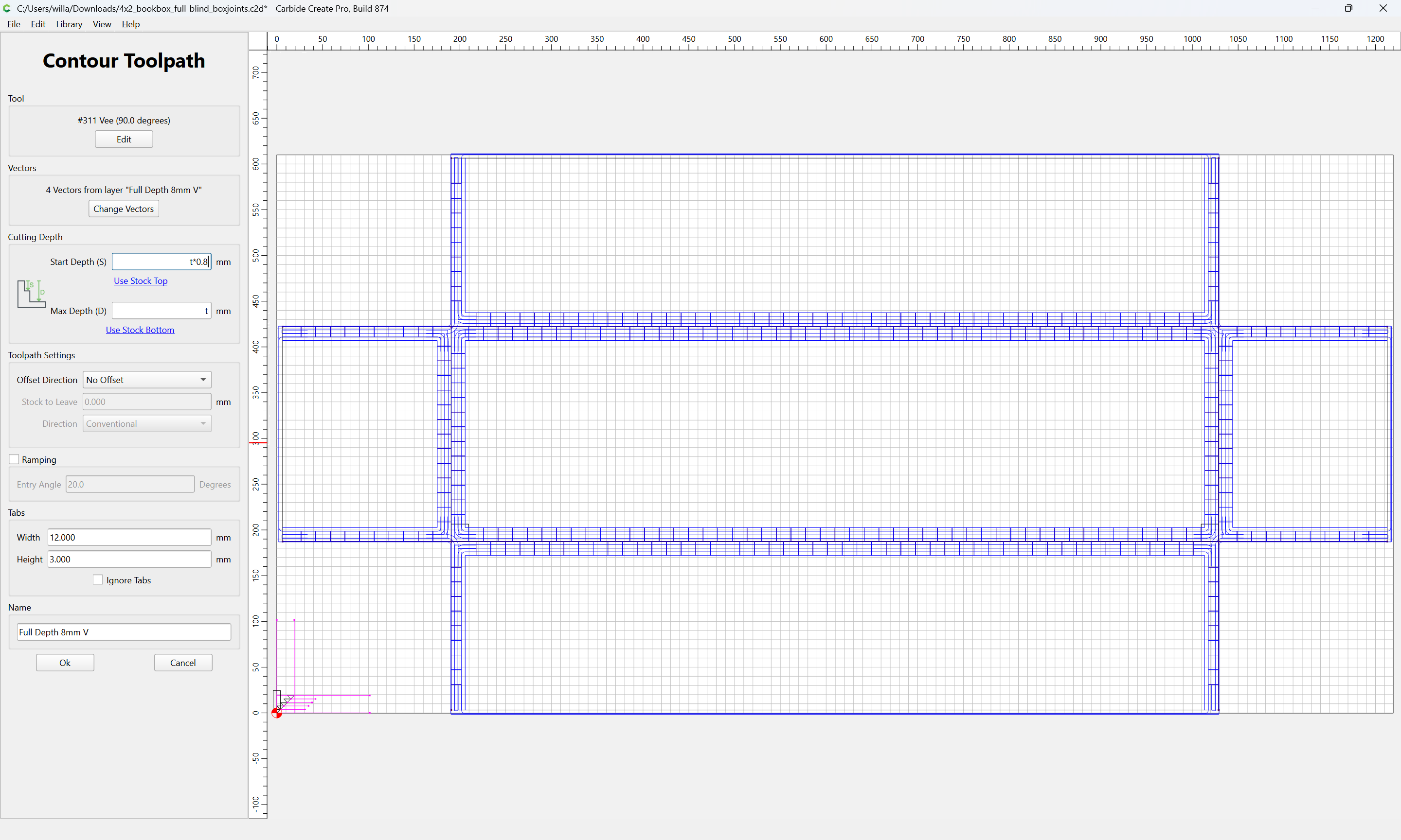
netting some real time savings:
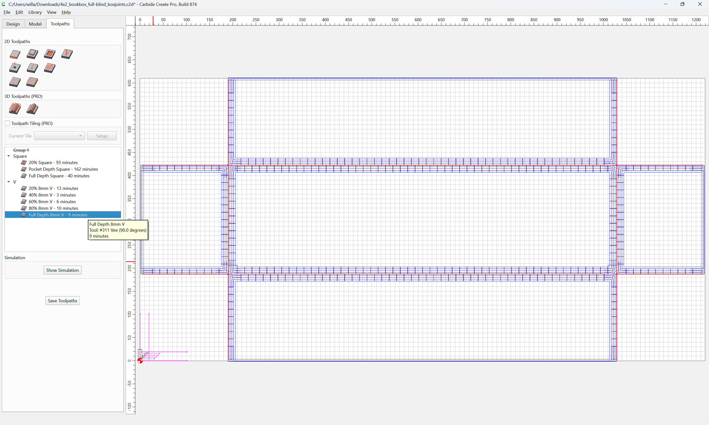
However, in retrospect, the Square Pocket toolpaths should not have been shortened…
Each set may be selected:
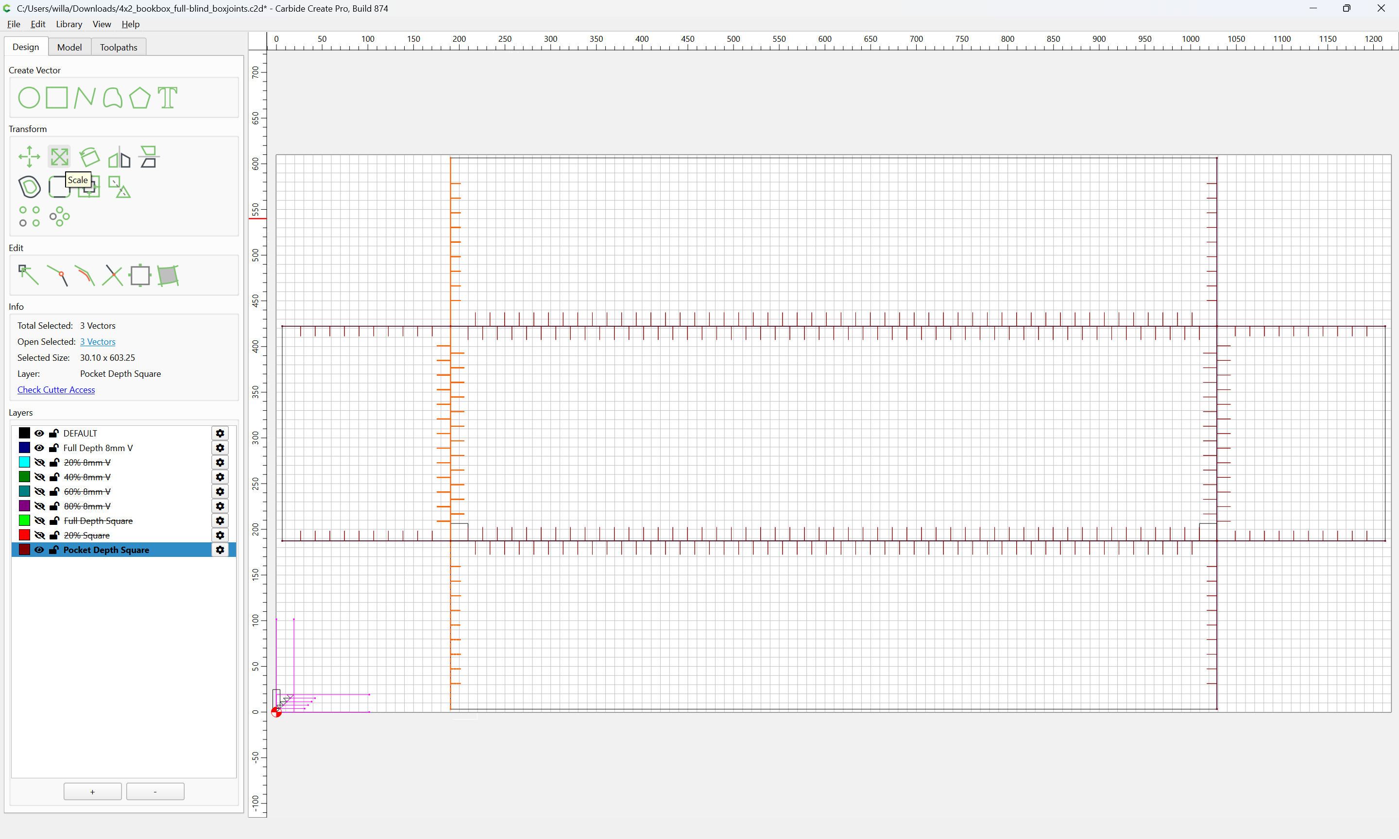
Scaled:
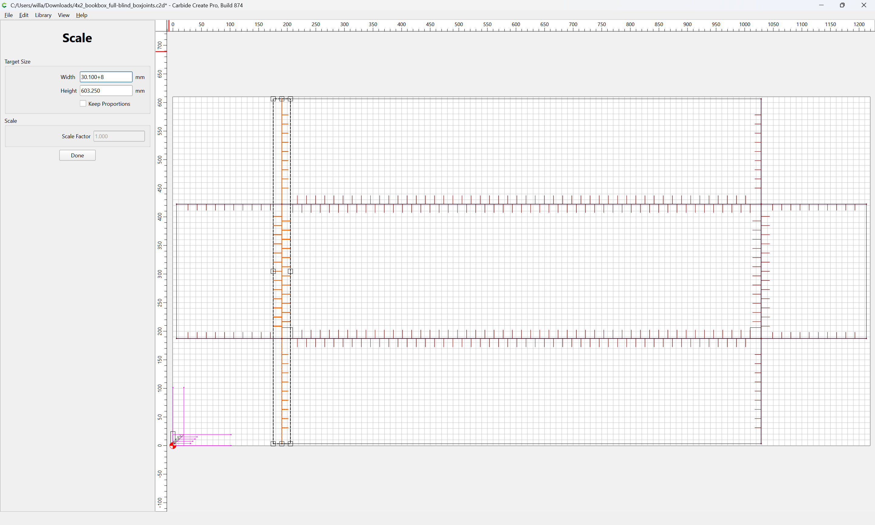
Done
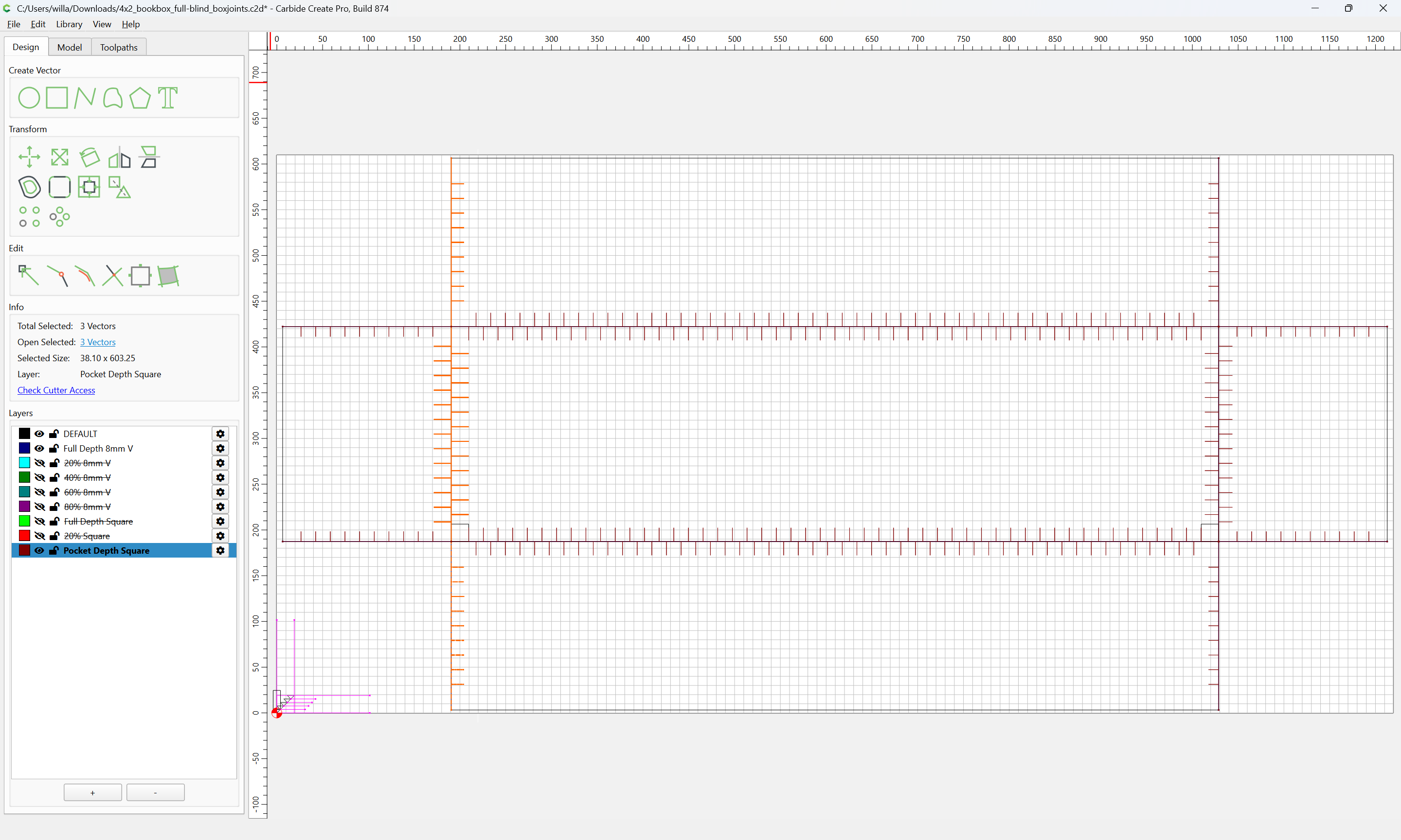
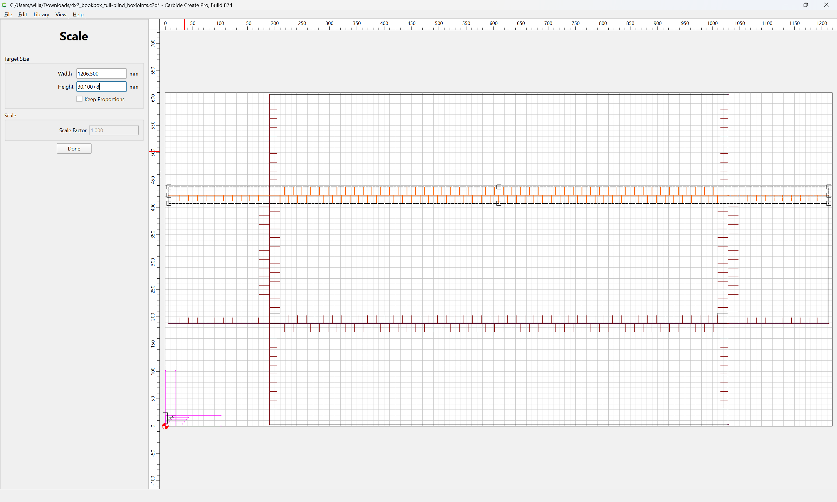
Adjust as desired until one arrives at a preview which seems promising:
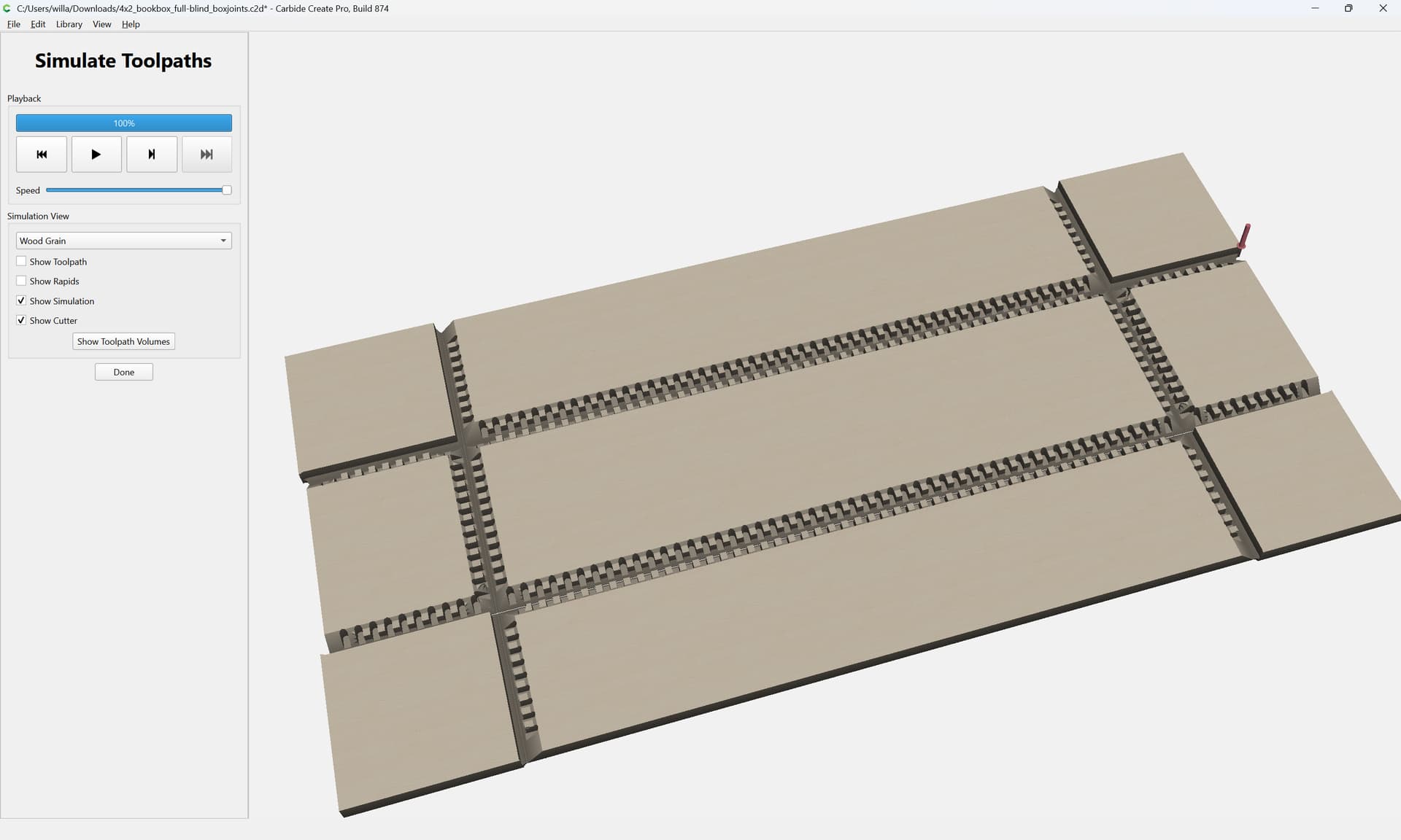
Then I would suggest duplicating this file and editing it down so as to test on a small-scale and verifying the fit of the joinery and adjusting as need be.
Note in particular that if using a belt-drive machine, one will want to calibrate for belt-stretch:
Attached as a v874 file:
4x2_bookbox_full-blind_boxjoints.c2d (156 KB)
2 Likes