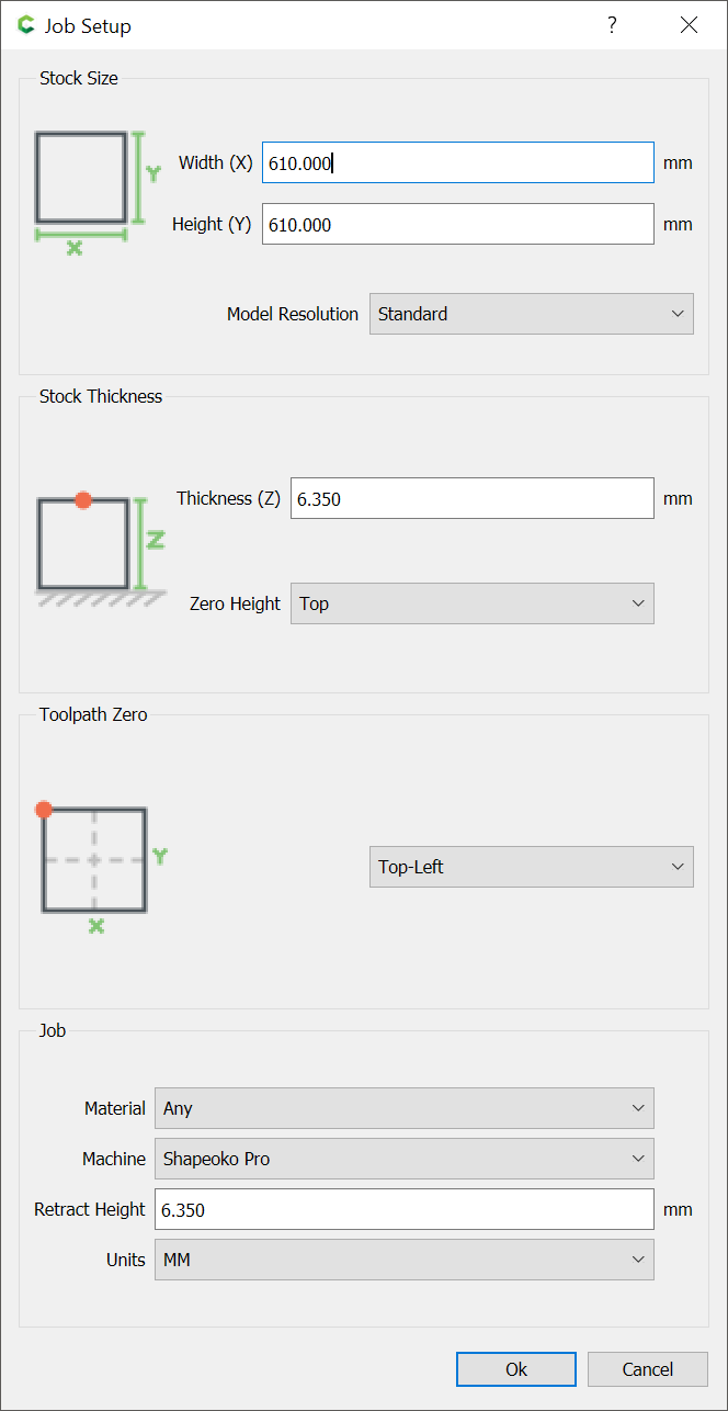
It should be possible to cut strips from a suitable blank of material, one along each axis — so we set up a square file which matches an available blank of material:
Put the origin at the top left corner so that it doesn’t need to be changed.
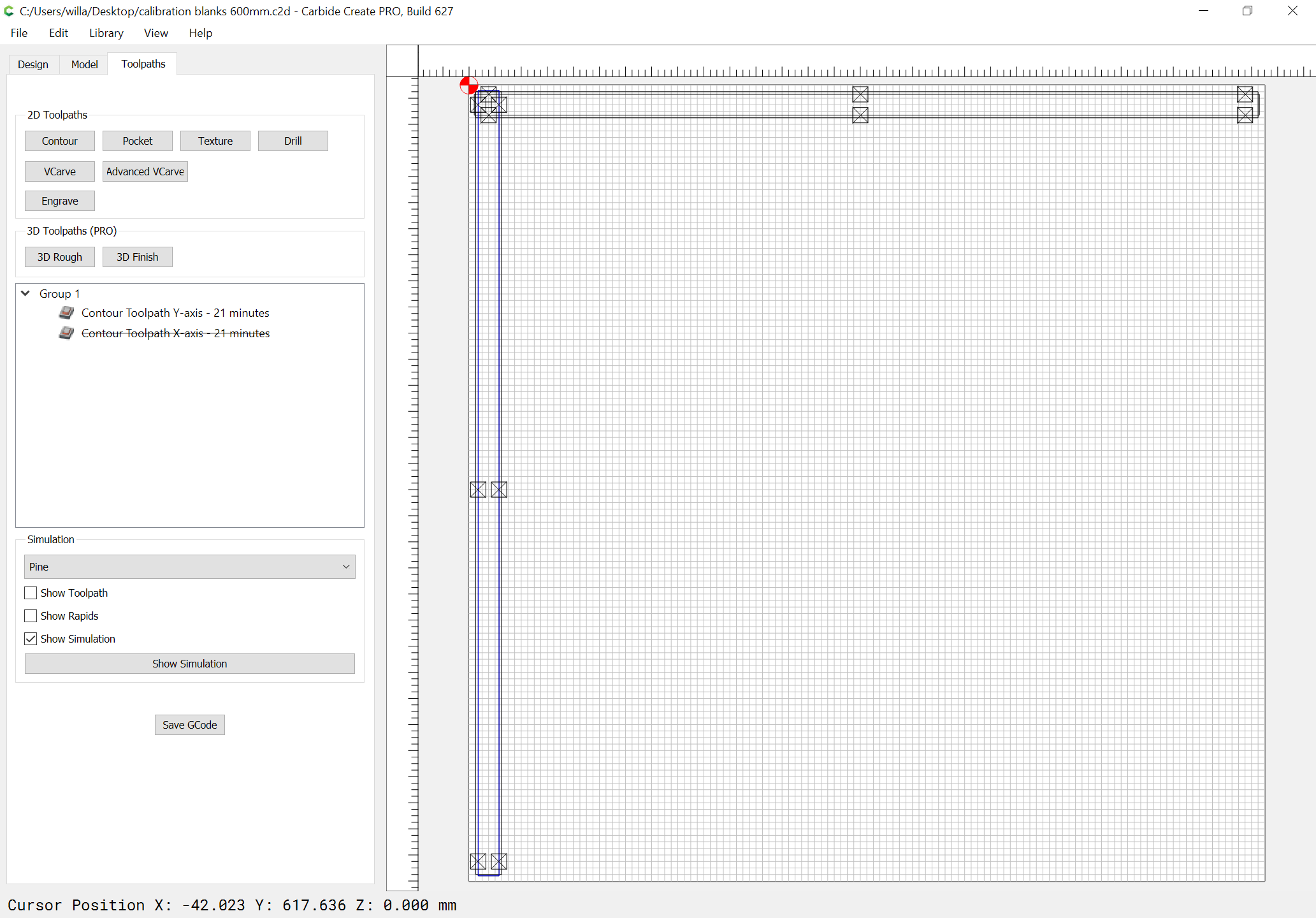
When cutting material from the square, after the first, we rotate and always cut along the same axis of the material so that it doesn’t lose the dimension along what becomes the long axis.
I read an article a while back about calibrating X and Y that said, instead of cutting a shape of some prescribed dimension, measuring, adjusting and repeating, that it was easier and quicker to use a metric ruler as long as possible. Using a V-bit, set X0 at the left edge, jog the X some distance (500 or more mm) and measure with the ruler. One can pretty easily eyeball to a 1/3 mm, so take your measurement and adjust using the normal adjustment procedure. Then repeat for Y.
I know this isn’t machine shop precise, but I work with wood which is also not machine shop precise. But if I’m off by 1/3 mm over 700 mm, I’d say I’m pretty darn close! This is a quick and pretty simple way to get “close enough” for woodworking tolerances.
For Z I will resort back to the normal method and cut to a depth, measure, adjust and repeat.
This method may not be precise enough for some, but for me and what I do, it works!
That’s what I do as well, I have a 60cm steel rule of reasonable precision, I use a narrow angle V bit and the camera on my phone as a magnifier, I can easily see down to < 0.25mm on the 60cm distance which is 0.05%.
As Will points out, measuring over a longer distance reduces the impact of small local errors, backlash, wheel stiction, inconsistencies in belt tooth pitch etc.
A word of warning for OCD folks: measure over a long distance, feel good about having calibrated your machine, and then proceed to making great projects. Do not, I repeat, do not chase your tail like I did for 6 months (well it was for fun and science too), it led to all sorts of crazyness. I did learn something: if you are chasing 0.1mm or less of calibration accuracy across the whole work area and for both small and large pieces, there are a number of things that will probably matter more than a dead-on belt calibration anyway.
My personal takeway is:
do as mentioned above and you’re good to go for pretty much all woodworking projects.
in all other cases, creeping up on the correct dimensions by adjusting the CAM (e.g. “stock to leave” if using Fusion360) is way easier than getting crazy over belt calibration accuracy
Cut one or the other axis, measure the length of the cut part, and adjust based on the math:
measured length / intended length == ratio to adjust steps/mm
The best thing about cutting these lengths is that one can compare the two parts, putting a caliper at one end to measure the difference then allows one to dial in one axis so as to meet the other.