The 2 big compartments are 4" inside by 9" long. Center compartment is 2" wide by 9" long. The height of the handle are 9" high and the fit into the 2 pockets that are cut out.
Napkin Holder Rev 1.c2d (88 KB)
I’ve written about this a bit, see:
and
Hang on, we’ll work through this here and now.
Since the parts will be symmetrical, we arrange them all in a row:

and fix the alignment of the grooves for the bottom:


We draw up the joint in profile:

and draw up the tooling which will be used:
`

Note that this requires that one have a narrow 90 degree V endmill which is markedly narrower in diameter than the stock is thick.

This makes the ultimate toolpath obvious — a No Offset groove separating each part:


(one such toolpath will be necessary to separate each end of a part or pair of parts)
This allows us to begin visualizing the joinery:

It will be further necessary to continue this V so as to have a blind miter — the easiest way would be with a tool sufficiently large to cut this entire height/width, but that would be almost impossibly large for the trim routers folks use (I will spare you the story about the attempt to use a quite large tool which it turns out was not balanced well enough — that Z-axis still squeaks sometimes).
Instead, we draw up a #301 and work out using it as a reasonable compromise.

Putting this in place we get:

which gets us halfway, and duplicating it for the halfway point:

Gets us the rest of the way there — I believe it’s easiest if the Stock Thickness is used as the length for the miter area, so we draw lines of the appropriate length:


and position them to match:

and then assign toolpaths to the depths needed:

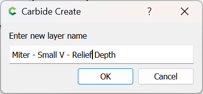
Note that at this point, selection gets a bit tricky, so it’s probably best to create a Layer for each sort of element/toolpath/depth, so in this case:

and the others are at half the thickness:


which previews as:

and should be duplicated to the other end of the joint:


which now previews as:

1 Like
Next we need to draw up the box joints — there are a couple of considerations here, and a prime one is that we will need a tool narrow enough to relieve the material for the narrow V tool, so we will use a #102 (or other 1/8" square endmill) for this.
A second consideration is whether we relieve the tops/ends of the joints — doing so would greatly reduce the voids in the joinery, but also greatly increases the complexity, and moreover, requires the usage of roundover tooling which Carbide Create cannot directly preview:
So, the best option is to relieve by some height — a convenient value to use is the radius of the small tool used, so:

0.0625, so we draw in a line at that point

of the appropriate length (or draw a line of that length and position it so), then align it vertically with the stock:


and assign a toolpath to that depth (or some near equivalent due to rounding):

which now previews as:

We create a new Layer:
and move the line to that layer, then duplicate it and position the duplicate in the correct alignment for the other side of the joint:


which now leaves just drawing in the profile for the box (finger) joints, and creating the geometry to cut them.
Drawing in a rectangle to represent the profile of the box joint we get:

Since we are using a 1/8" tool, we may use any width greater than that for the joints — all the possibilities have various tradeoffs, but we will try something which lines up with the grid, since that lends itself to simpler working with the geometric elements.
The first consideration is we need a central channel as narrow as the tool, which reaches past the stock by at least the radius:

and then we will need alternating rectangles which each describe a void for the opposing box joint to be cut into — but, if the rectangles are made at this size, a tool will not be able to reliably fit into them, so we instead draw in some circles to describe the tool in overhead view:


as well as a square to describe the movement along the center:

and then we connect the dots to draw a polyline which will allow us to assign a No offset contour which will cut the joinery:


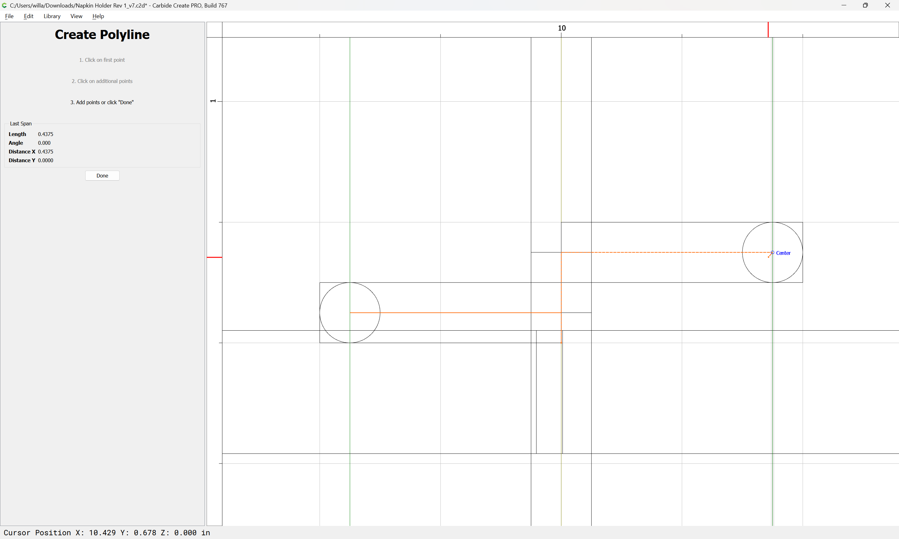


Done

This polyline may now be replicated as needed:


and then joined so as to make a whole:

Yes

which may then be aligned with the Stock:


and assigned a toolpath to the correct depth:

which shows the joinery:

(and that arguably, we only needed 10)
which looks like it will work, so now we need only:
- duplicate the joinery geometry to each end and mirror as needed
- rename all toolpaths (and re-assign them so that they are each associate with the appropriate layer)
- reduce things so that only two parts are cut at a time
- add the toolpath for the groove
For an example of a project done with similar joinery see:
Note that when that was dry-fit as a test, I was subsequently unable to get it apart to apply glue.
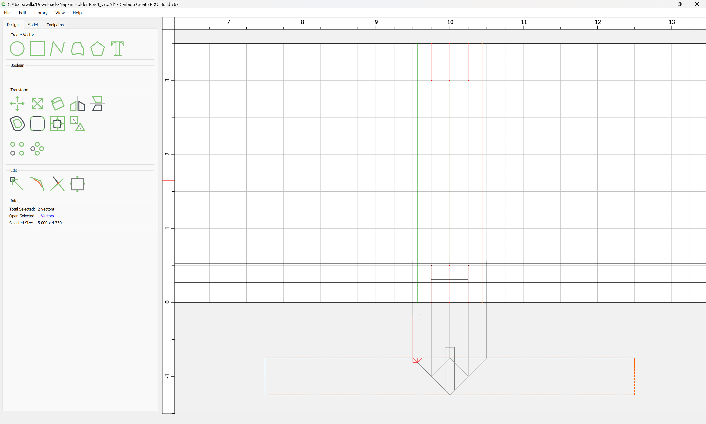
With everything on a appropriate layers, one can hide all but the joinery:

Select and Duplicate:


and fix the layer association and drag things into alignment

Then tidy up by removing elements which are beyond the stock area:


For the joinery, select it:

go into Node Edit mode:

Delete the nodes beyond the Stock area:

and Delete


Done

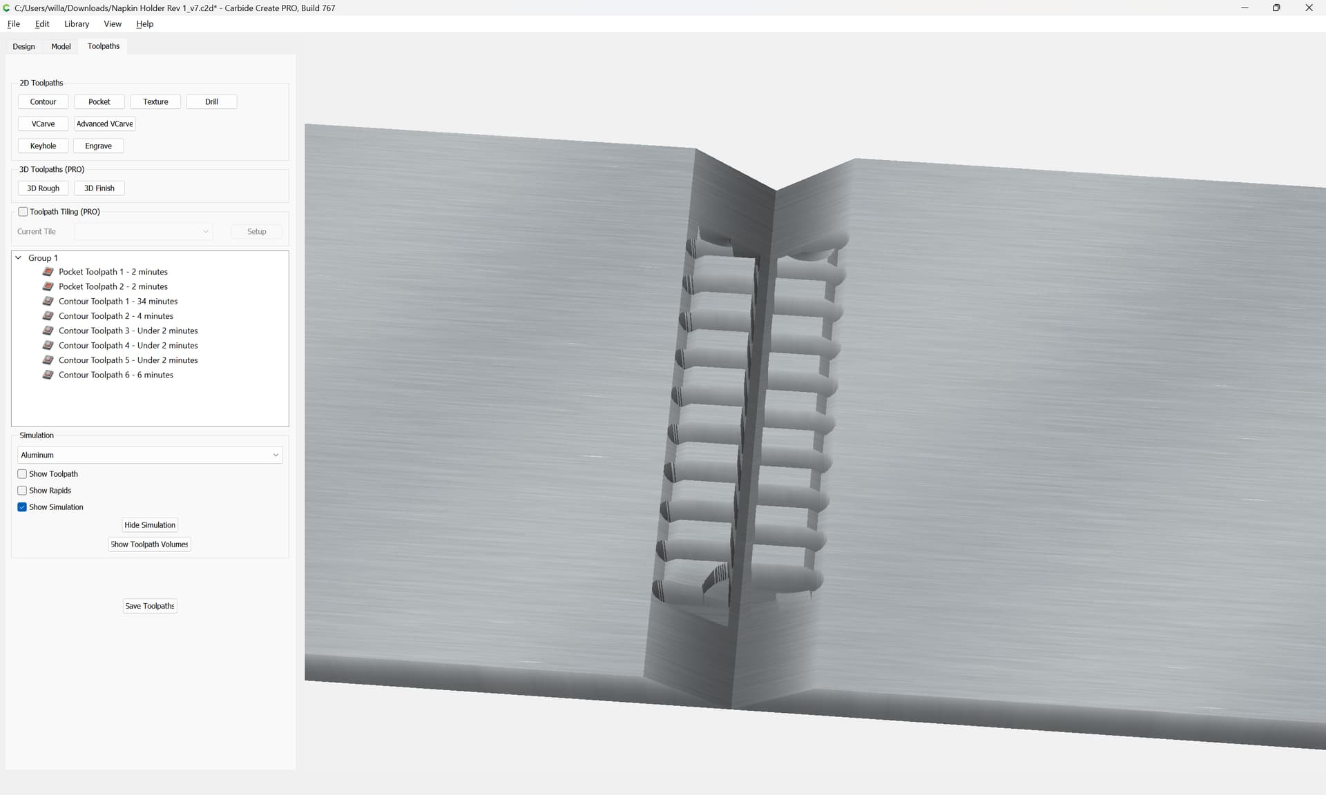
Attached as a v7 file.
Napkin Holder Rev 1_v7.c2d (80 KB)
Final considerations:
- if using a belt-drive machine, make sure that you have calibrated for belt stretch:
-
do a test cut/fit first (I’ll spare you the story of the all-nighter chiseling a similar joint to make it fit)
-
the 1/8" tools which I use for this sort of thing are a 90 degree 1/8" V endmill made by Kyocera sourced from Drillman1 on eBay, and a 1/8" downcut tool from Carbide Tool Source
Thanks you very much. Took me 8 hours to try and follow along, but I think I got it. I’m going to try and cut it tomorrow night.
Our pleasure!
Please let us know how the cut turns out!
If you have any questions, could make a note of any aspect which was particularly difficult to follow, please let me know — I believe this is the version I’ll be writing up at:
One final thing I just noticed — there aren’t any dog bones on the pockets for the vertical handle/dividers — you’ll either need to square them up w/ a suitable chisel or use a rasp or file to round the ends of those parts so that they will fit.
I’ve purchased the 1/8 endmill from Carbide Tool before. I’m having a hard time finding the 1/8 90 degree v bit. Do they make a 1/4 shank set up like your 1/8 endmill? Does it only come in 1/8 shank? Been looking through Ebay have trouble finding it.
I believe it was this:
Hopefully you can find a more affordable listing — drillman1 was who I bought from, but apparently there’s a new username?
How do you make dog bones?
I got the bit ordered.
Dog bones are a feature for rectangles.
To add them to the fingers above it would be necessary to draw in a brief 45/135/225/315 degree movement the distance necessary to create the dogbone.
I’ve done them in other joints, but I find them unattractive and an unnecessary complication (says the guy who can’t get the afore-mentioned dry-fit pencil cup apart).
c.f.,
This topic was automatically closed after 30 days. New replies are no longer allowed.