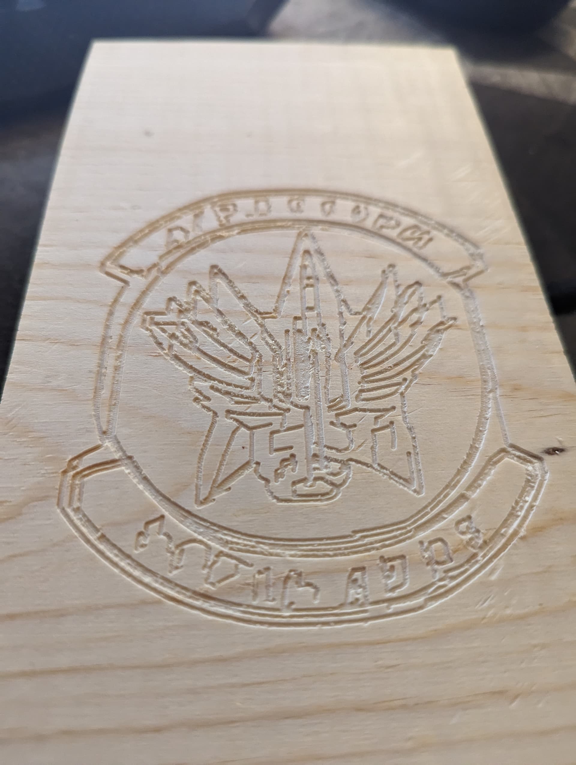
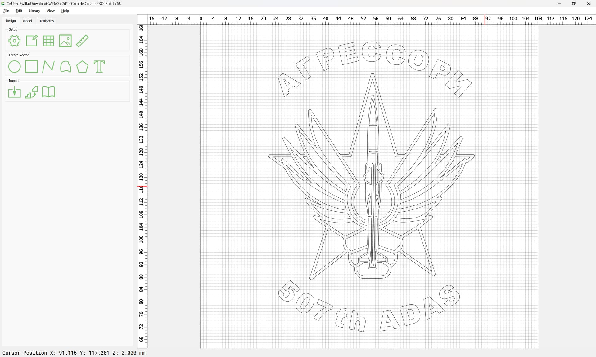
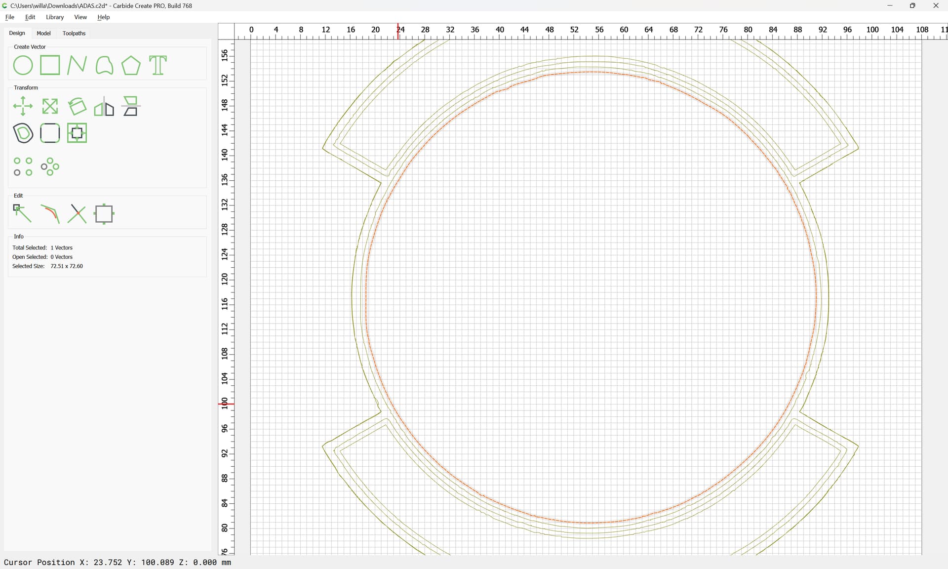
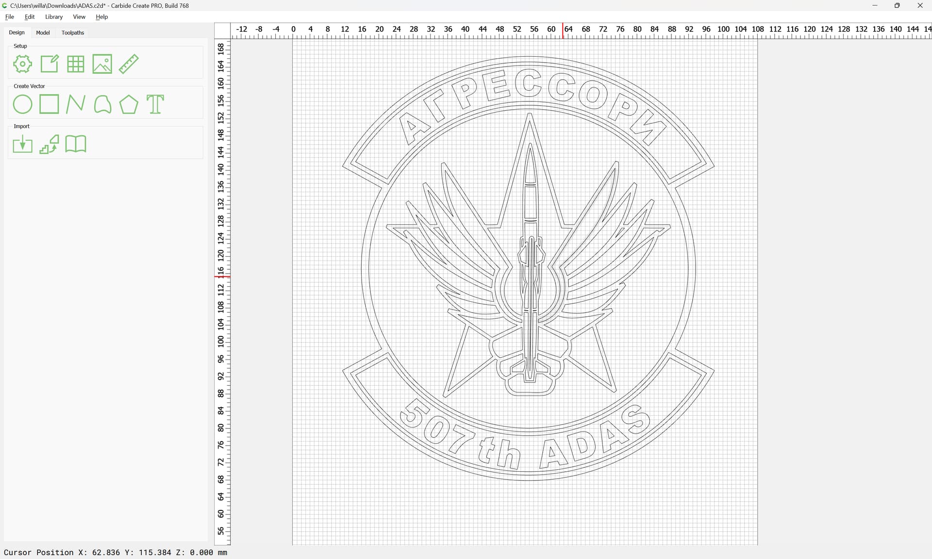
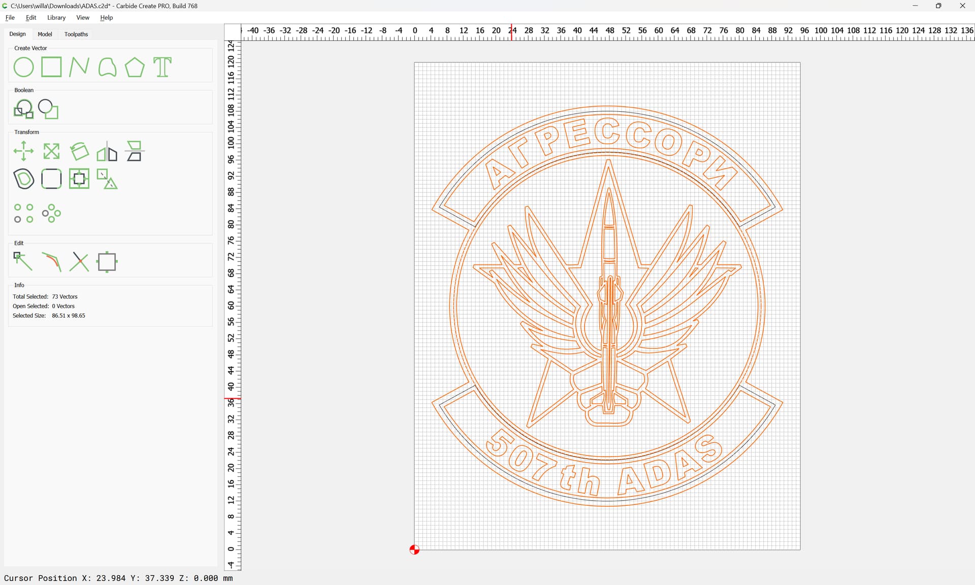
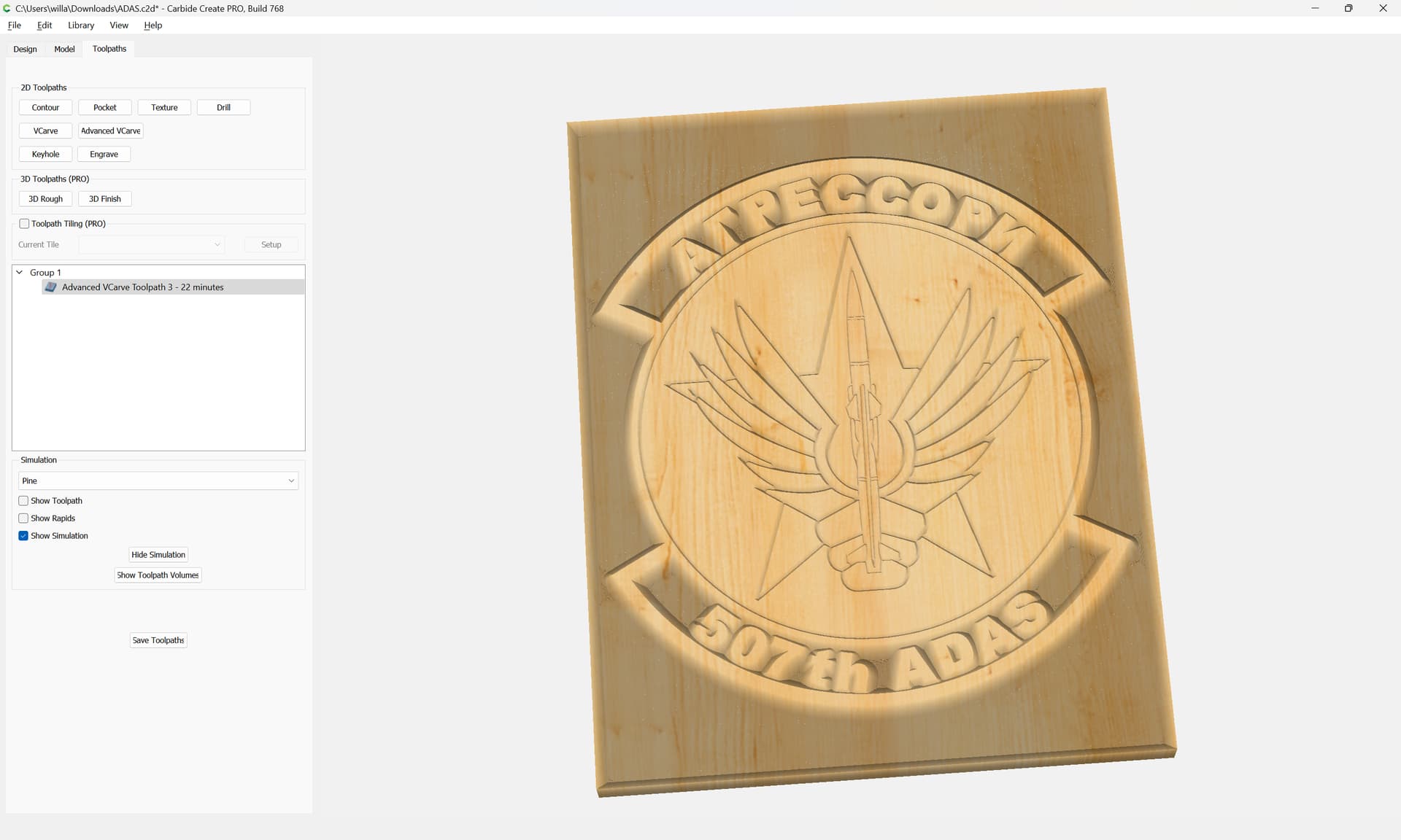
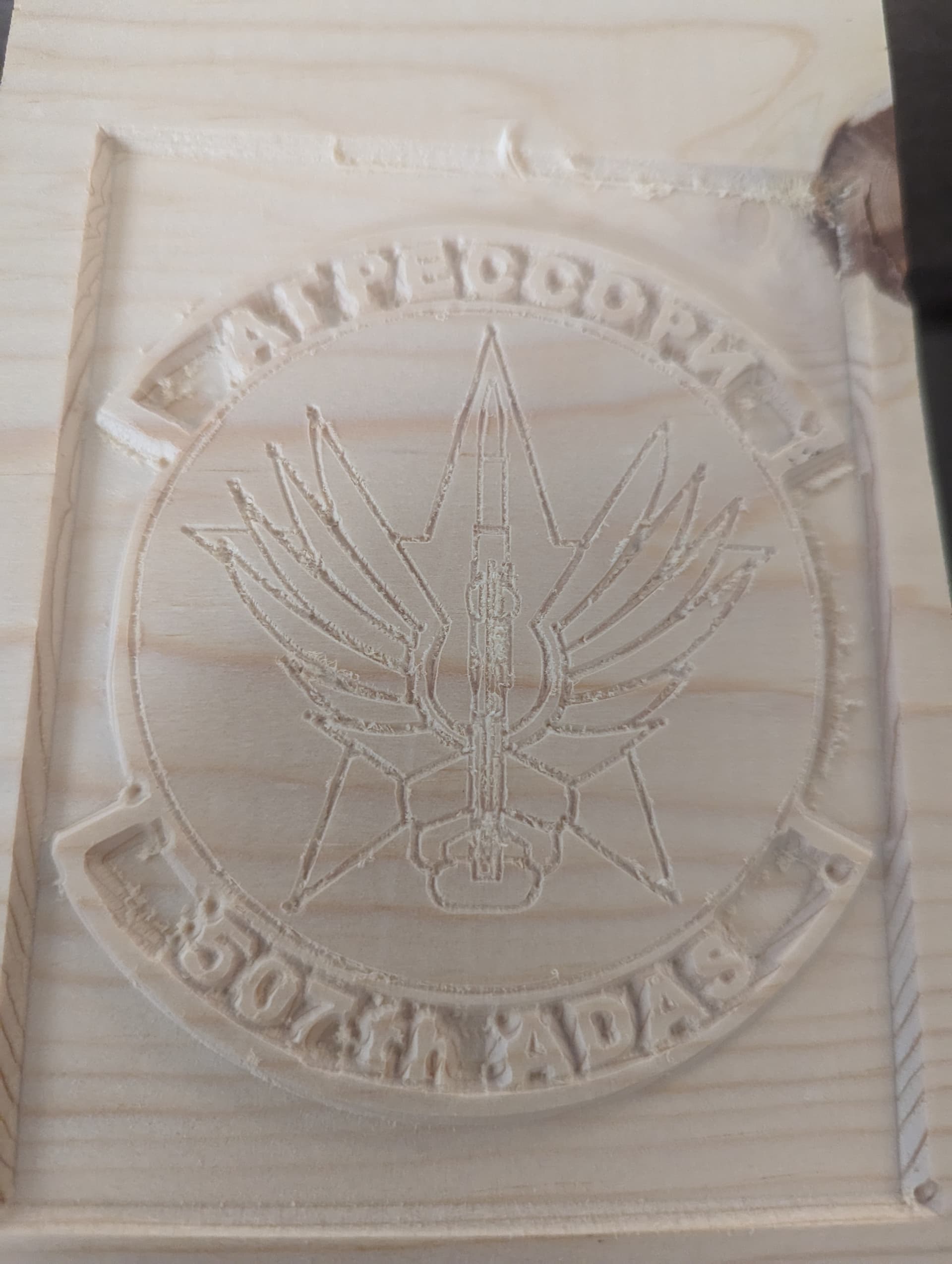
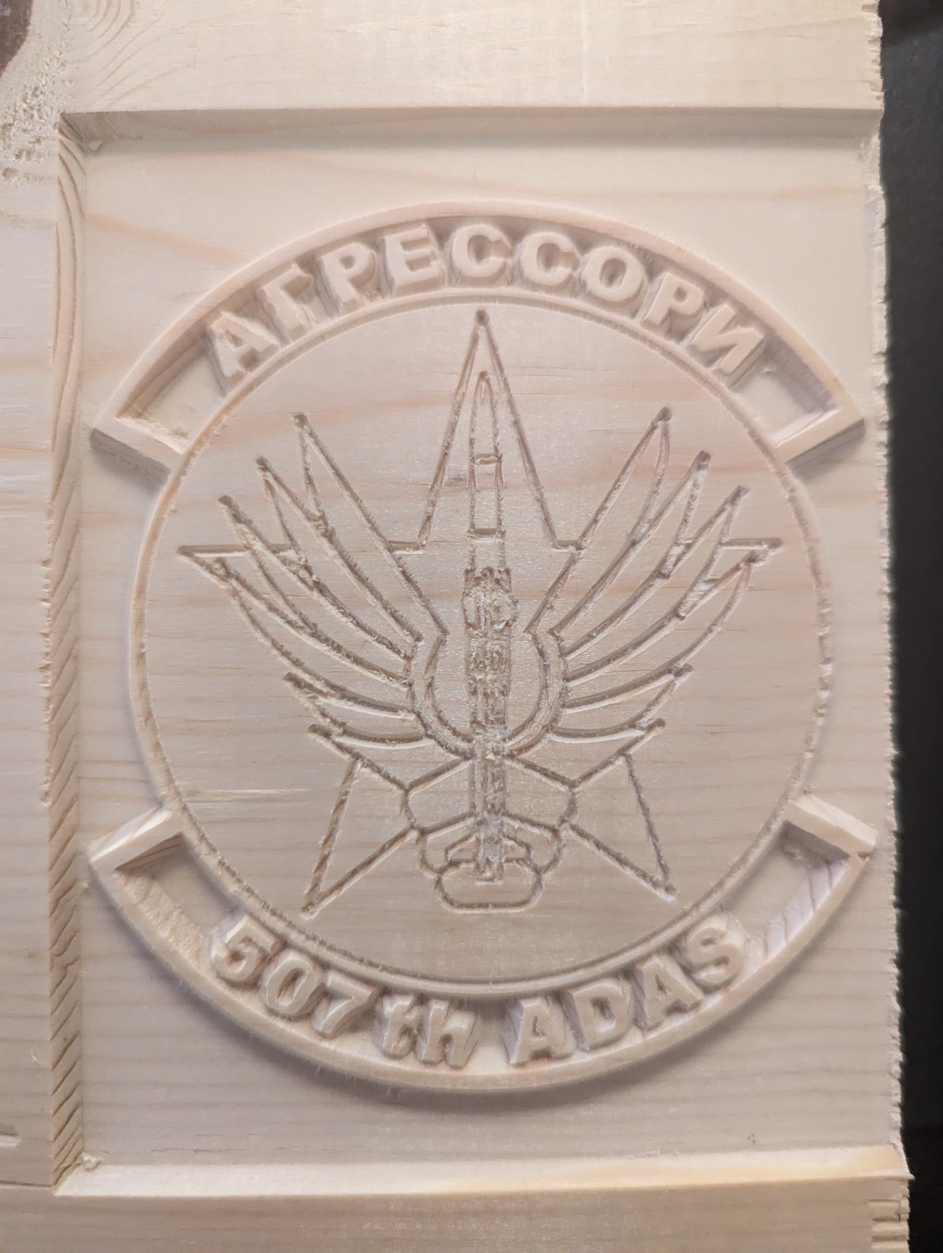
Still learning how to tell the machine what I want it to do. Any advice on how I got from my simulation to finished product? Not sure if motion redrew the paths or what happened. End result looks like I drew it with my left hand. Using a Shapeoko 5, 60* V bit, Carbide 3d free version.
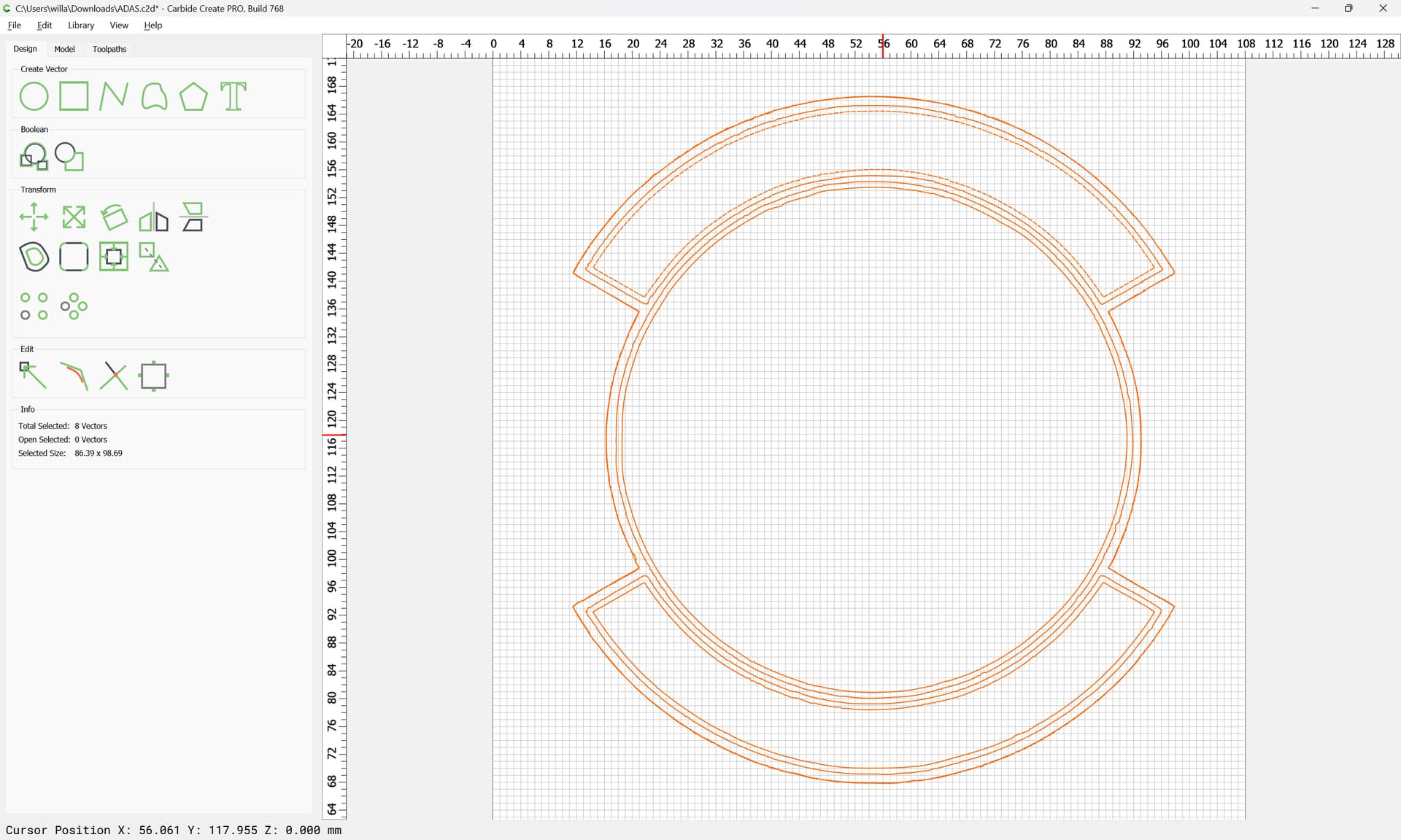
You did not say what machine you have. Looks like you have mechanical problems. Like the circle around the patch is round in the simulation but is not a perfect circle in the actual carving. If you have an SO3/4 check all your v-wheels and belt tensions. If you are using another machine with ball screws check that al your bolts are tight. Some of the ball screw machines have screws that come loose that are the bearings for the ball screws at the ends.
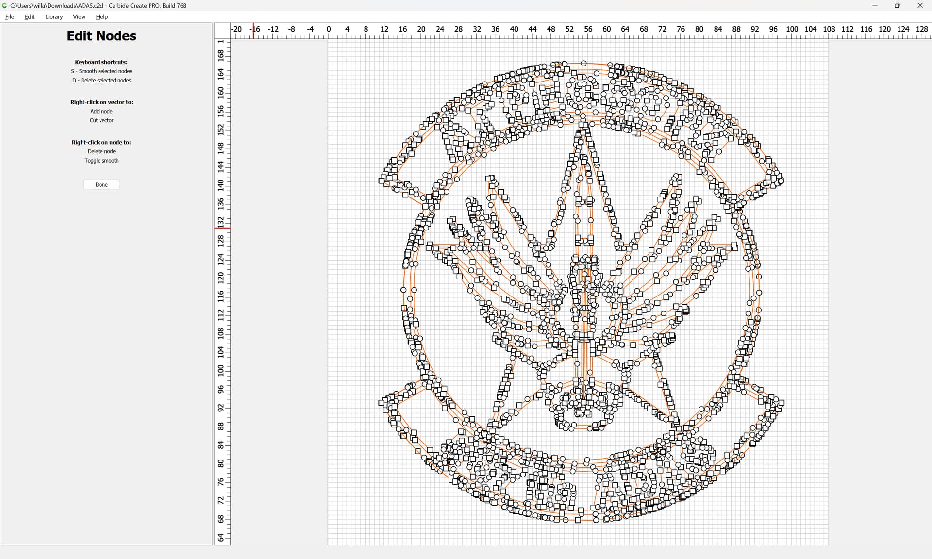
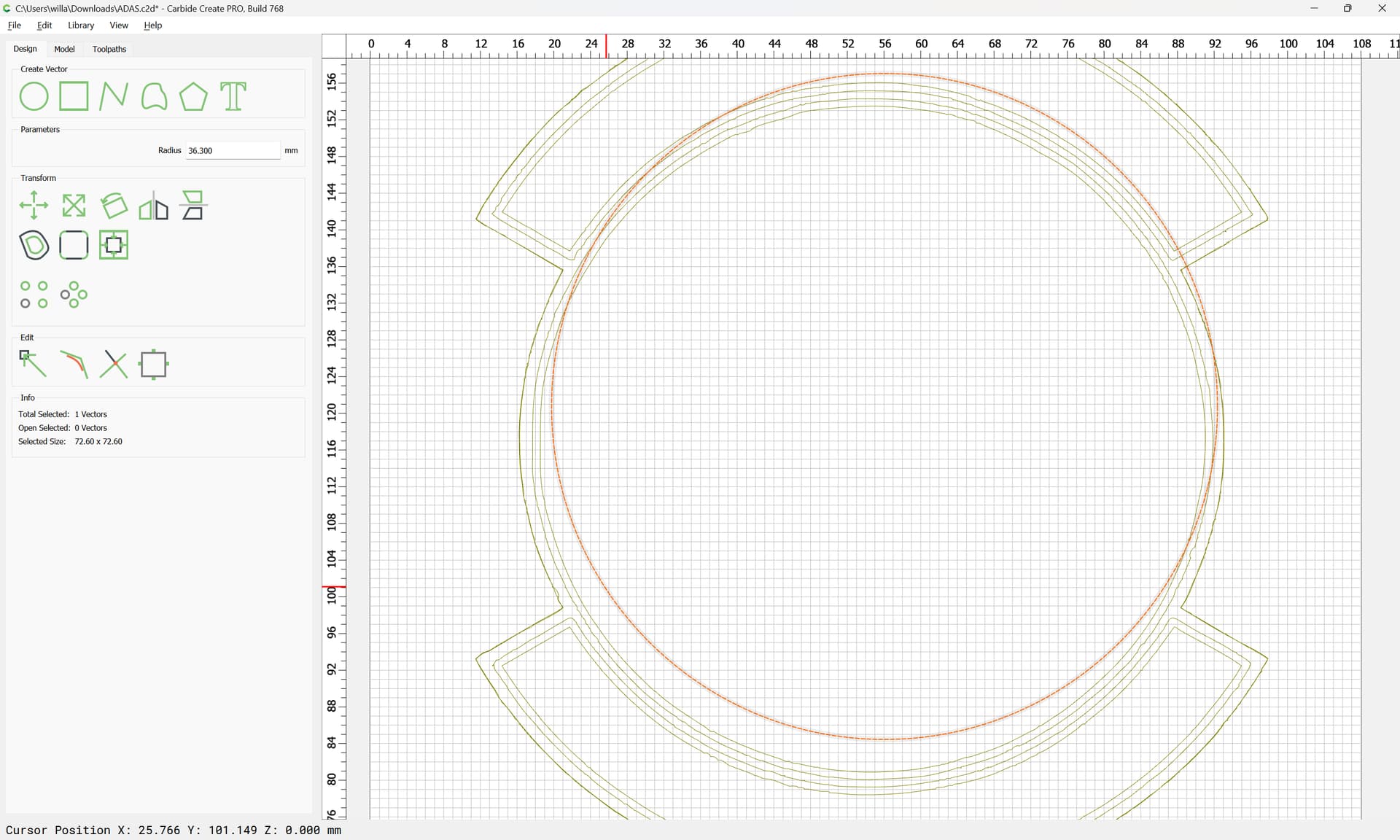
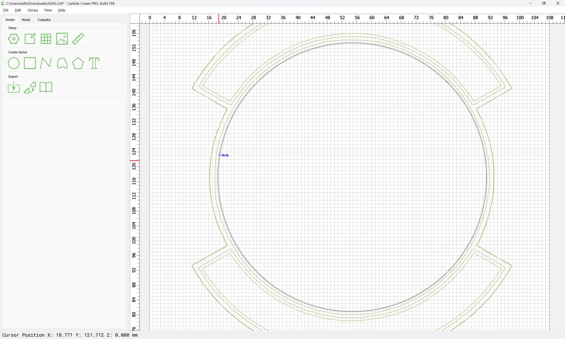
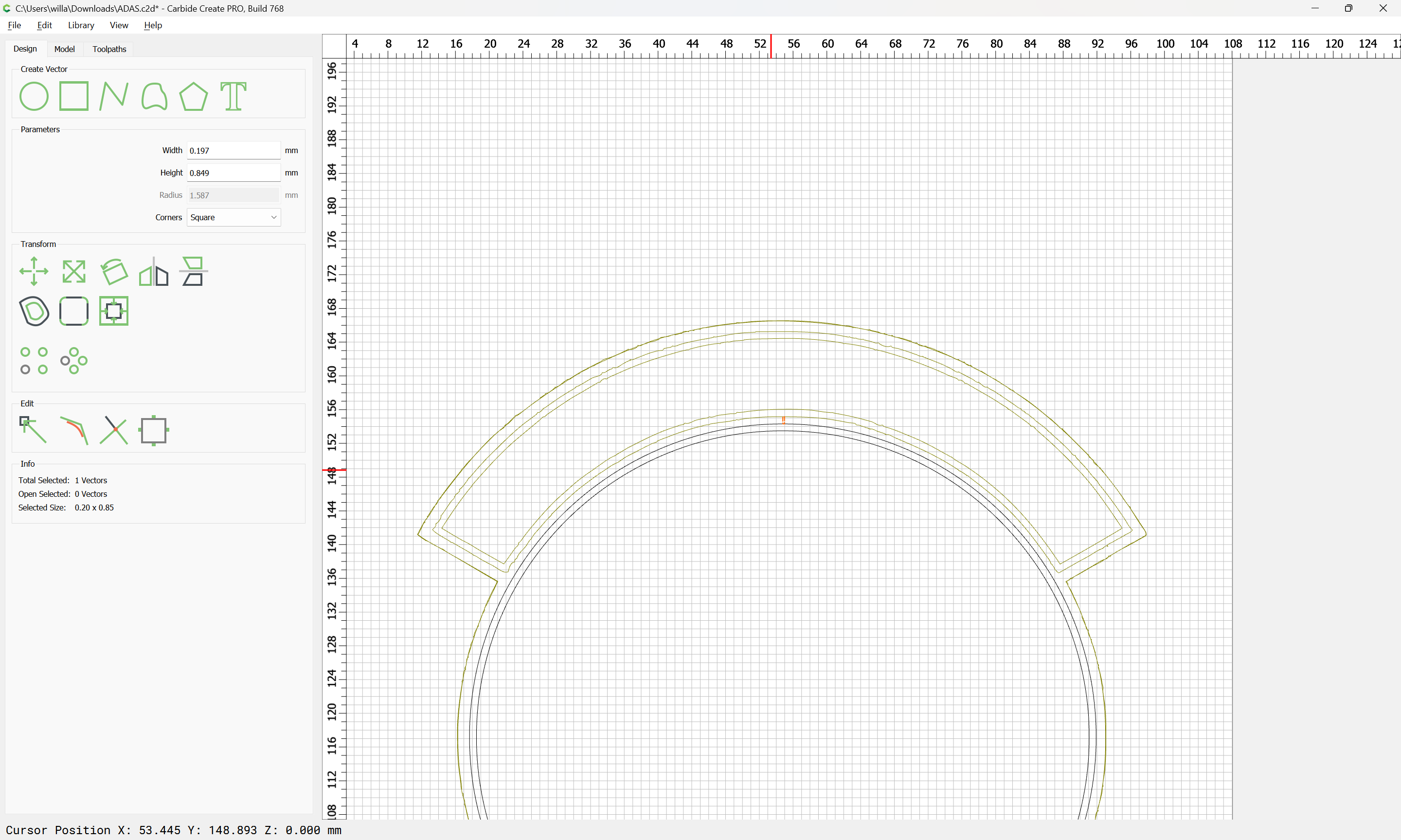
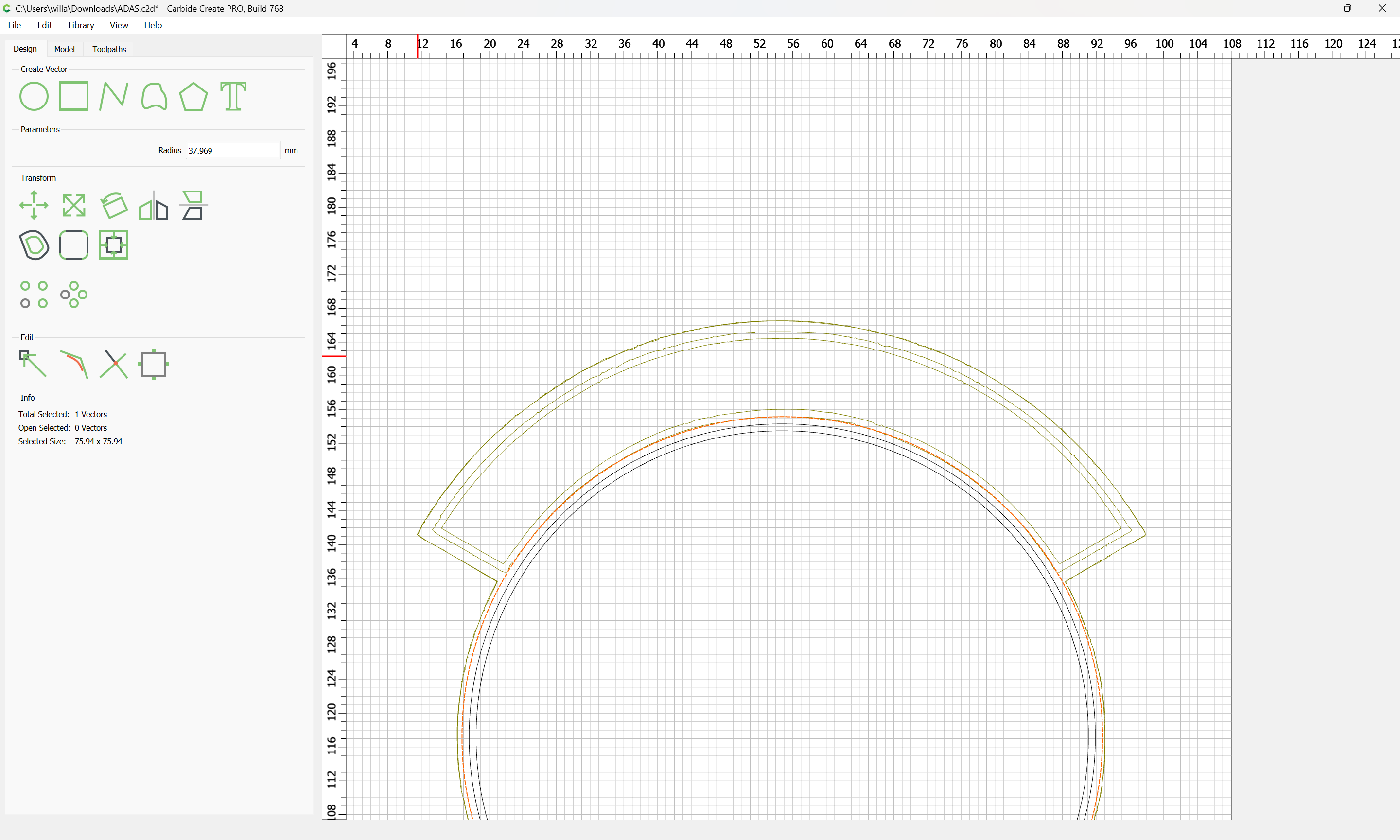
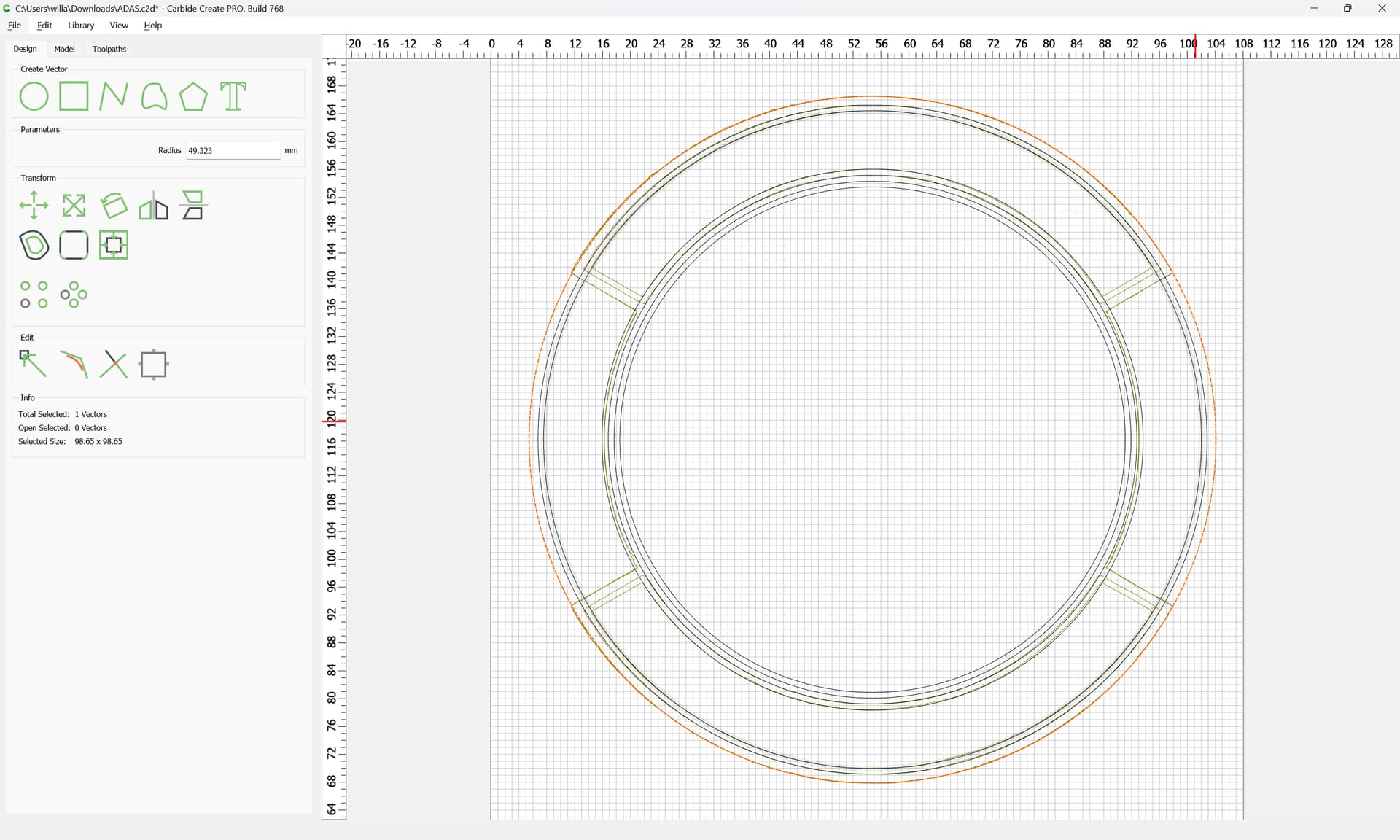
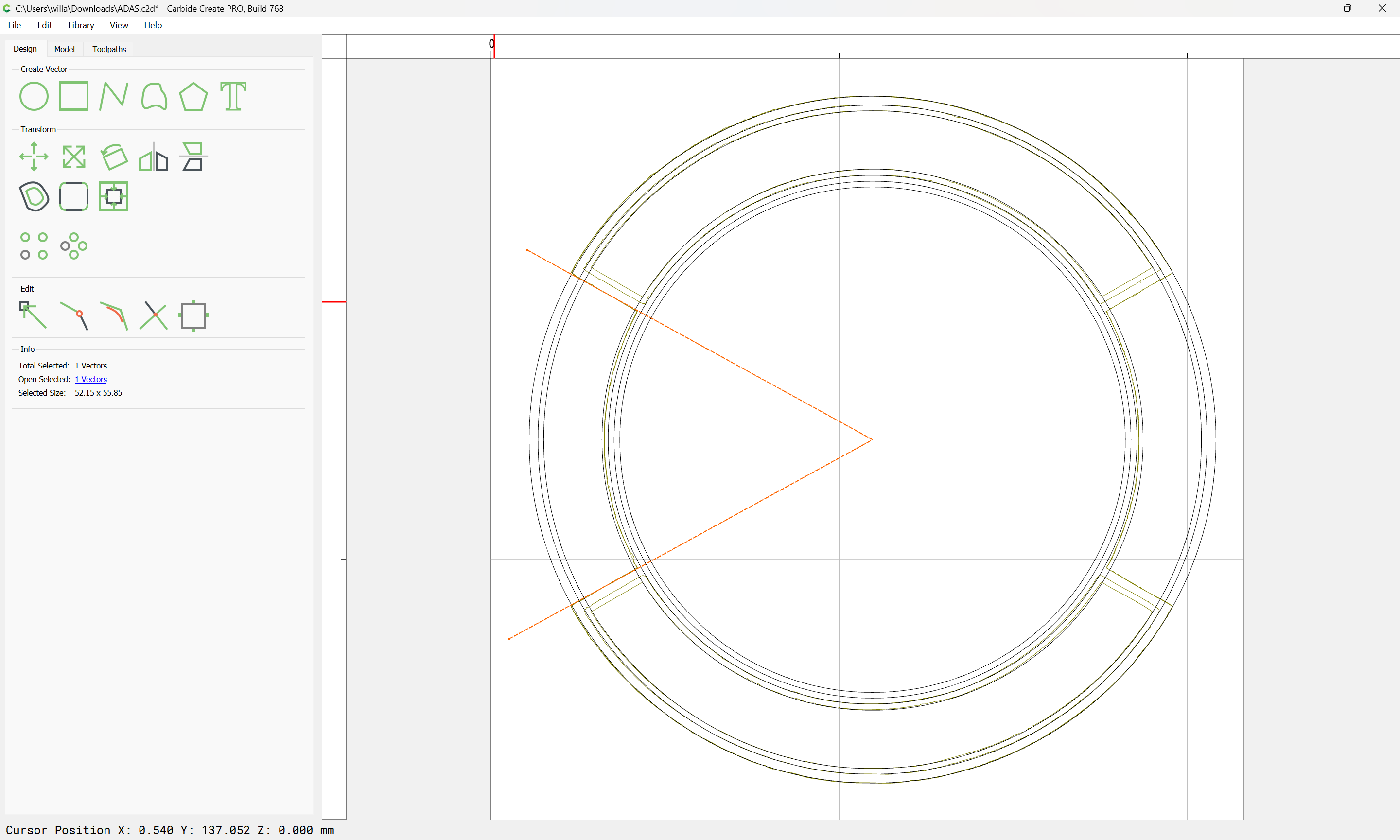
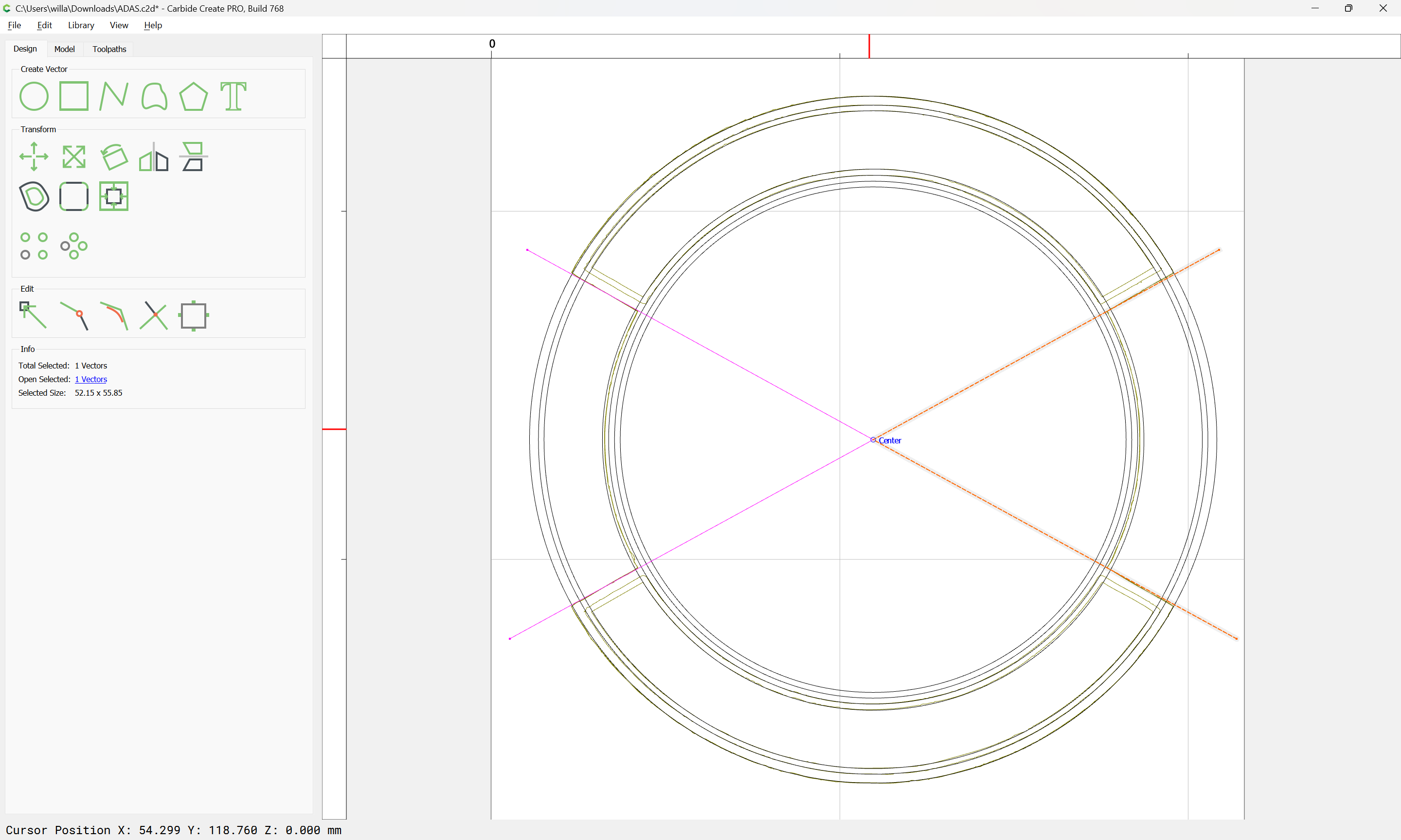
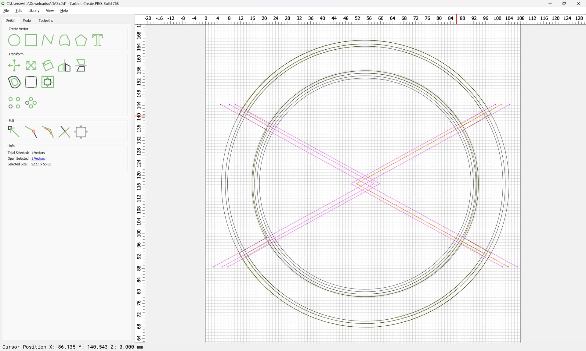
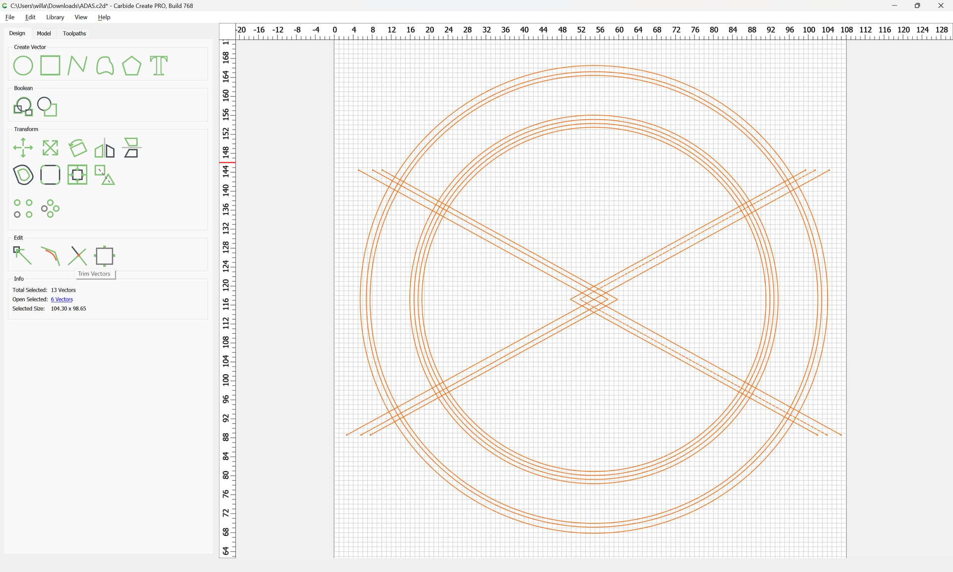
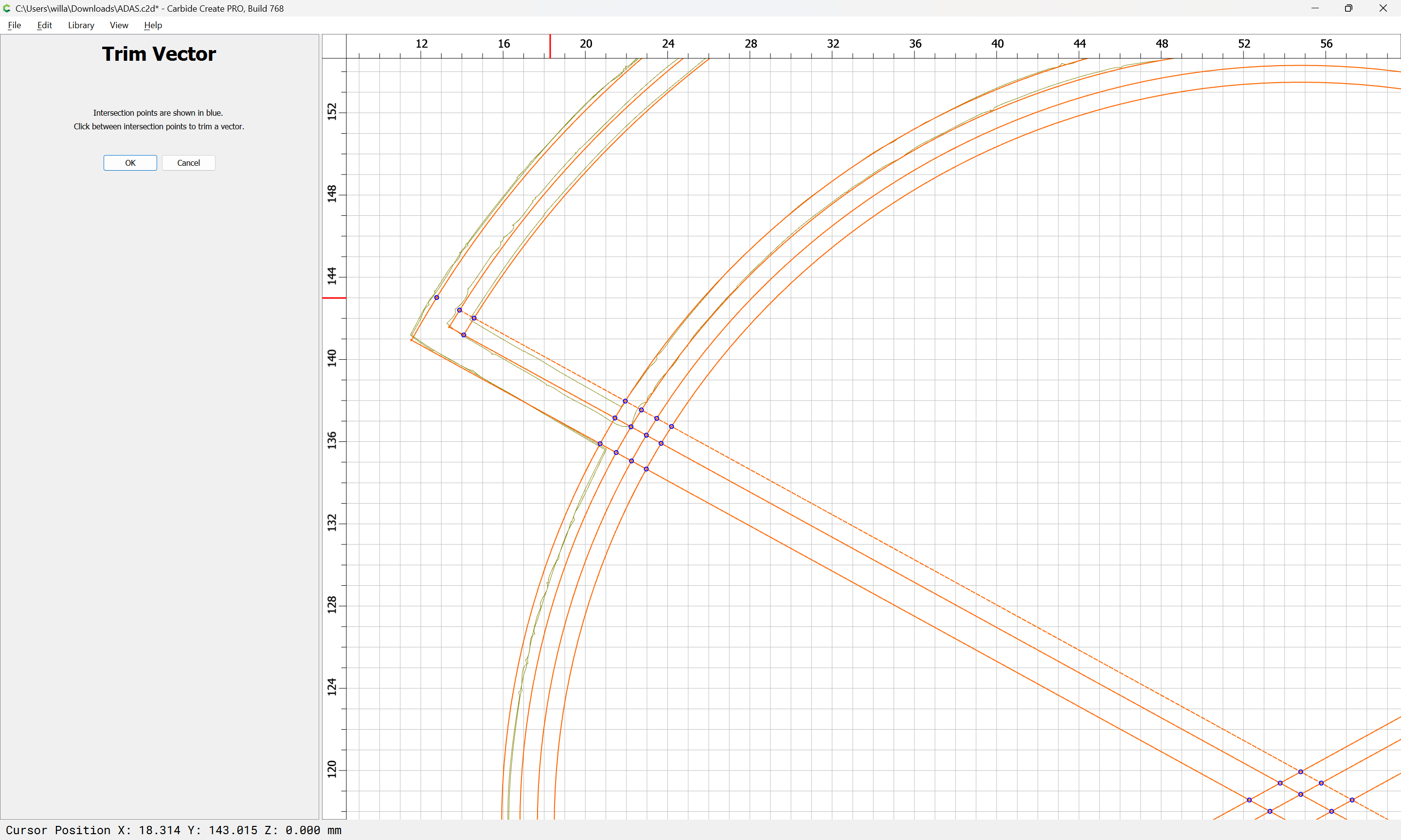
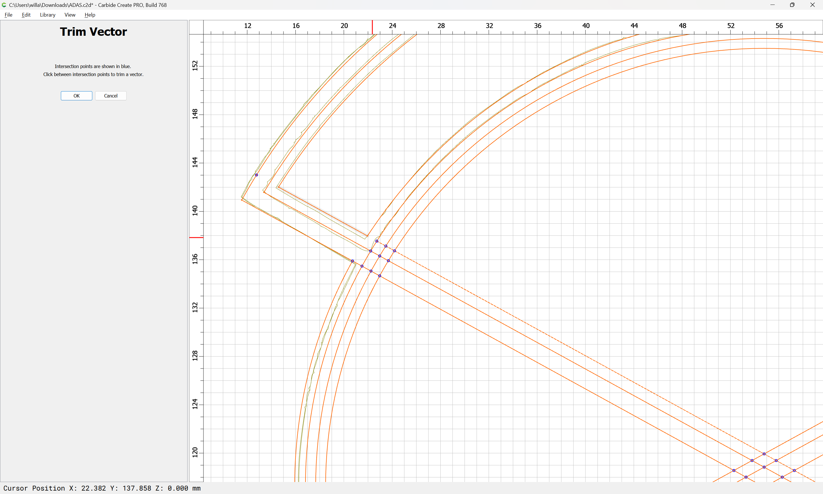
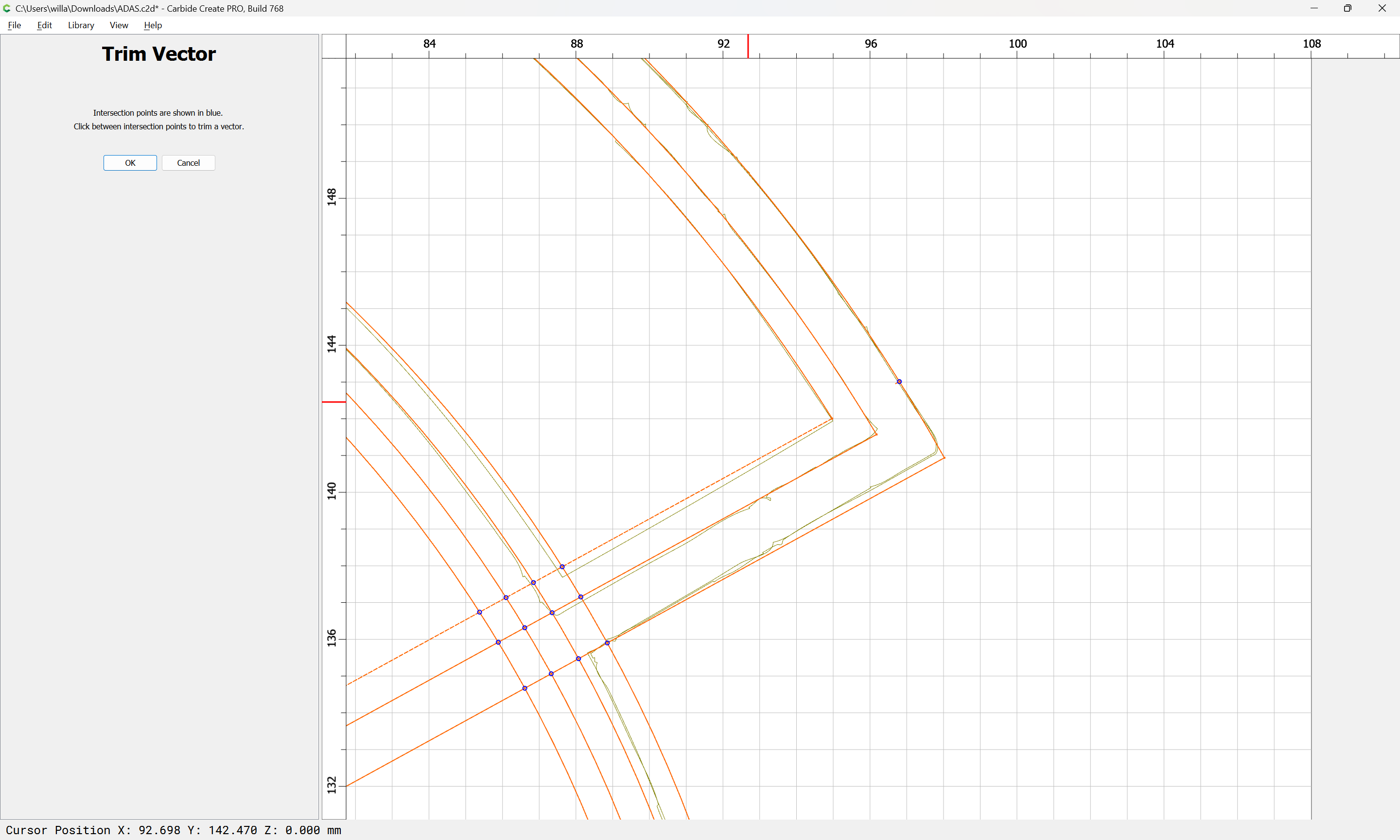
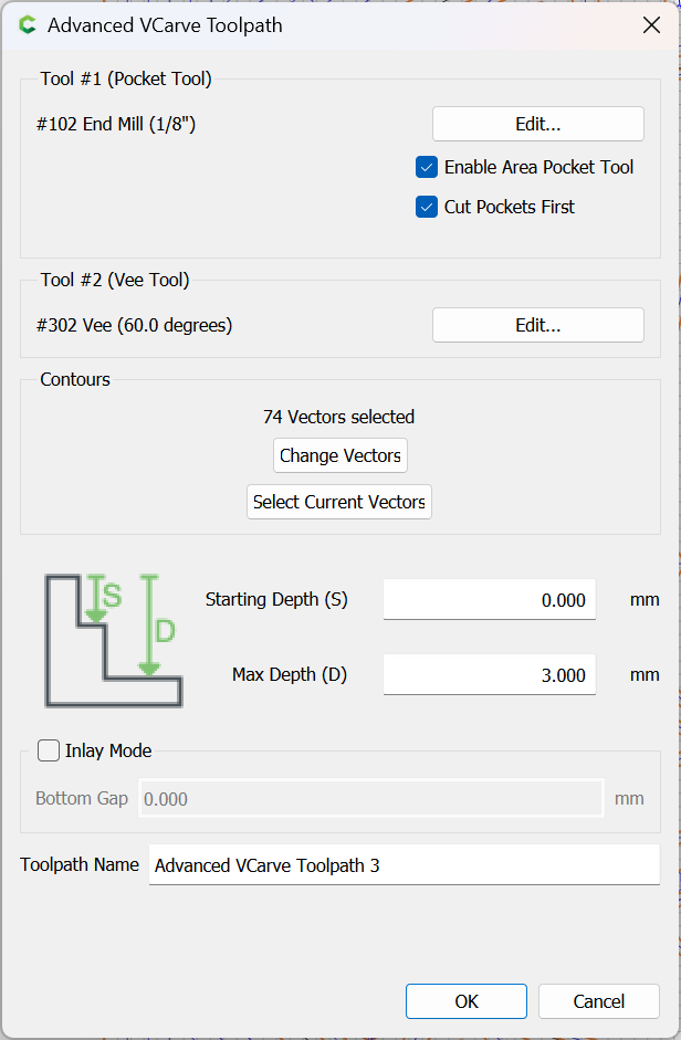
A look at your file you are doing a contour with a vee bit. Why not do an advanced vcarve and/or simple vcarve. I disabled your tool path and did an advanced vcarve with a 15 degree vee bit and a 1/32" end mill. That did result in 400+ minutes but you could increase the end mill size to get the carve more reasonable.
Sorry it’s a SO5. It’s pretty much my first hack at a cut, so I was just trying to draw some lines as a beginner project. Didn’t think it was that difficult to just trace but was shocked at the outcome. Will check the tightness of everything, but it’s recently assembled.
60* is the steepest bit I have except for some amazon knockoff brands but I’m afraid to use them until I got comfortable adjusting feeds and speeds.
Since it is an SO5 and just assembled you might want to talk to support. You are definitely having some kind of mechanical problem. CM or CC does not change the tool paths to look like your actual output. Good Luck
Everything seems tight. I jiggled all the ballscrews and moving pieces but nothing has any significant play. The Y axis ballscrews have such a tiny amount of play I can’t imagine it actually impacting anything, and I don’t see where I can tighten them up to prevent what little play there is. I’ll have to reach out to support and see what they say.
To mechanically check the machine, power up, install a 1/4" probing pin, jog to the center of the machine, then grab the tip of the pin and try to shift it — it should be rock steady — if it isn’t, investigate and check where things are allowed to move.
A few other considerations:
are the tool/collet installed correctly? Make sure that stickout is minimized
wood quality — try surfacing off the material
toolpath options — for smaller designs use a more acute tool
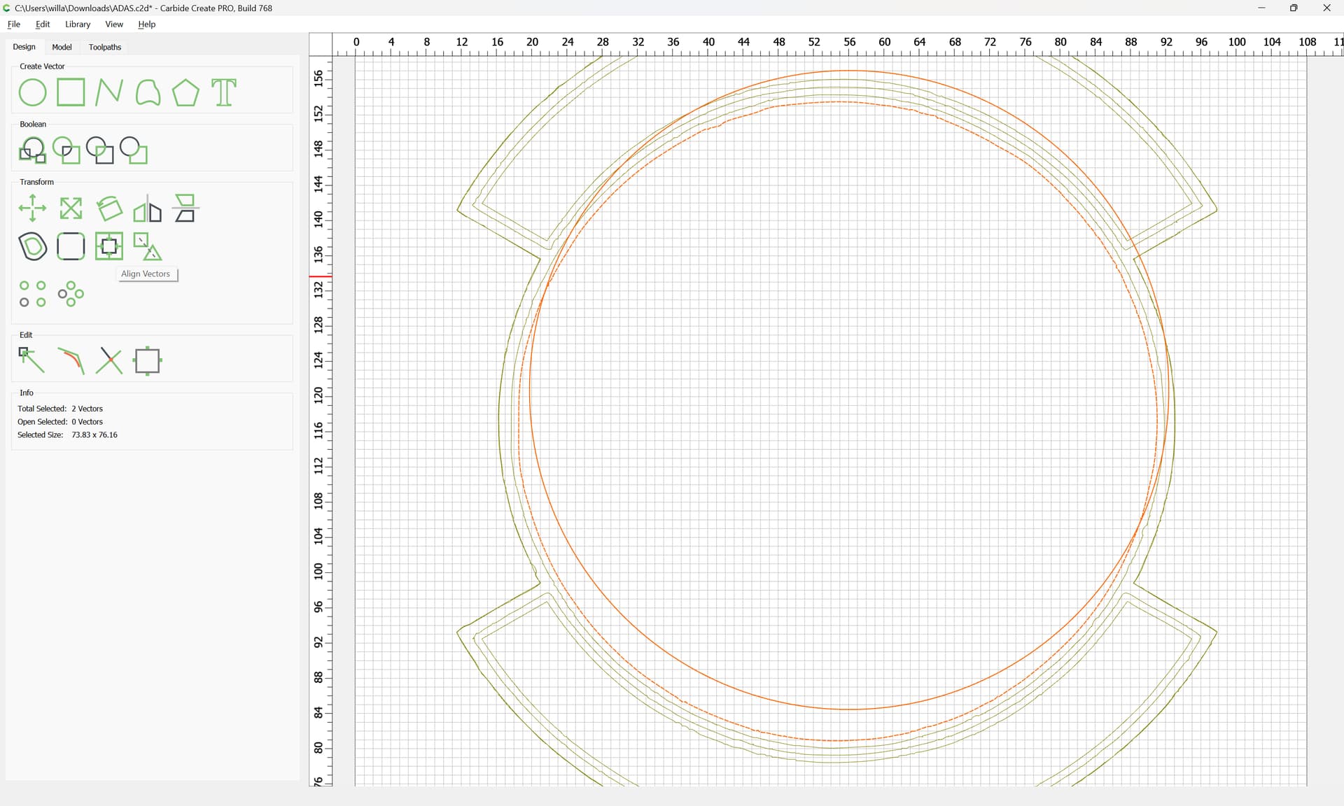
figure-ground reversal — your design is a bunch of shalllow lines, many of which are redundant for describing the insignia
I didn’t see a probing pin in the kit, so I just used a bit. When I move it to the middle there is very minimal movement in the X axis of the router carriage. I can barely see it move, but can hear it move or quietly click. Not sure how to tighten that, will have to dig into it. It’s fairly solid just trying to move the bit with my hand. I can push the gantry and overpower the ballscrew motors, but it takes a bit of force and I’m not sure that counts as actual play.
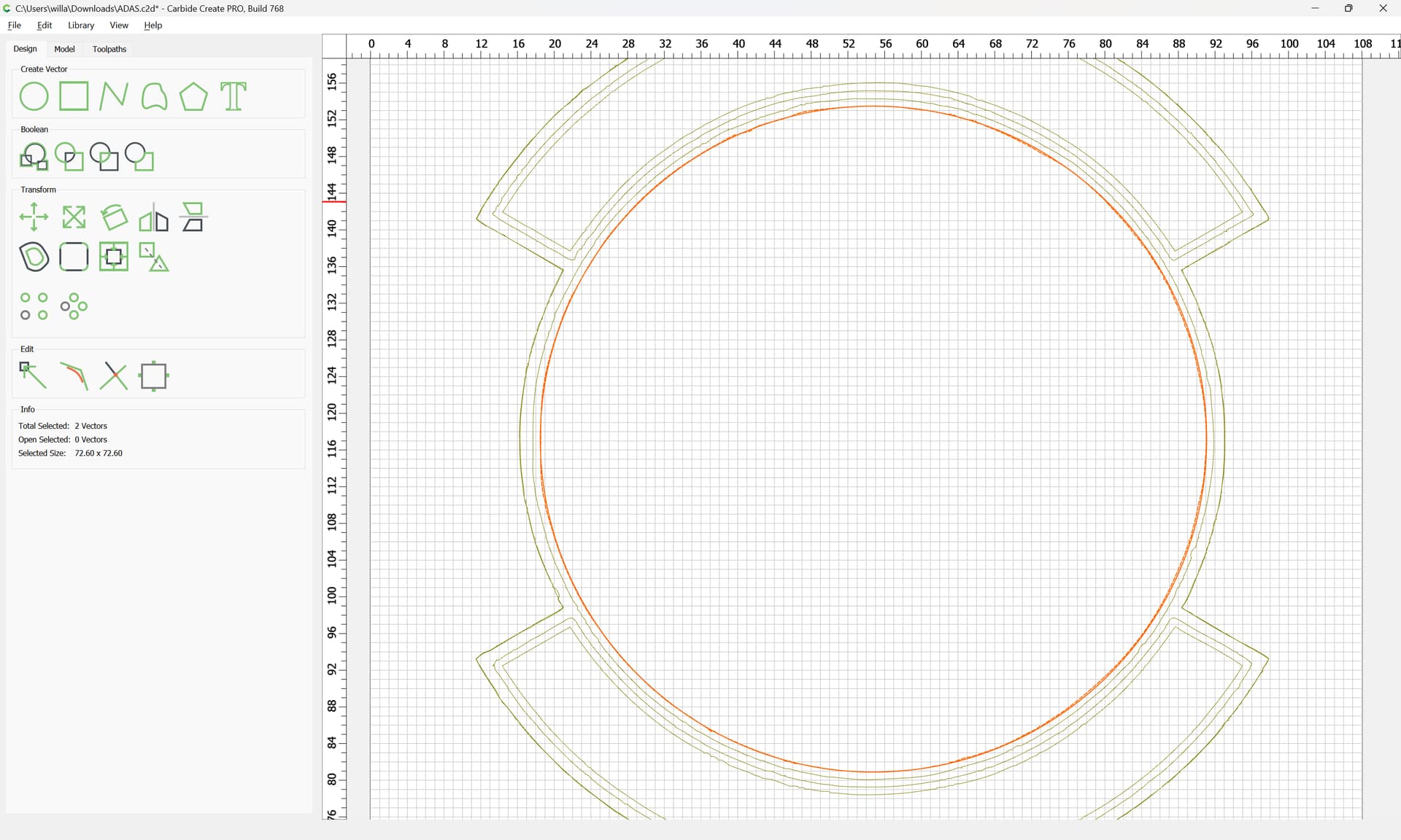
I recut the file you gave me and it’s a lot closer to the original idea, but there are still some issues with uneven widths on the arcs and then other artifacts that aren’t on the simulation you provided.
I would assume it’s an issue with the machine because having a simulation that doesn’t actually simulate the end product seems a bit worthless. I’ll poke around the machine a bit more today and see if I can find a tightening guide for things to check.
The movement troubleshooting guide seemed to clean things up quite a bit. There were several loose fasteners. I did strip one of the screws mounting a motor to the Z plate, but below is with three screws holding it in. I think the remaining issues would likely be cleaned up with better wood or doing an initial surfacing pass to ensure its all level before start. Thanks!