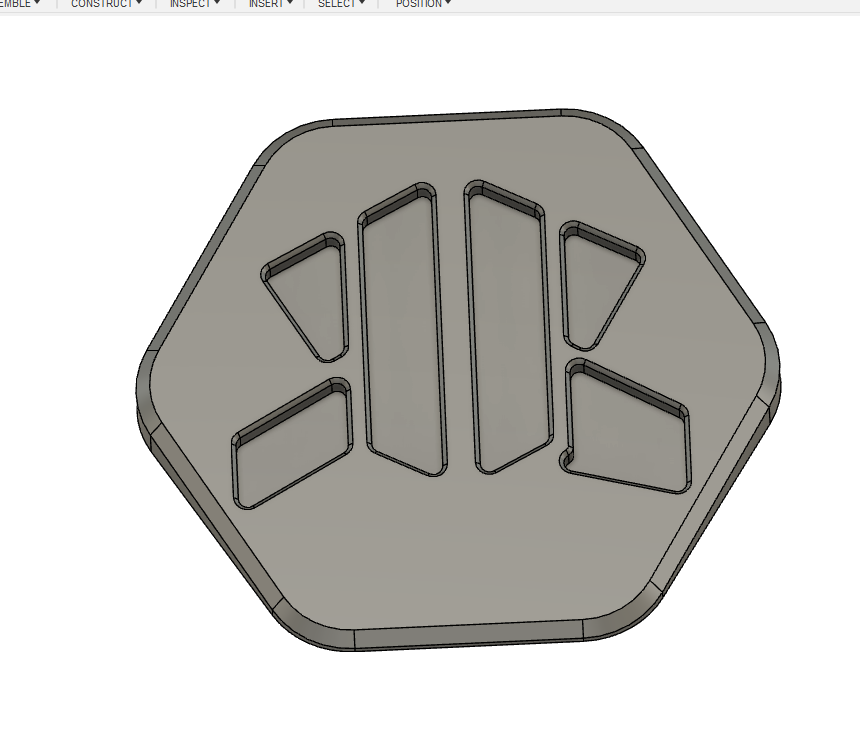
so after doing the demo project on my new Nomad3, i figured it was time to step it up a notch, and i recently came up with a logo design i really like, so i figured it was time to create a maker coin, and add my logo to it, and that would be a decent first project of my own creation.
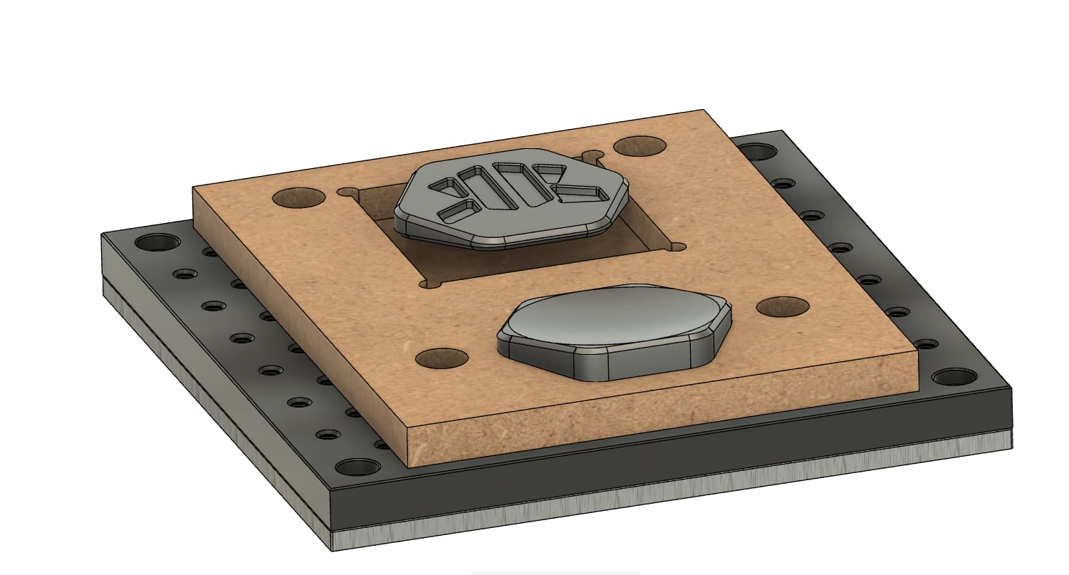
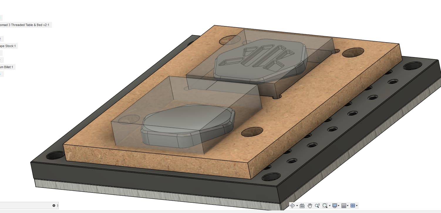
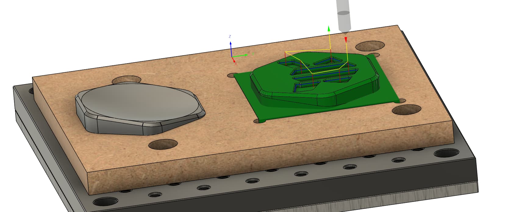
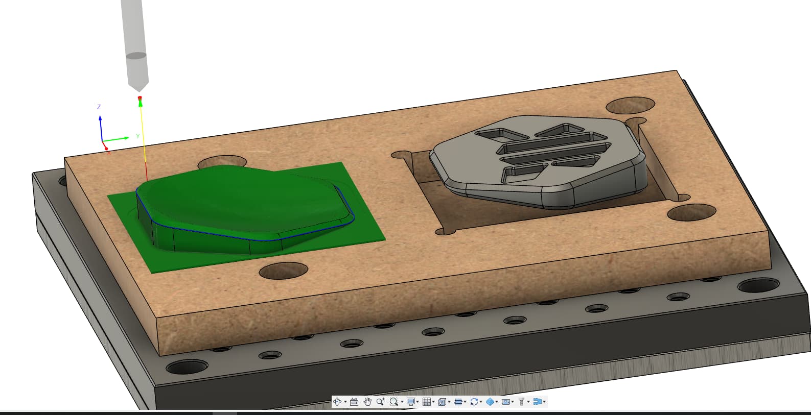
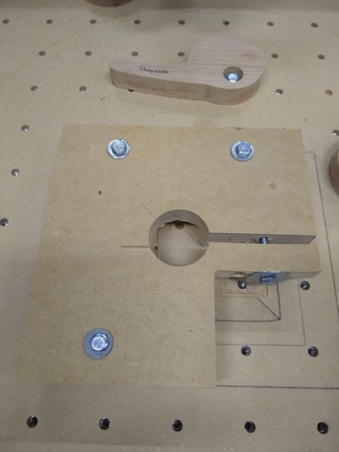
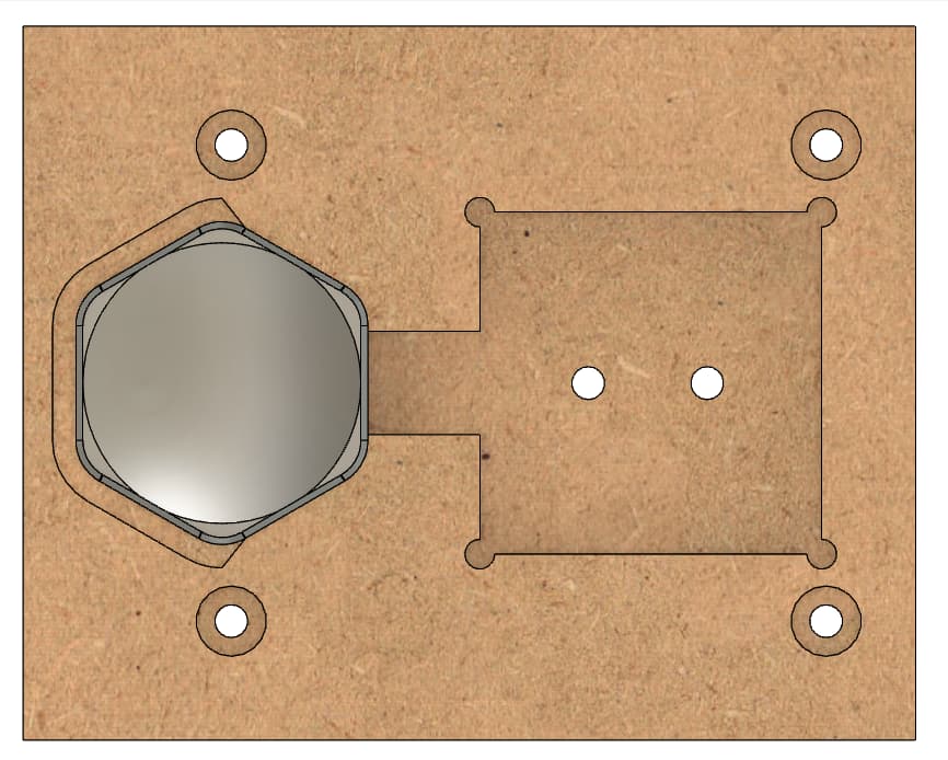
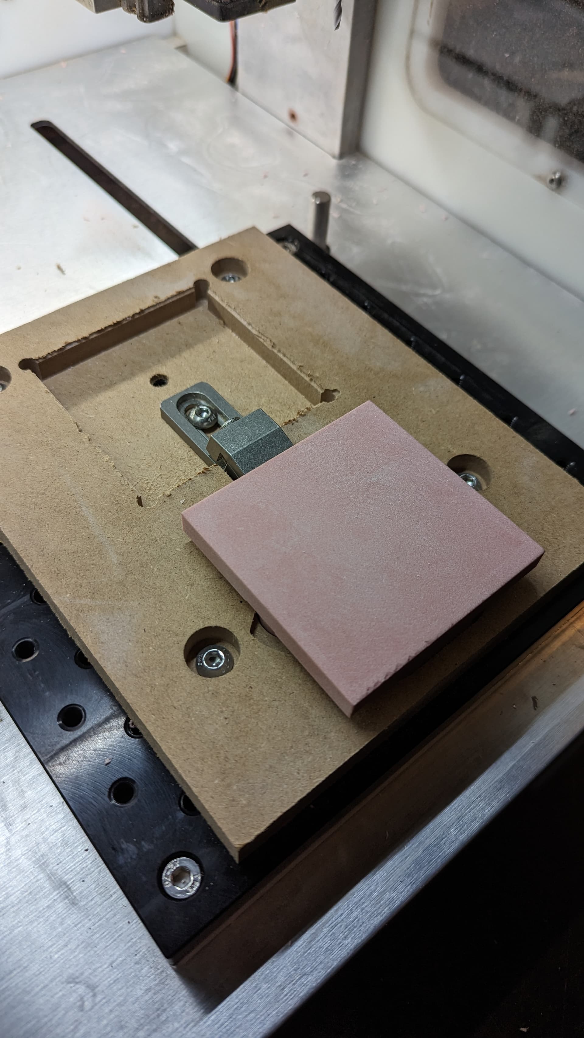
i designed this fixture intended to be made from MDF to hold the stock, and be mounted to the threaded table.
v1 of the coin will be made from renshape since i picked up a bunch of it when i ordered the nomad on black friday, and then i have a billet/block of aluminum (i believe it to be 6061, it machined really well on my old CNC when i tried my first foray into the world of desktop machines) that i want to make the final version from.
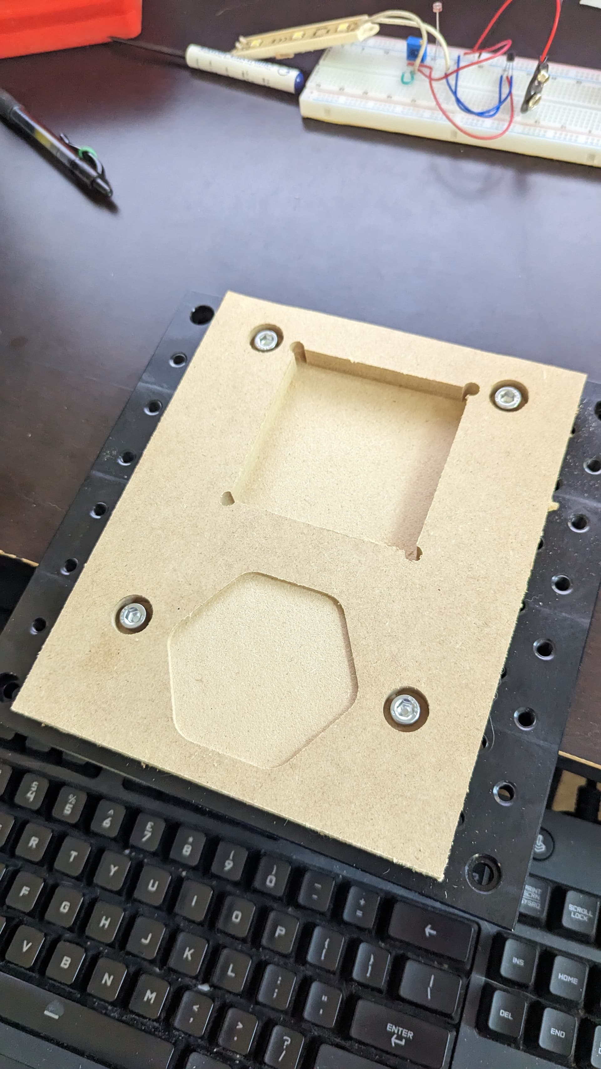
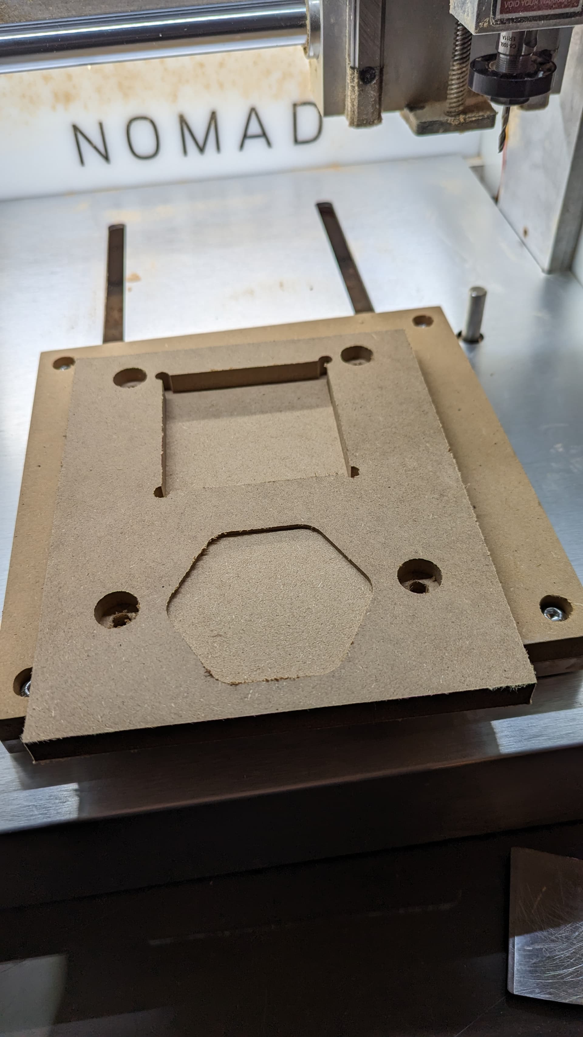
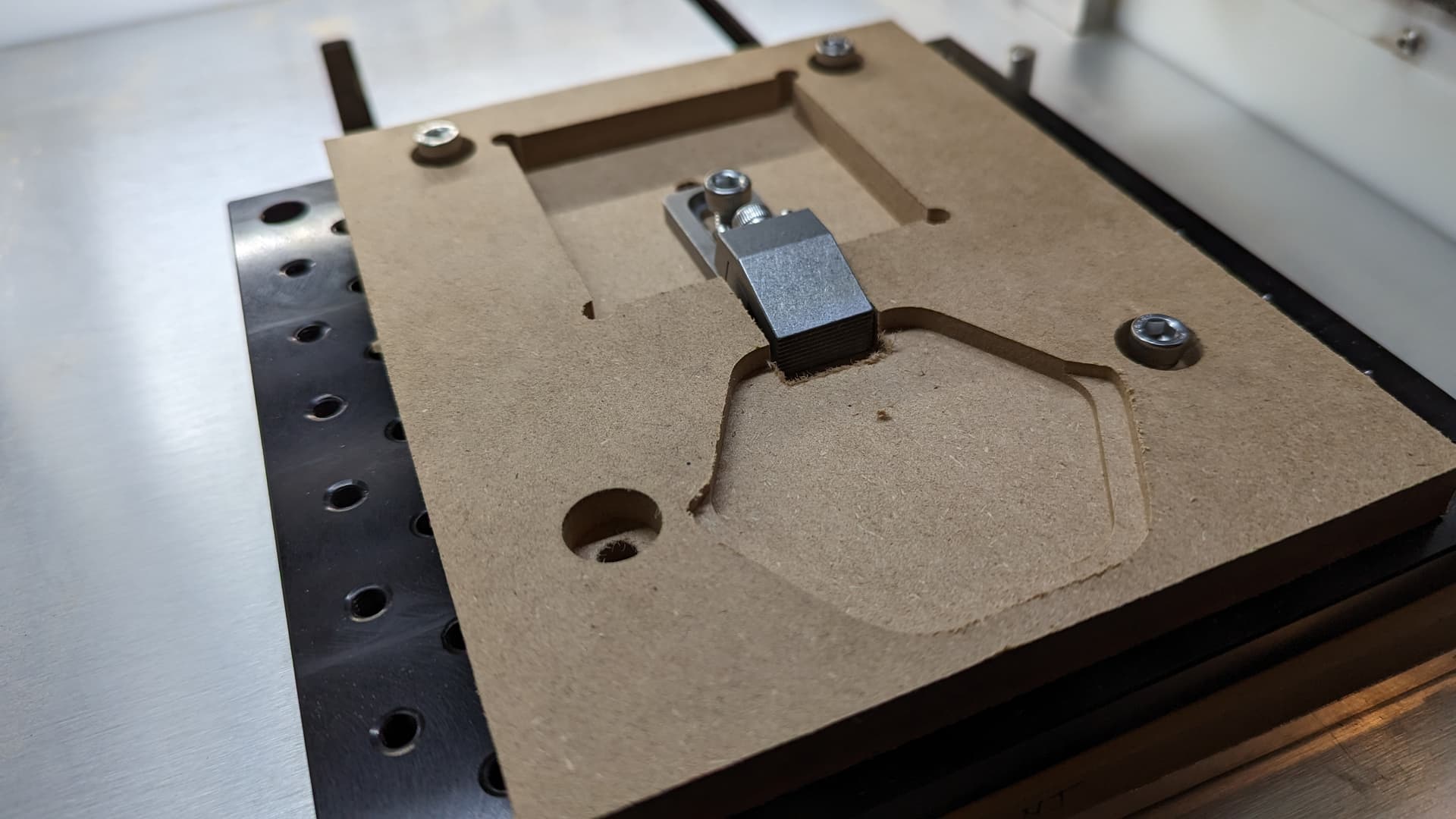
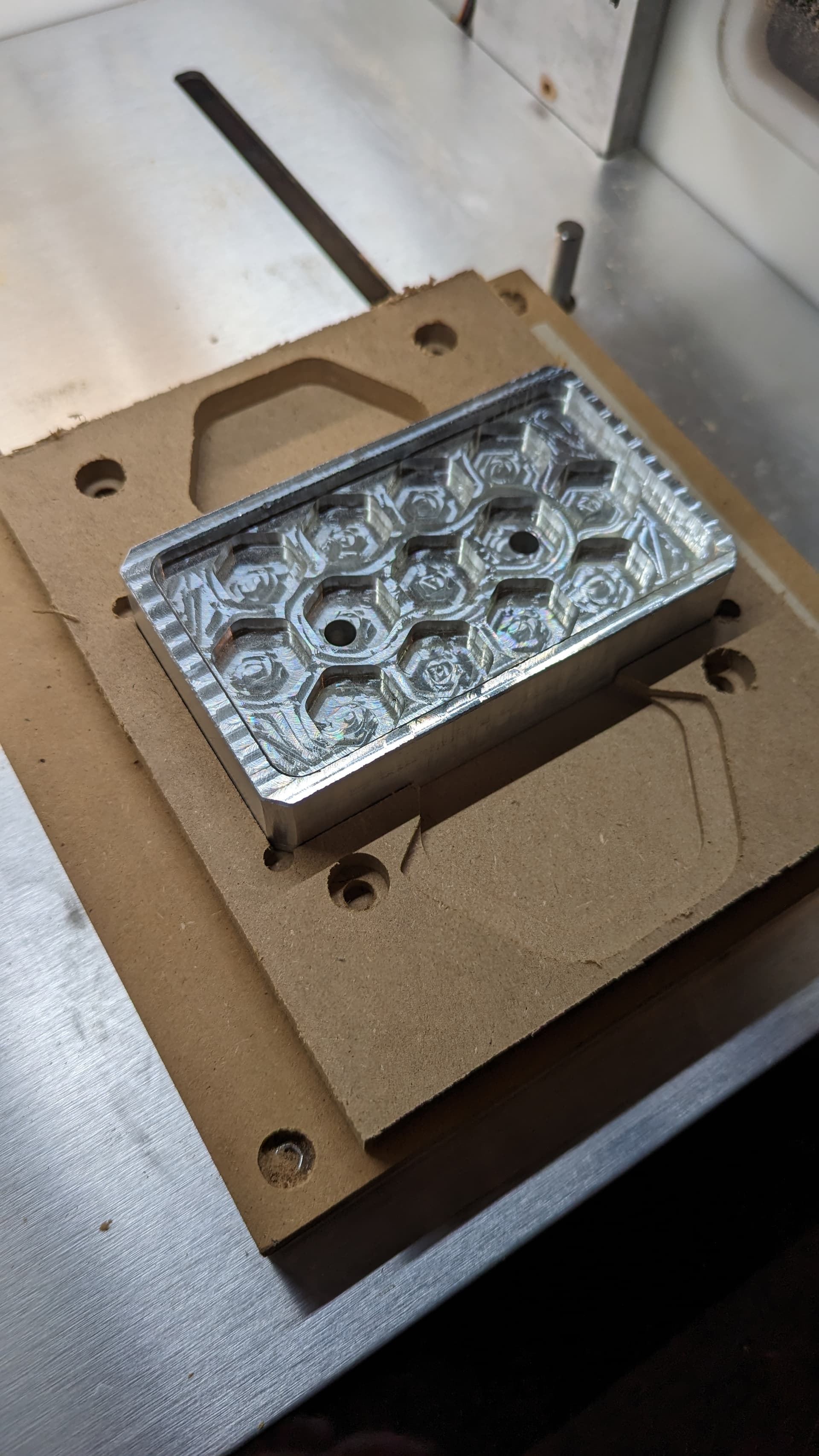
fresh off the nomad, and mounted to the threaded table as a test. seeing the 2nd side operation pocket i dont know how well that will actually do holding the stock in place.
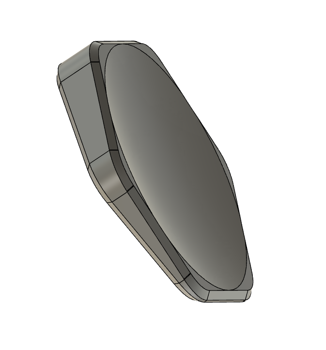
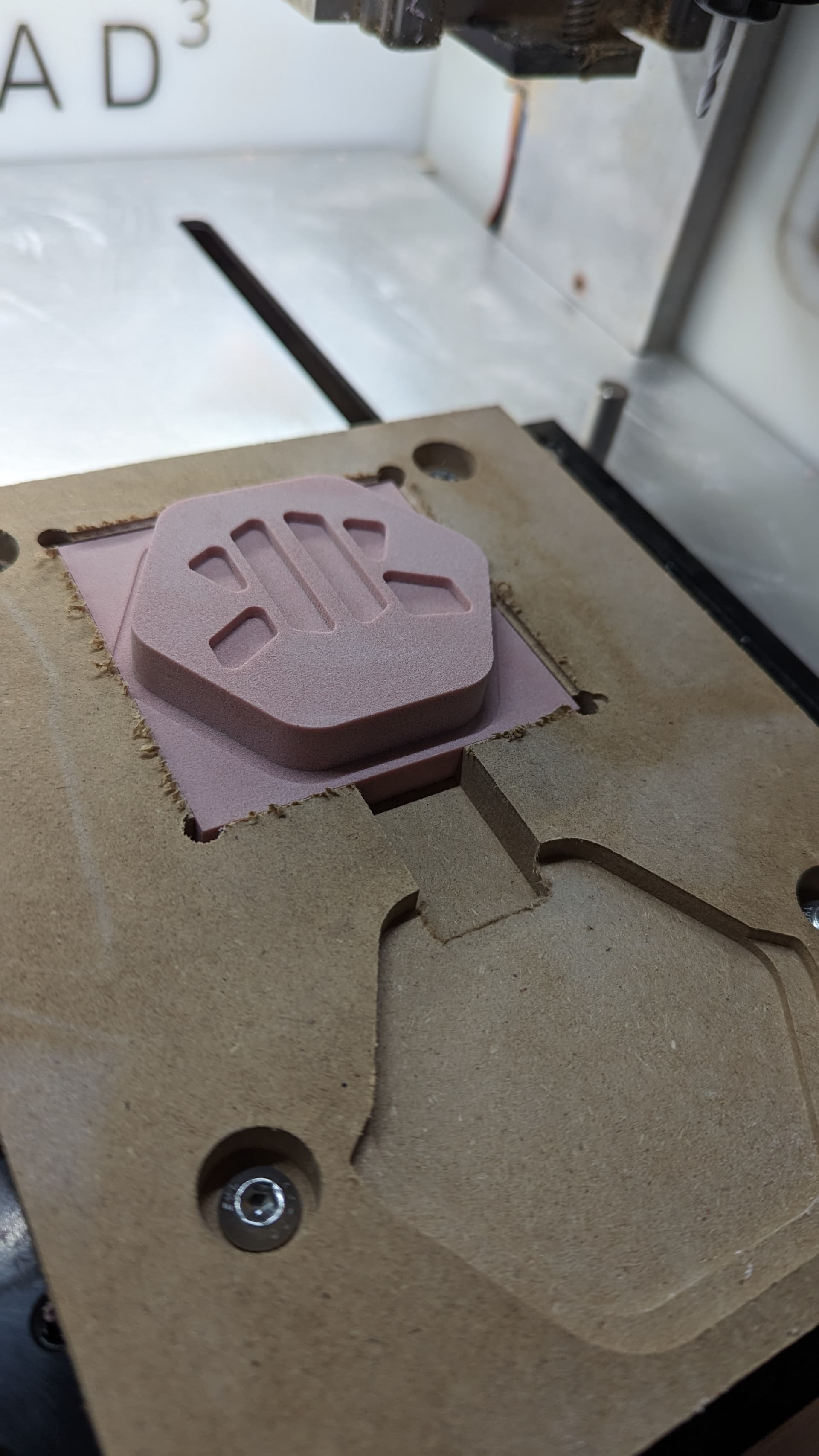
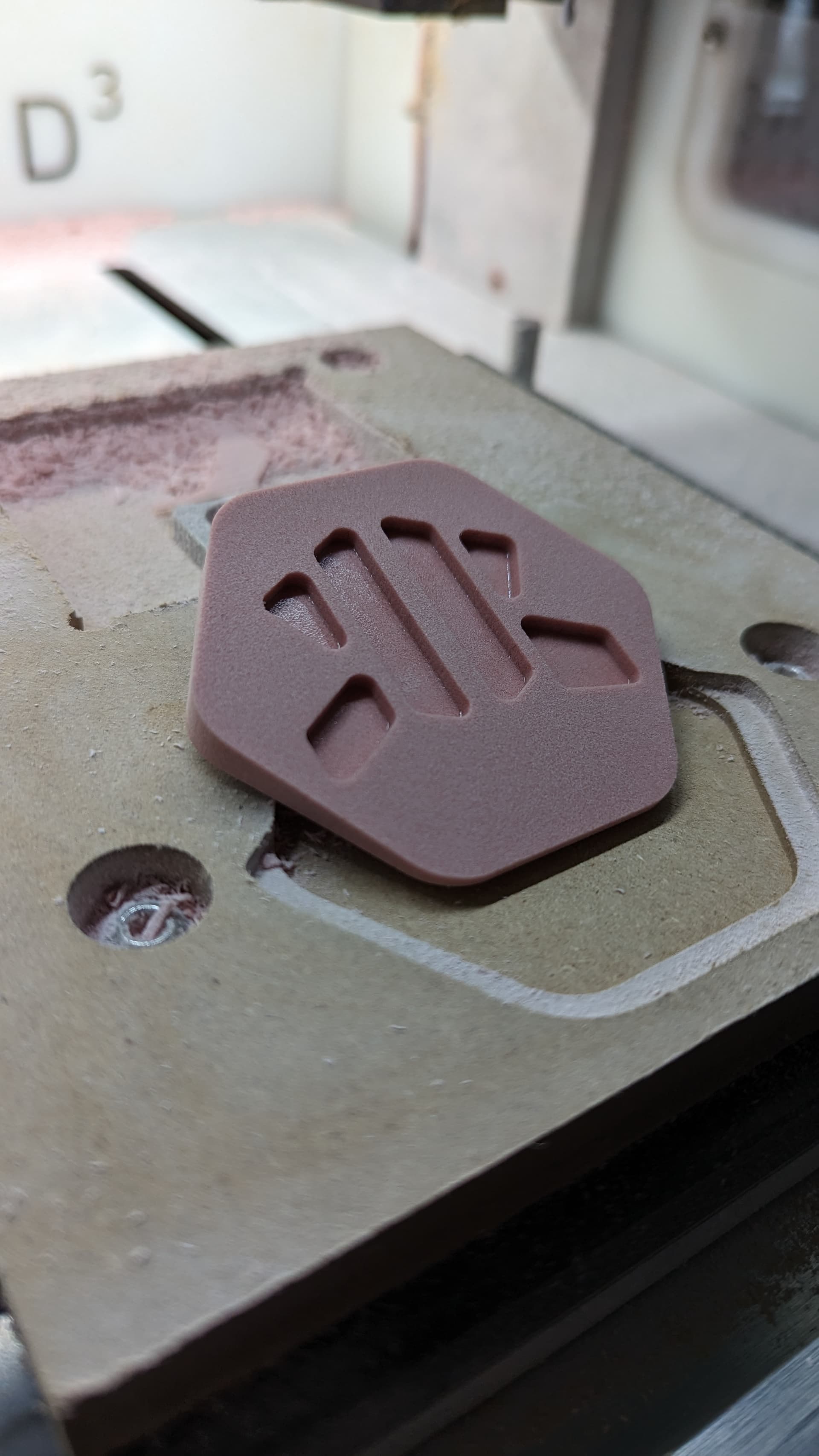
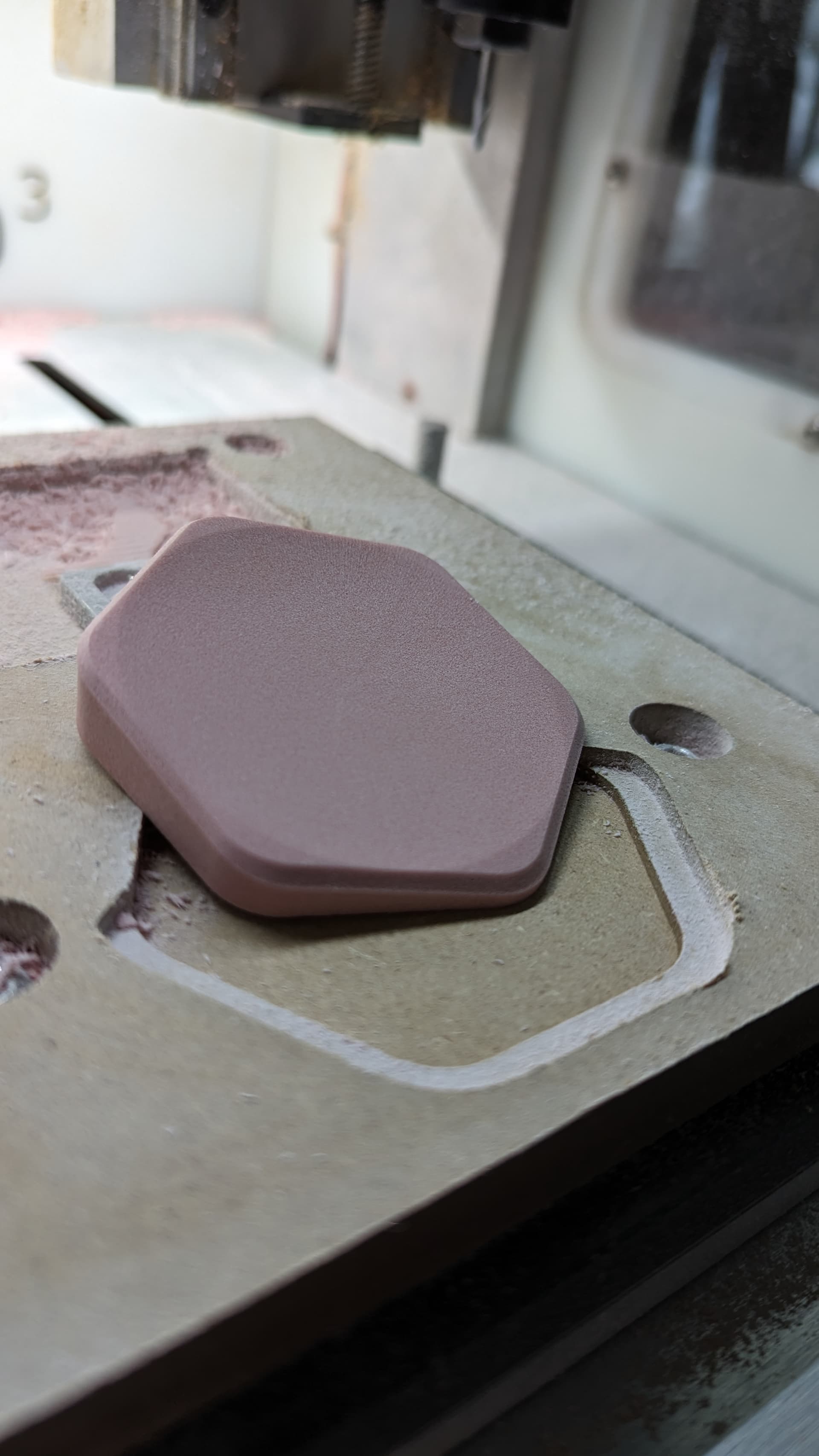
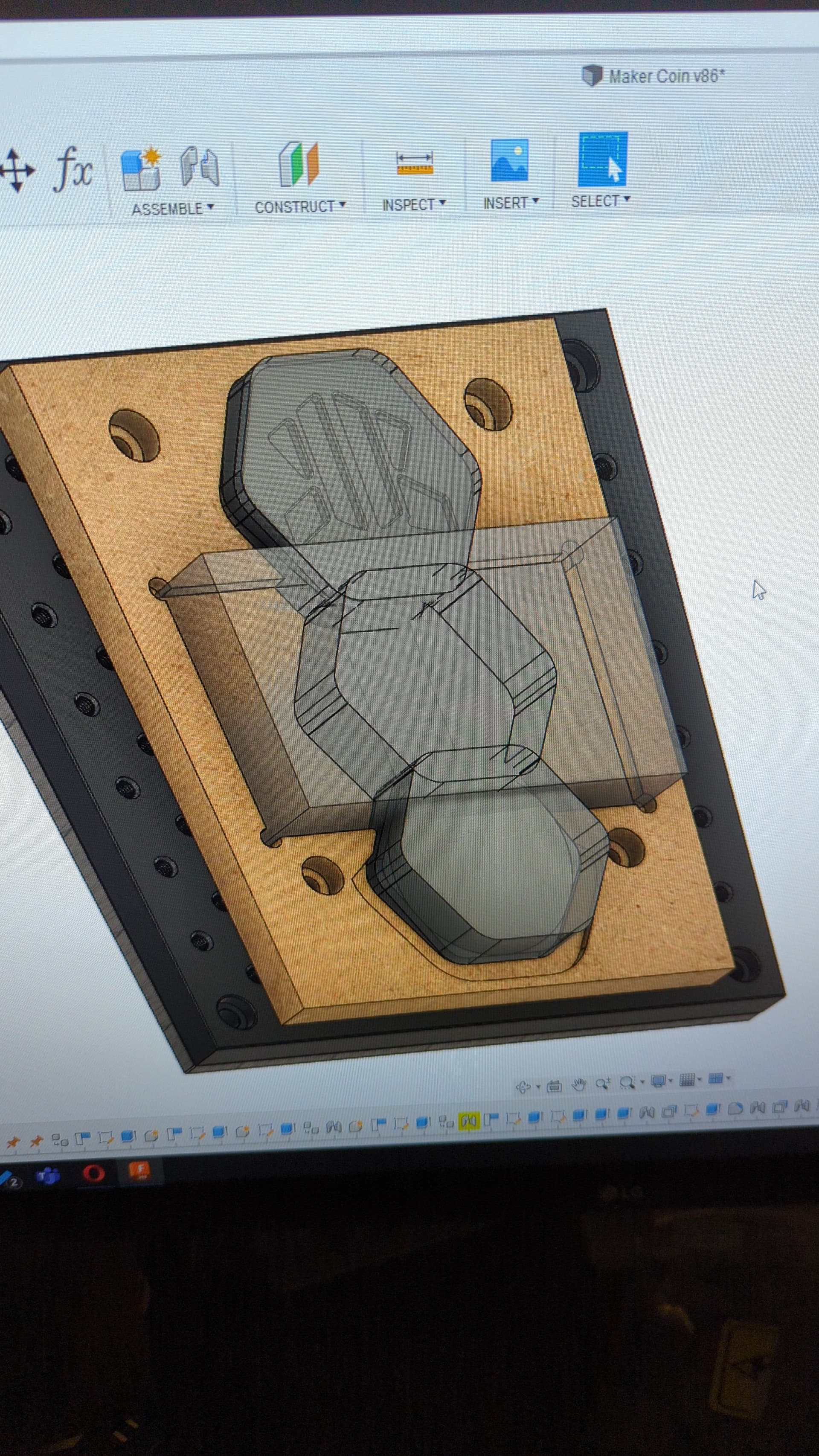
a few views of the maker coin for fun. went through few iterations to try and make it interesting. the angled backplate will make it a little more interesting as a desktop tchotchke / decoration, since it will sit the logo facing towards you, and the bowl cutout makes it less of this giant block of material.
yeah, im not sure how im going to go about that. theres not a whole lot of material to hold onto once it gets to that second sided op. i can adjust the program zero to the top of the stock, but if it comes loose or something happens i have no way to re-set the zero point, or account for the thickness of the double sided tape. i might have to think on that a bit more.
unless i was able to put the pocket at an angle, then the coin would be able to sit further into the pocket.
I would painters tape glue the stock to a flat base and adaptive the out side so you have a hexagon blank. Set Z zero to the bottom so you don’t cut past the tape.
Then contour to finished dimension surface it and do the flat side logo machining and chamfers. This will allow you to use the tape glue method again for the back side work in a shallow pocket. just make sure you add some relief to get a tool under the piece after to pry it up.
once i flip the stock over, and put it in the hexagon pocket, i would machine out the other side, this pocket is also intended to be press-fit, but i don’t think there is enough to hold that second side piece in place with that alone.
(although now that im looking at my setup, i set my zero to the stock top, so i can use double sided tape anyways without screwing anything up)
The point of cutting the hex out completely on op 1 is so you don’t end up with a top hat of material left to machine off on side 2. I find milling off a top hat adds a lot of extra stress to work holding and if you can avoid having to do so helps greatly especially if your work holding is not very strong.
Think about your jig and modify it something like this one I made to hold a round piece. I cut a slot on the table saw (or the CNC). This way you can either put a clamp on the jig or you could drill in a threaded insert and put a long bolt all the way through to hold it in place. I was going the threaded insert route but at the last minute just put a clamp on for this one time project. The holes were to secure it to my spoilboard with 1/4-20 bolts. My project was about 2" tall so I put spacers under the jig to lift it up enough so the round part was high enough to vcarve.
For the second op, if you use a thicker piece of MDF, you could probably make a pocket to mostly-recess a tiger claw clamp. Rotate your coin 90 degrees, so the thicker side points to the left or right where you have more room to integrate workholding.
i see. that makes sense. this is going to be a one off thing so, i might see if i can get away with double sided tape, but for my future 2 sided fixtures ill keep that in mind.
i do have more MDF (same thickness unfortunately), but i could design a second fixture and see if i can figure out a way to incorporate a clamp for the second side. i could also glue/screw 2 pieces of MDF together where i need the additional thickness.
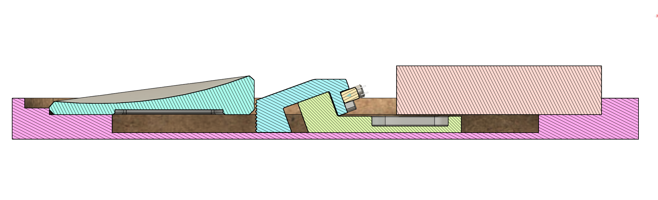
Laminating two sheets should work. Here’s a visual for what I was trying to describe. Except use a tiger claw instead of a static Gator clamp to apply lateral force. Also, you might want to pocket away some MDF on the thin side of the coin to give clearance for finishing endmills to work.
i see! very nicely done. (side note: that video was awesome)
ill have to think on how i can salvage this fixture and implement that clamping method. fortunately i have tiger claw clamps, and some metal dowel pins, so i could probably implement something that will work.
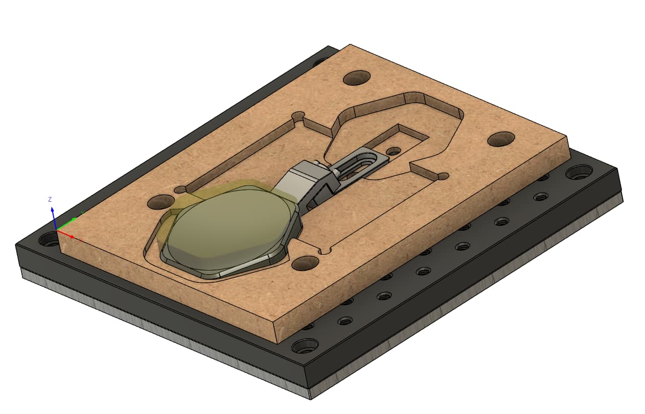
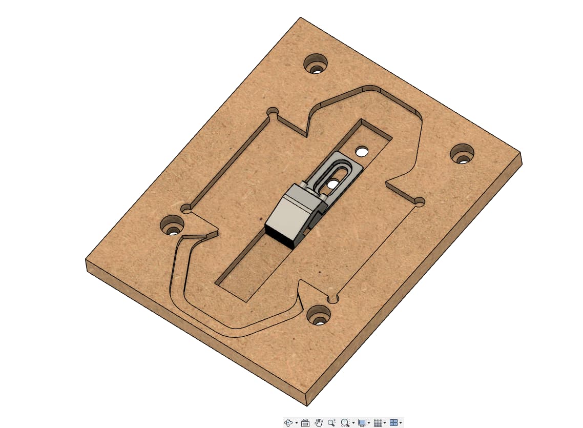
i think this might work, this drops the pocket down further, and lets the tiger clamp live within OP1 pocket, and secure itself to the threaded plate below, and cuts out a recess around the lower areas.
i would love to be able to add a tiger claw model into there to made sure fusion knows to avoid it. (a few of my toolpaths will probably hit it i think.
everything is pretty spot on, for re-zeroing and aligning it with a “machinist” square from amazon.
for some reason my bores didnt go all they way through, but i just took care of that with a drill bit manually, the depth/tolerance for that doesnt really matter, just needs to let the clamp…clamp. hopefully theres enough meat in the thinner pocket so the coin doesnt push out, but i dont think clamping against the small side would work since i need to machine around the thin area, and endmill + clamp = sad.
i made an oops and trusted that my renshape stock would be as i described, aaaand also forgot to adjust the stickout for the thickness of the material.
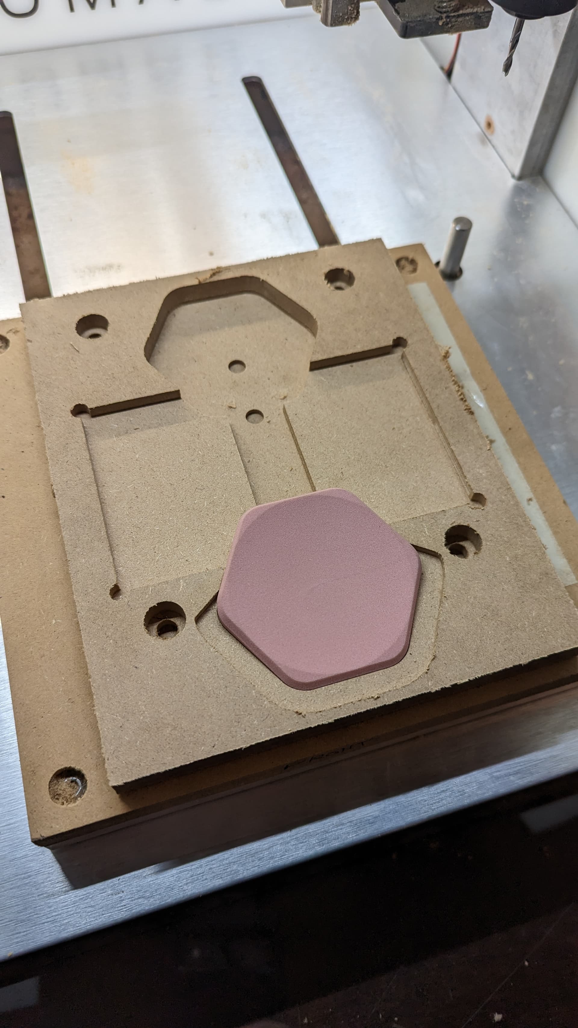
(the renshape pieces i got with my nomad shouldve measured 76.2mm, they actually measured at 73mm), so my cutout ended up not being perfect, but i was able to use the fixture as my zero (wcs was using a square piece of stock as zero originally) and i had plenty of wiggle room, since my model is much smaller than my stock, even after cutting it to fit into the pocket.
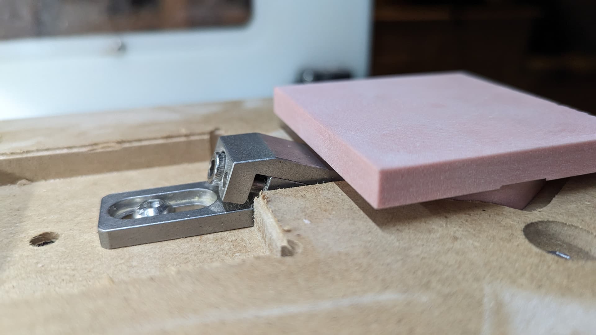
it also fits into the op2 pocket, but its a bit loose since i removed the fixture and then put it back to make the fix and just used the amazon-machinist square to “tram” it in. note the use of quotes, i know thats not the right way to do it.
but im not going for crazy tolerances with this project. just trying to understand the basics of 2 sided machining which i will definitely need going forward.
also…the toolpath did a bit of self clearancing into my fixture which apparently even though i selected it in the setup fusion decided it was cool to just cut right through it. but i might have done something wrong.
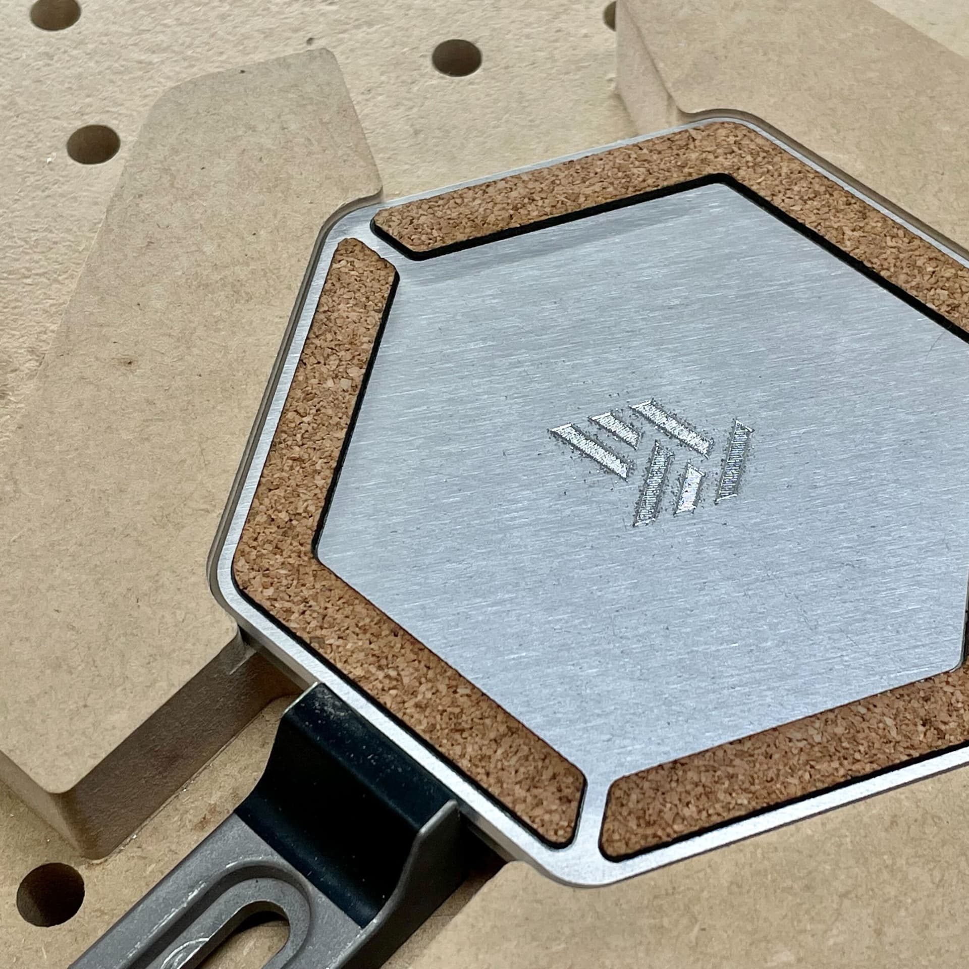
great success. I didnt have a chamfering tool, and didnt think to just make a toolpath with a ball endmill to do the top chamfer when i ran op1 last night.
but i thought about it afterwards for op2, so i was able to do my first mid-op tool change which went swimmingly.
overall, for not really being super precise, this came out AMAZING.
now to re-make the fixture (and maybe improve it a bit) for the aluminum version.
if you want to watch the machining, see the post below.
probably a duh moment for everyone else here, but apparently .05mm is still too much clearance for a press fit, either that or the MDF is tearing out a bit. anyone have any thoughts?
debating making another v2 fixture.
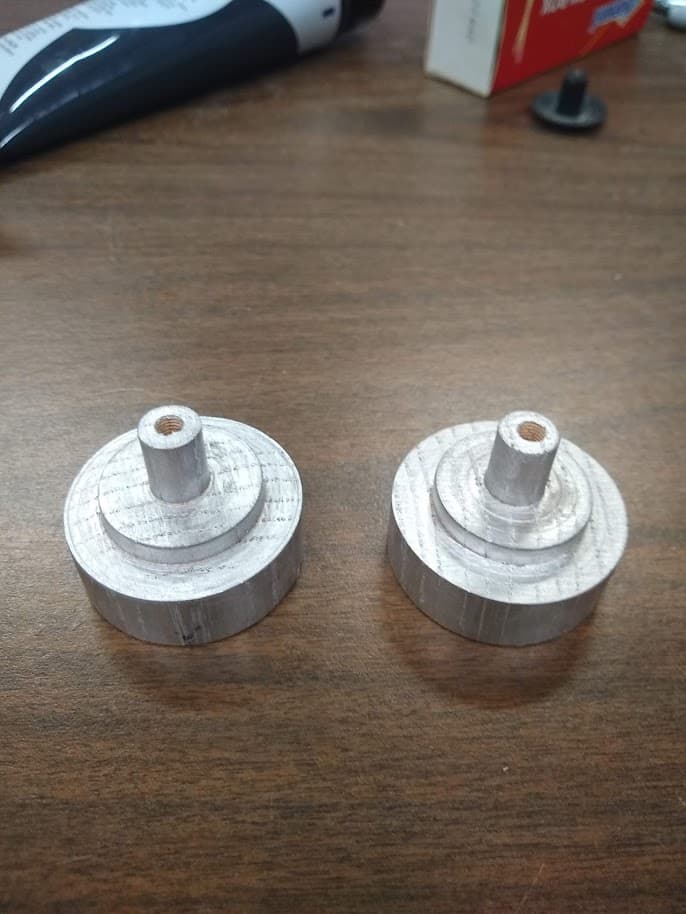
the aluminum pocket i cut out to the exact real life dimensions and im able to press fit it in, and getting it out required a decent amount of prying.
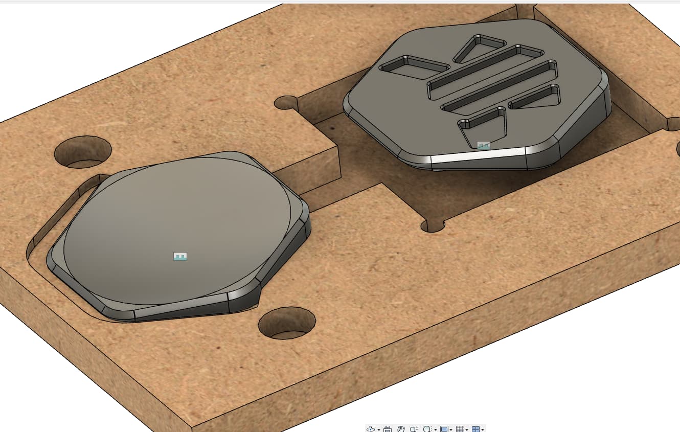
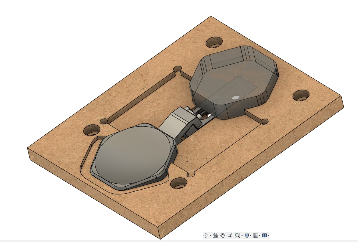
the v2 fixture in fusion with the expected puck of aluminum ill be left with after milling that big billet of aluminum
I forgot that support sent me a tiger claw model when i asked for the Nomad Threaded Table Model to use as a fixture reference, so i was able to add one in and select it as part of the fixture which is cool. Now i can actually see in the simulation that my toolpaths will miss it rather than trusting my math alone.
aaaand i adjusted my fixture…again. because i was thinking that if i decide to make some other type of coin and do a production run (my thought process is i really like how this coin fits in the hand, and it could be a fidget object of some kind) that if i was able to batch process a bunch of stock, and be able to leave the clamp in place when running the actual operations on the coins that would be more efficient, and machining the fixture itself would take less time to have it change between the multiple pocket depths.
shown here, the first op stock can sit above the tiger claw clamp and leave it in place, and wont come close to it during machining
and shown here, the main pocket is now all one level, rather than being 3 separate levels, and should provide plenty of support for both the first and second operation.
i also discovered the scrap piece of aluminum i have wont work for making the coin out of aluminum, so i found some cheap 6061 stock on eBay and bought it so i can bring this project to fruition, and move on to projects that hopefully have promise of making me money.
I’ve been meaning to just model up the tigerclaws so I can do just that with some of my jigs, I never thought to ask C3D if they would share a model. Any chance you could share that model to reference?