Making a base for a model

which when imported and aligned gives us:

So we draw in a vertical line, align it with first and penultimate circle:

and we make that many more

and space them evenly between the first two:

and align them neatly:

which can then be aligned with the project:

and slightly increased in height:

Done

We then draw in a rectangle to measure the depth of each circle:

and assign the matching line a toolpath to that depth:

and repeat until we arrive at:

We then need to repeat this for the sides and the rounded form at the ends.

Again, we draw in a rectangle of the correct width and position circles to indicate the perimeter cuts along the base and add a circle at the top to stand in for the rounding at the top:

Then we draw in a line:

and zoom in and Node Edit to make it tangent to two of the circles:

Note that this pretty much requires zooming in/out and switching back and forth betwixt each end to make things line up as they ought:

Done

Since duplicating geometry will keep Toolpaths associated we only need to do one side for the nonce.

Again, we draw in a pair of circles:

and get a blend…

1 Like

However, we have a brief digression — the rounded form of the top of the stand, since it is essentially part of a cylinder rotated in space describes a parabola, so we model a cylinder rotated thus in 3D:

and then slice it to get the geometry for the parabola:

which we export to SVG so that we can make use of it.

1 Like

With the parabola geometry, and the other geometry, we create a blend which should work for the balance of the stand part:

(but will probably require some work with a file or rasp — my theory on how the original was made is that it involved a router table and a number of fixtures — anyone else have any good theories?)

1 Like

Again, we draw a rectangle:

and use it to set the depth for a toolpath:

Repeat until one arrives at…

1 Like

A post was split to a new topic: P51 for a 2x4 contest

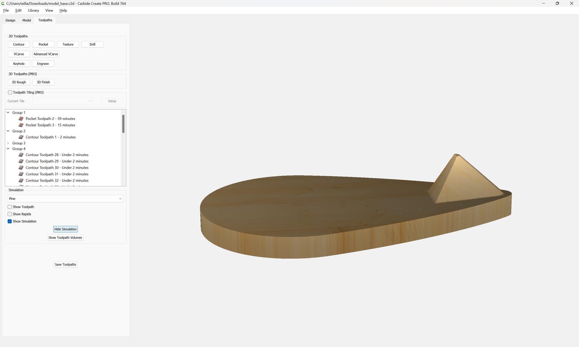
Apparently the math wasn’t quite right for the apex.

Adjusting that is left as an exercise for the reader.

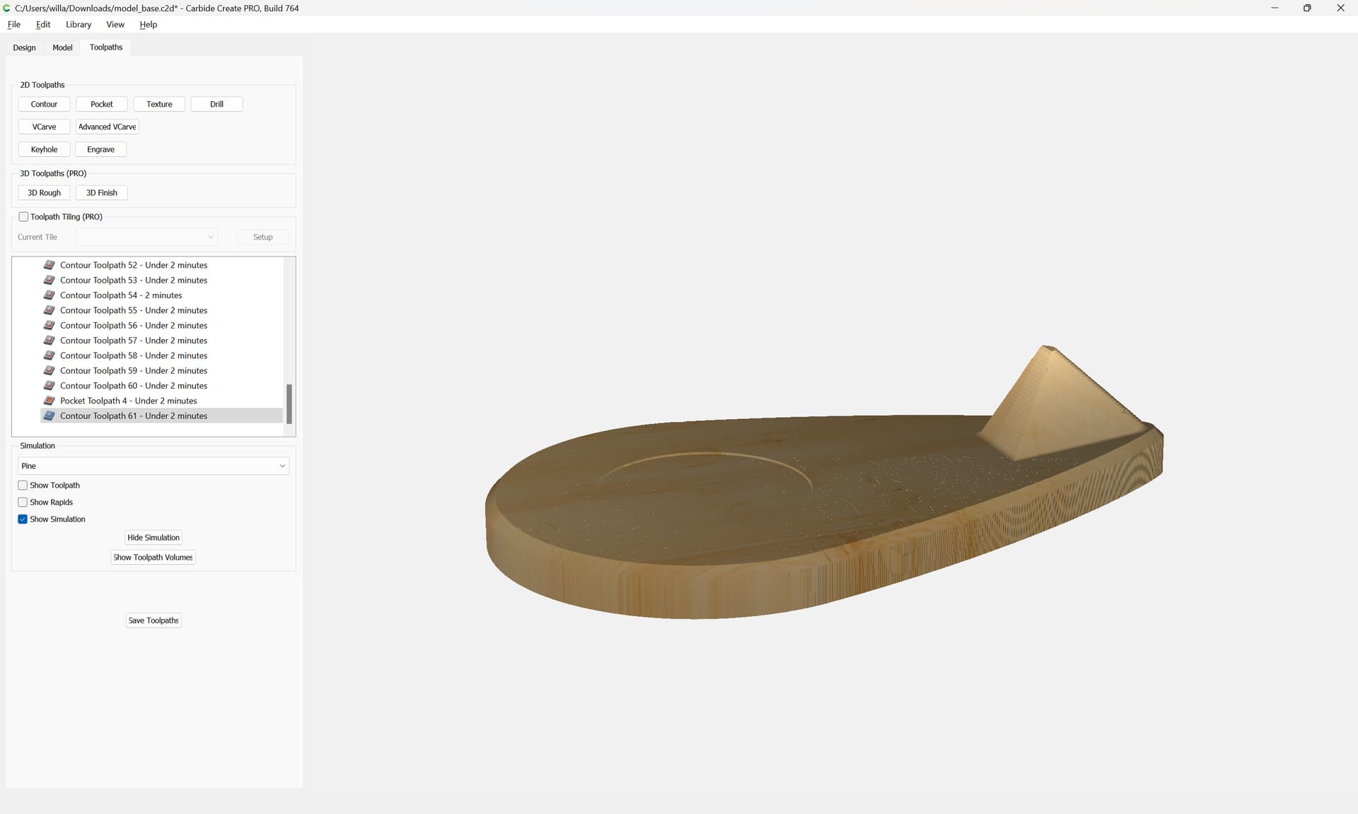
To get a chamfer around the base see:

A V endmill is a good approximation for now.

and of course, one will want a slight inset for the nameplate:

as requested on support…

2 Likes

Lastly, speaking of jigs and fixtures, it will be necessary to create a jig to drill the hole for the model to be attached, this too is left as an exercise for the reader — let us know on support if assistance is needed with that.

Alternately, one might want to draw this entirely using the Curve tool…

It will help to minimize the stock area to just a bit more than what one is drawing, so drag the background around and adjust as needed to arrive at:

model_base_v7_background.c2d (232 KB)

Then one can use either the Curve tool, or the Polyline tool to draw in a rough half of the outline:

Done

model_base_v7_polyline.c2d (236 KB)

(note that I am uploading the file at each stage for inspection for folks who wish to follow along)

Go into Node Edit mode:

drag-select all the nodes:

right-click, or press S to change them to smooth nodes and instantiate the off-curve nodes:

Note that the top node was already smooth (indicated by being a circle, so select it and change it again)

model_base_v7_smoothednodes.c2d (236 KB)

Zoom in on a pair of nodes:

and adjust them for position if need be:

begin dragging the off-curve nodes to adjust the shape:

If need be, fine-tune the on-curve node position(s):

and then continue adjusting the on-curve nodes until one arrives at:

(resist the urge to add an additional node along a curve unless necessary)

zoom out:

and begin adjusting the next section:

which seems good when zoomed in a bit:

so we move on to the last segment:

where we discover that two nodes were placed in the initial drawing

select the errant node and delete it by right-clicking and choosing Delete Node or pressing d

Reposition the node which was moved:

and while holding alt (option on a Mac) drag the way out-of position off-curve node so that it reshapes the upper portion of the curve, but doesn’t move the associated off-curve node for the lower portion which is already in position:

adjust the remaining off-curve node:

and adjust the position of the on-curve node so that it is at the apex:

and adjust the off-curve node so that it is level so that when joined, the curve will be smooth, not pointed:

Done

model_base_v7_half.c2d (236 KB)

copy-paste the left half:

Mirror it horizontally:

and drag it into registration with the other half:

where we see that things don’t quite line up.

(I believe because the scan was a bit askew)

If we draw in a rectangle using the control key (command on a Mac) to get the offset we can get the dimensions of a triangle which we can use a bit of geometry/trigonometry:

to determine how much to rotate each half to bring them into alignment:

repeat for the other side with the negative/positive of the angle:

(delete the rectangle)

The two halves should now fit together:

select both:

Join Vectors

Yes

If desired, go into Node Edit mode and smooth out the top node.

model_base_v7_outline.c2d (236 KB)

I’m making progress! Now am up to when the toolpath uses the 1/8" ball-nosed tool to cut out the standing part of the base, when I to to pocket toolpath, it selects all, including the raised part? Thank you,

Another solid tutorial. Learning a lot! Thanks Will

Just had a thought - would it be more efficient to make the base as two separate pieces, the flat base and the upright separately and glue to the base vs cutting all as one piece?

Of course it would. But I have a CNC that can do it.

I have gotten to the point of doing something because I think I can, spending hours trying and learning from my mistakes.

Yes, that would be more efficient/easier, esp. in terms of material, but as @Spyd noted:

and doing this as a single, solid piece of wood has style points — plus as @Zman noted:

although that sort of brings us full circle — I’ve been contemplating how this would have been done by hand, and my answer keeps circling back to:

  • roughing out on a bandsaw
  • cleaning up using (many different) templates on a router table
  • drilling the recess hole with a large Forstner bit
  • a fixture on a drill press to drill the hole.

Post a screen grab or the current state of the file?

Likely issues:

  • don’t have the interior geometry selected
  • the interior geometry was made using Trim Vectors and hasn’t been joined so as to be closed yet
1 Like

I got it figured out, this has been a terrific learning tutorial - Zman you make an excellent point! Thanks for the assistance; I have had this for 2 weeks and the support has been phenomenal. Thanks Will!

This topic was automatically closed 30 days after the last reply. New replies are no longer allowed.