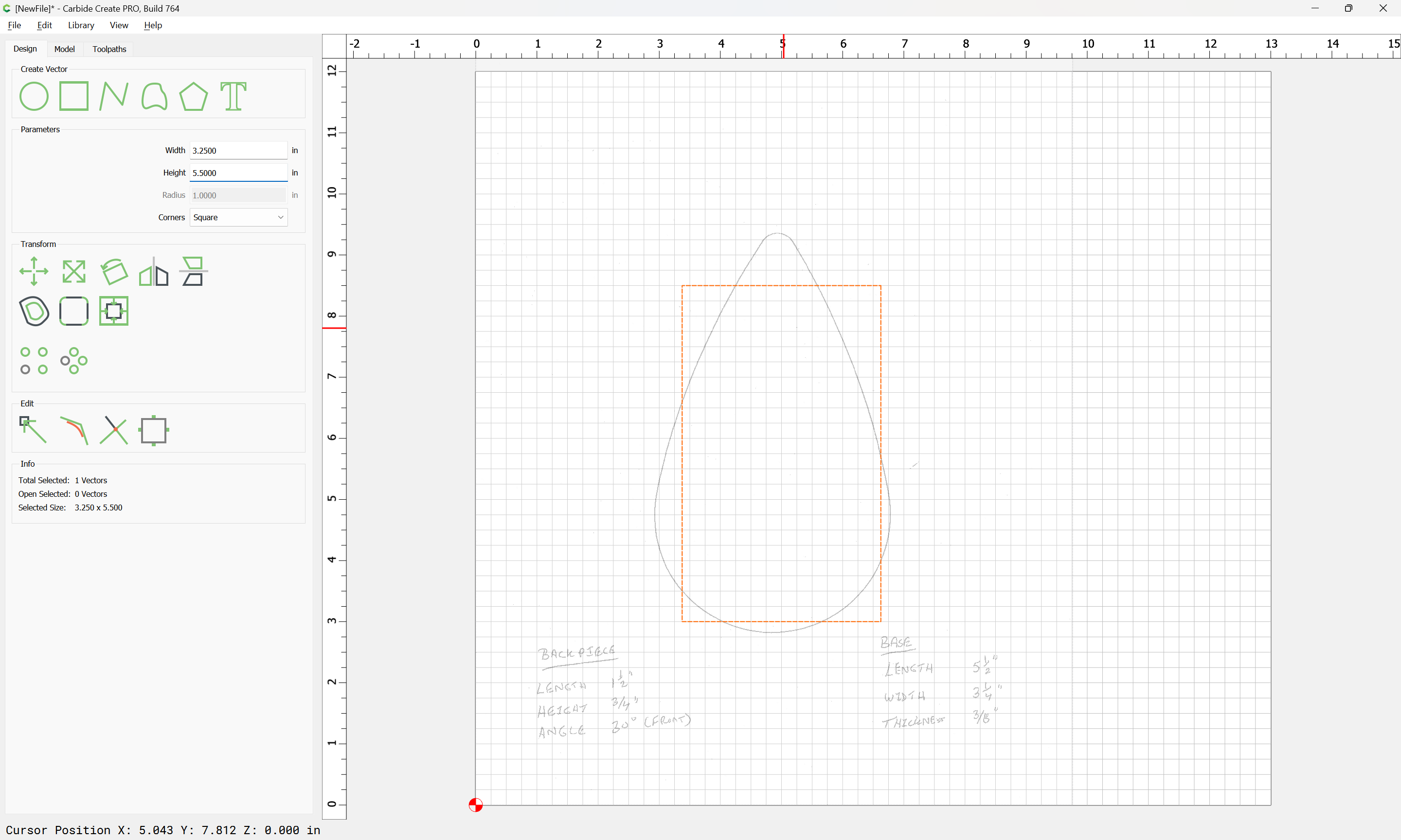
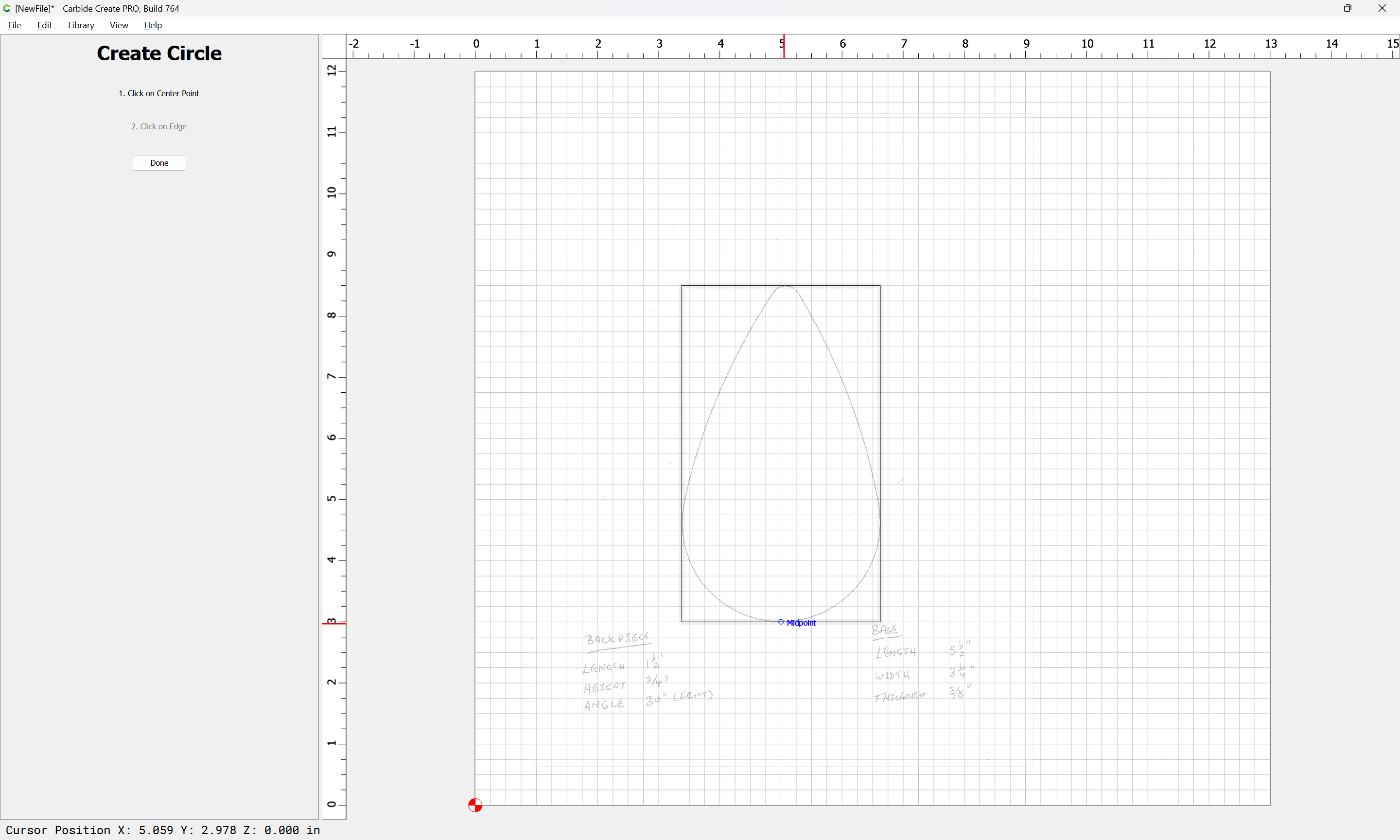
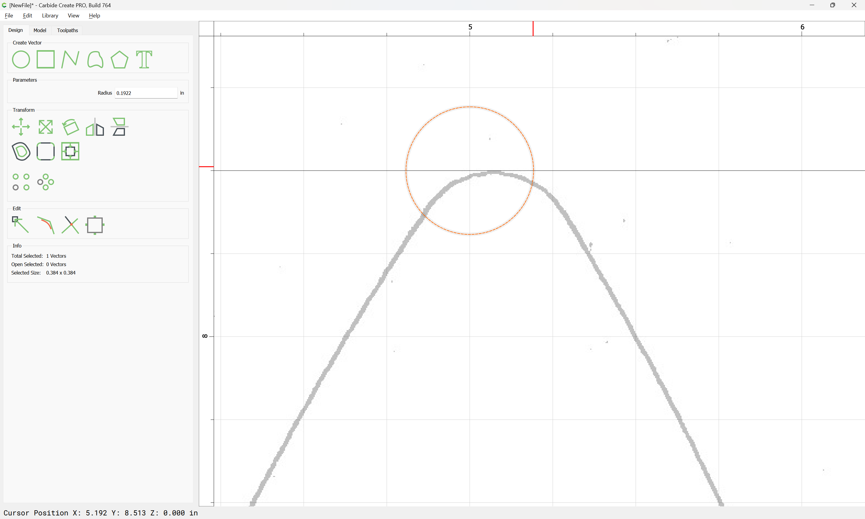
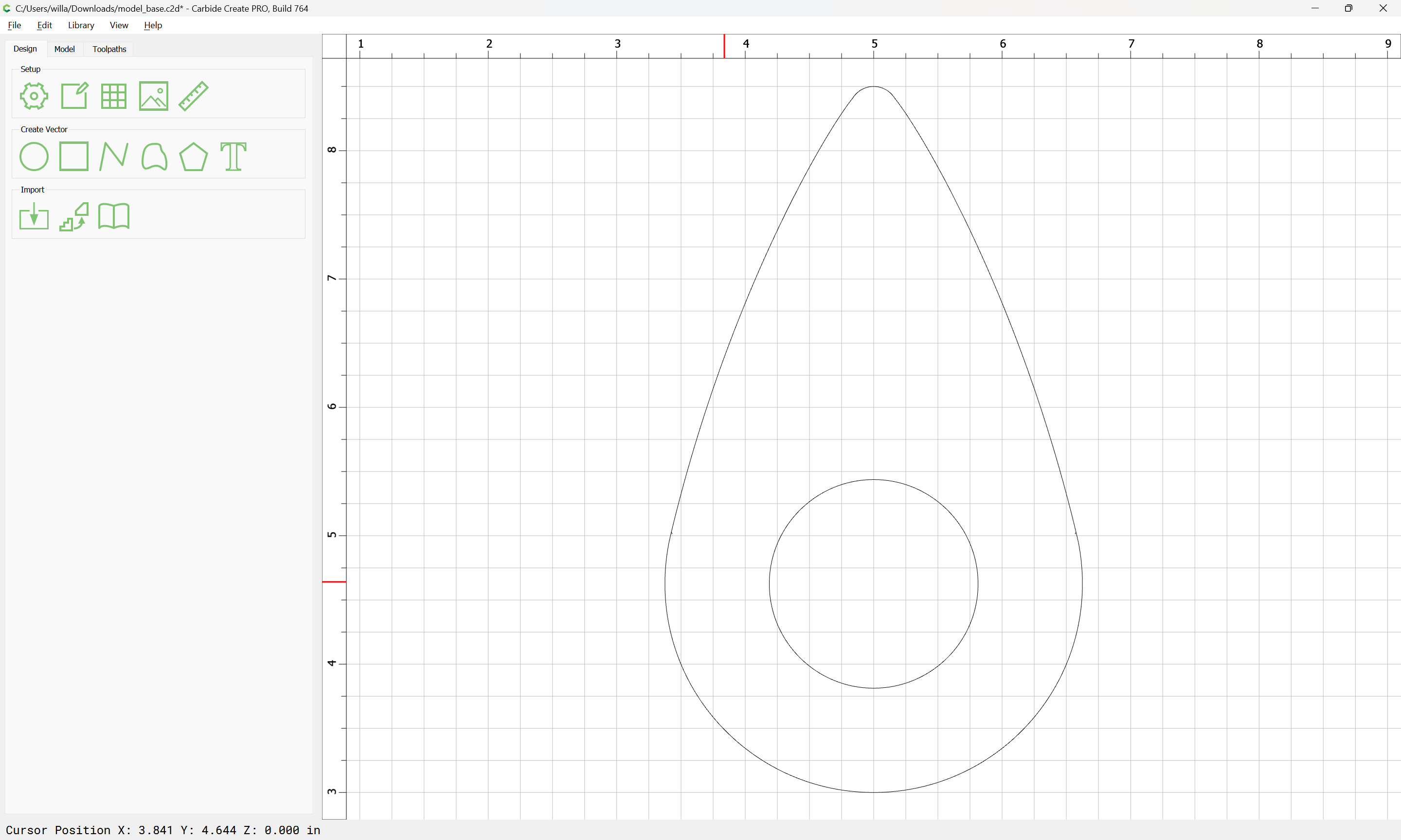
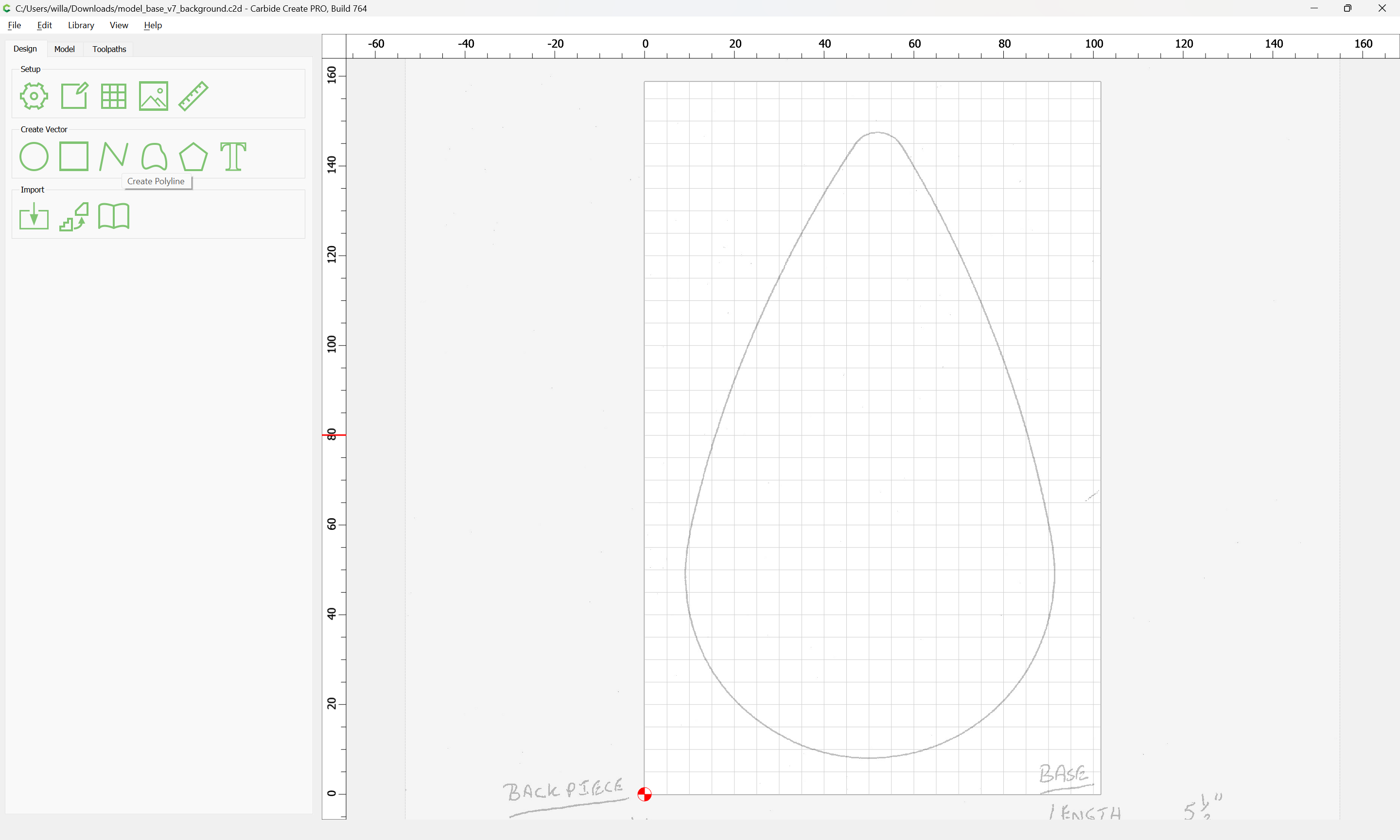
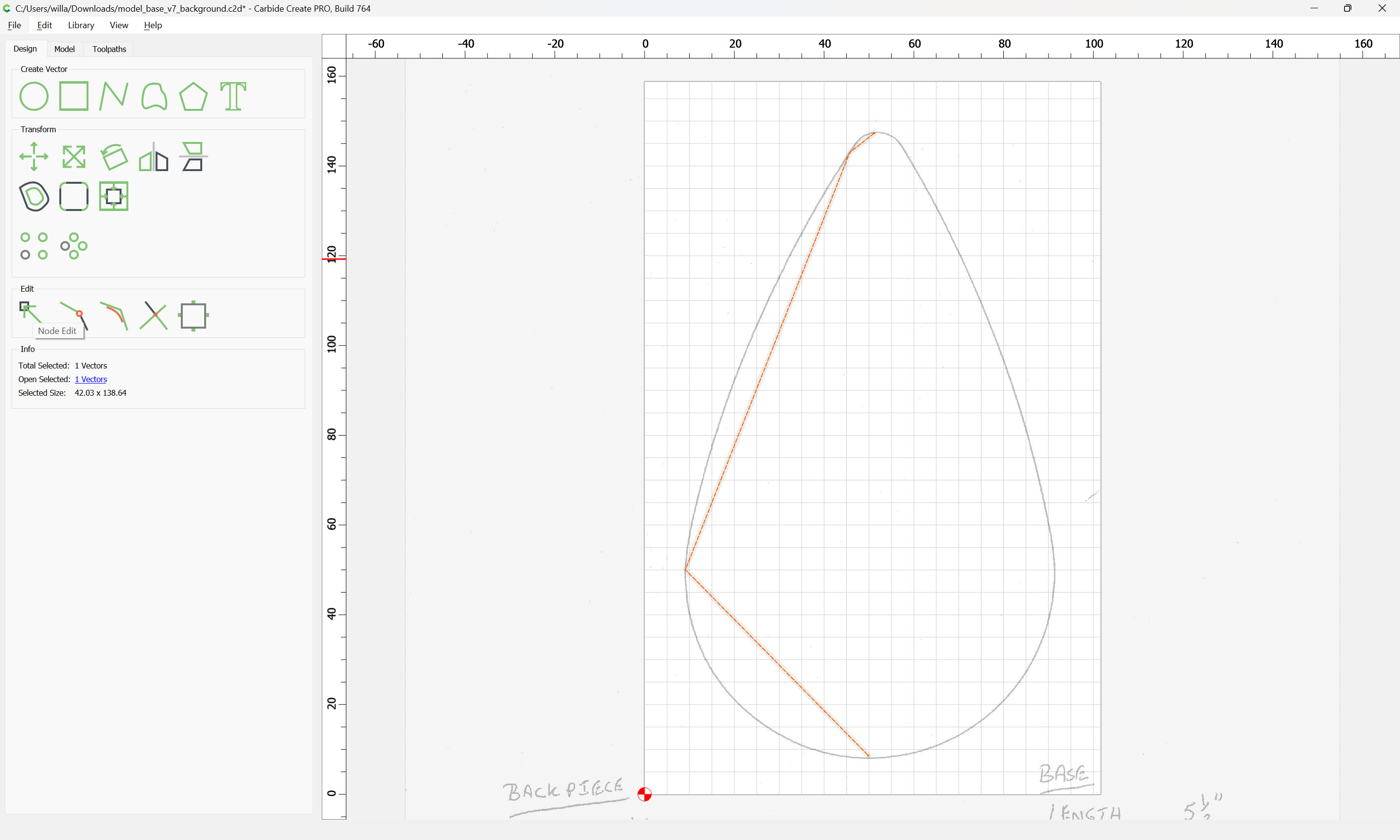
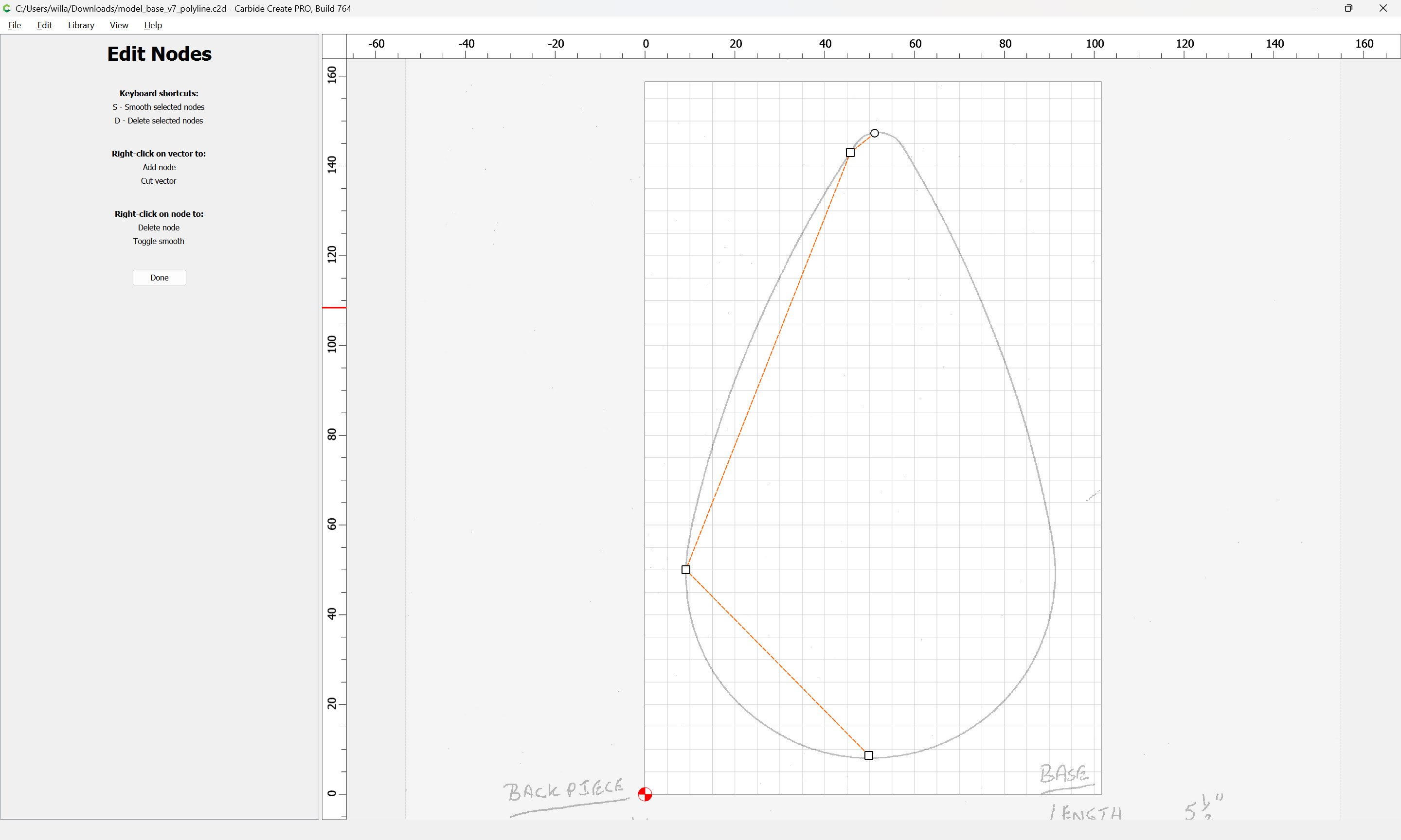
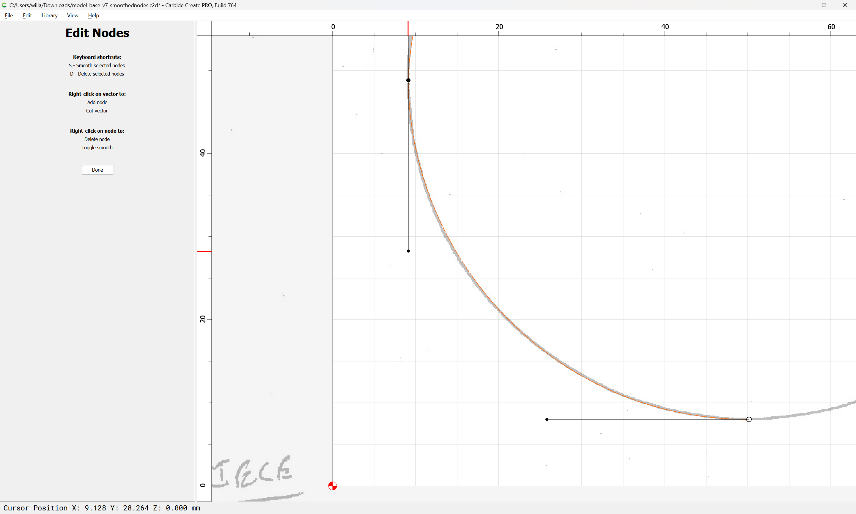
Zoom in on a pair of nodes:
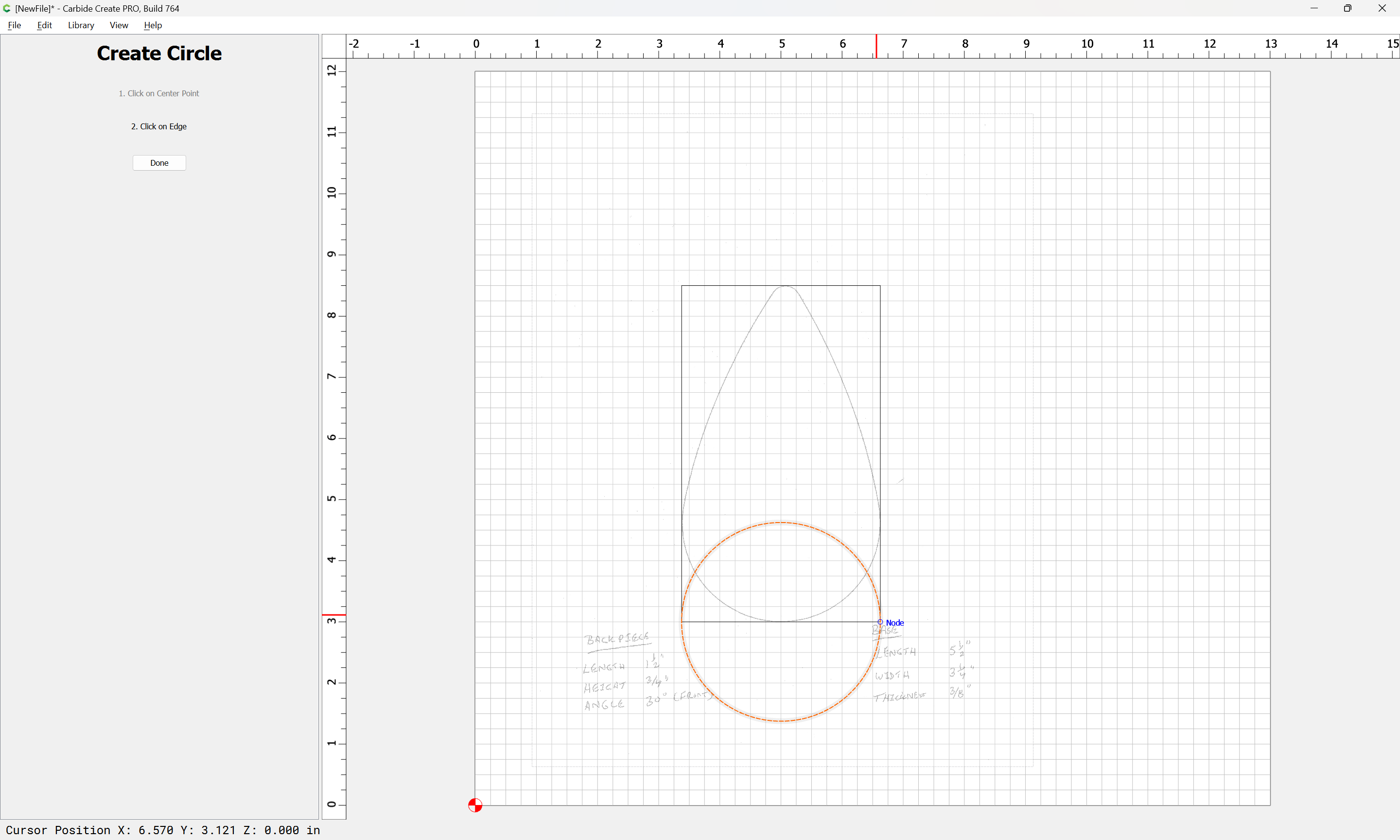
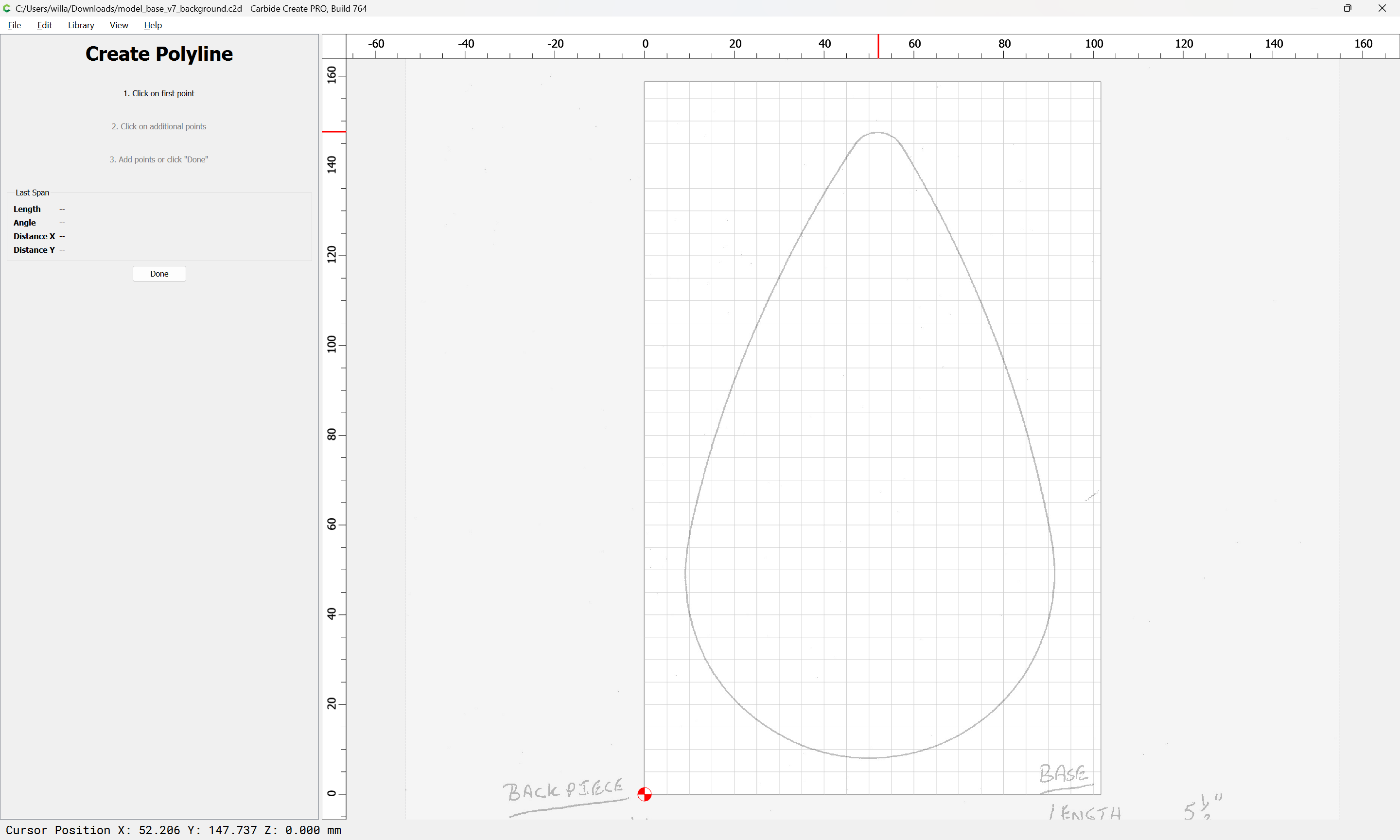
and adjust them for position if need be:
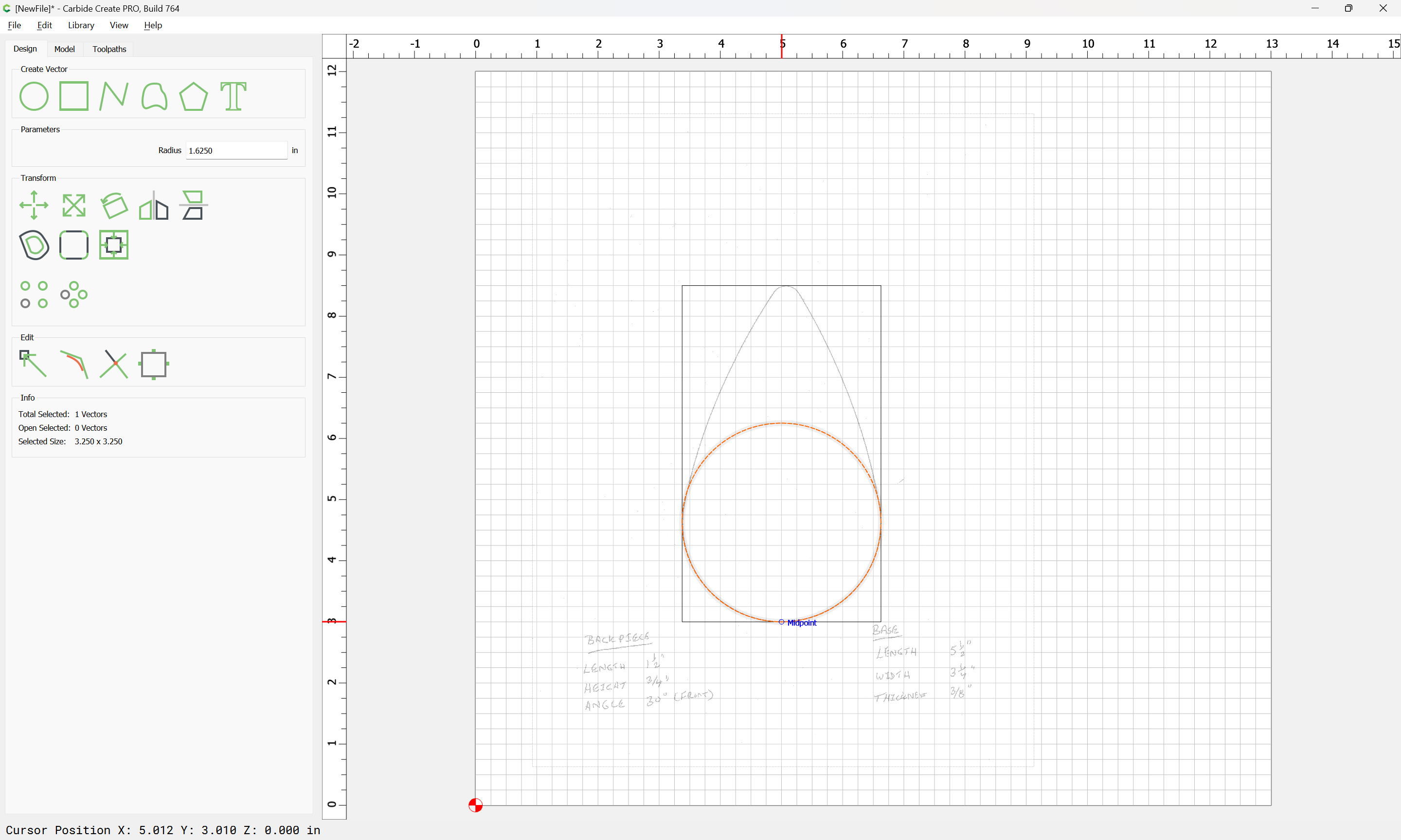
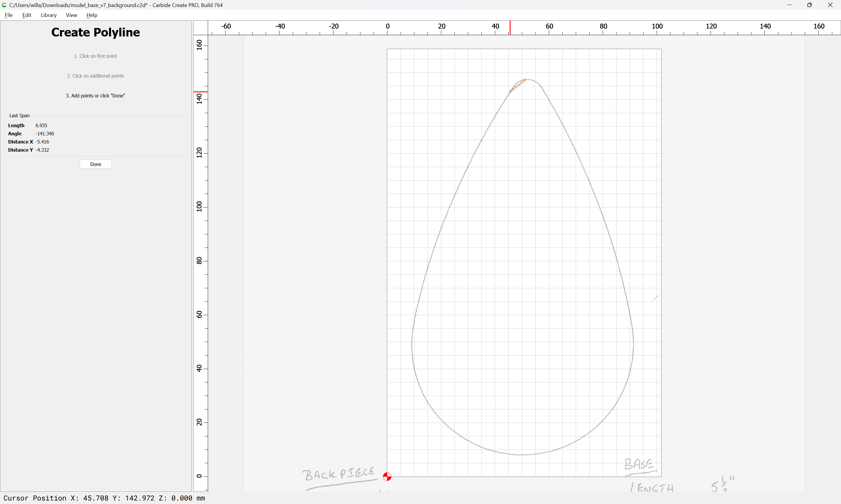
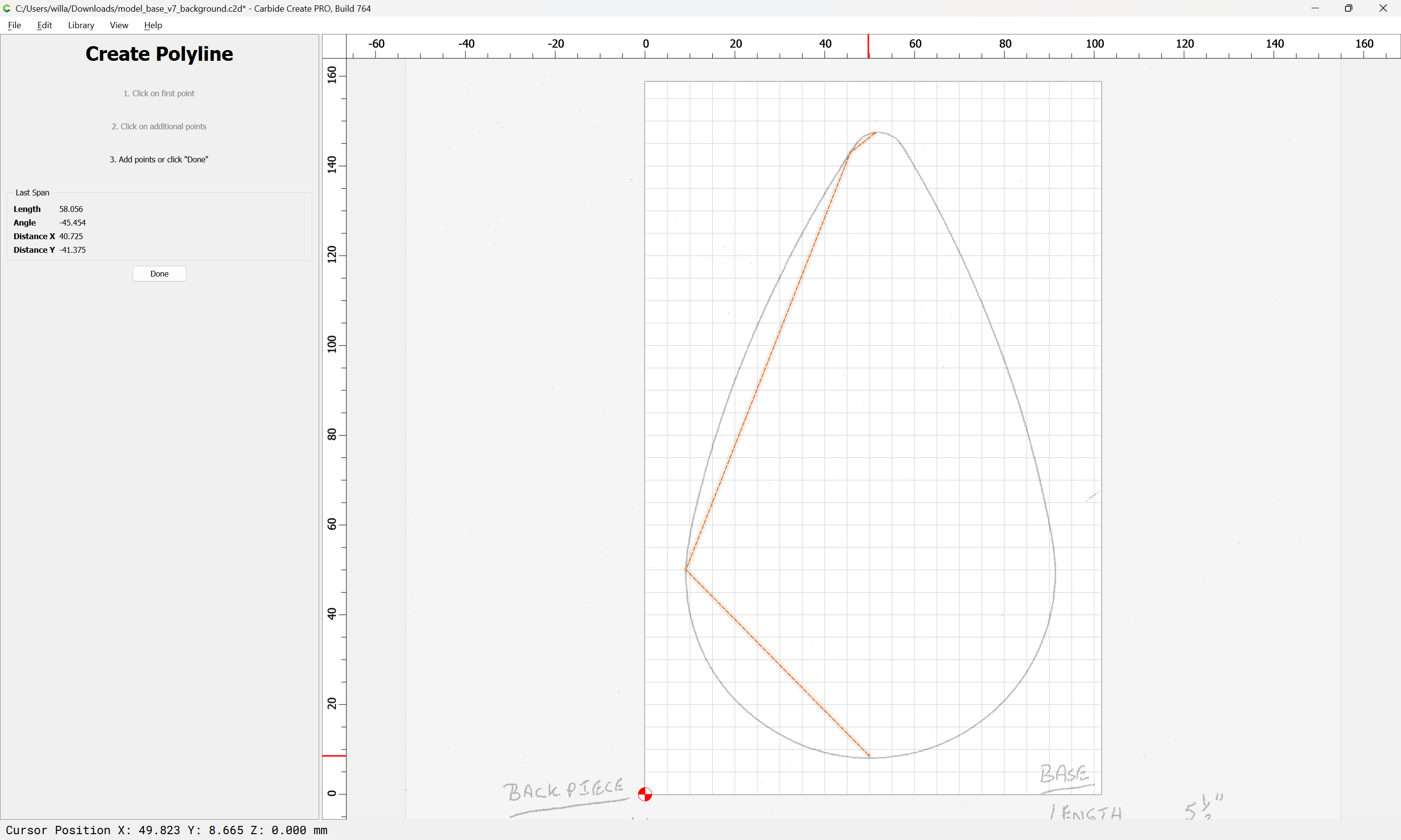
begin dragging the off-curve nodes to adjust the shape:
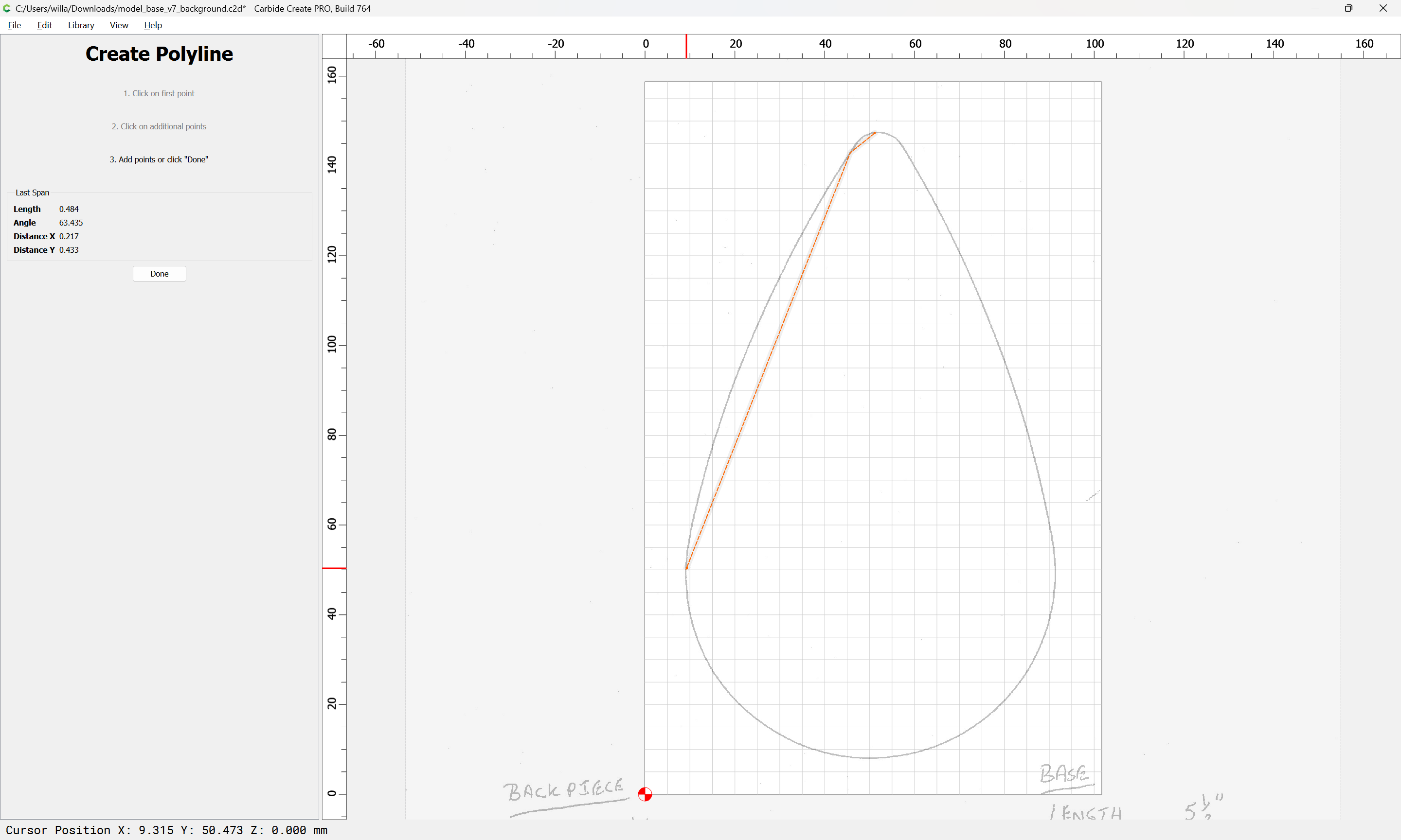
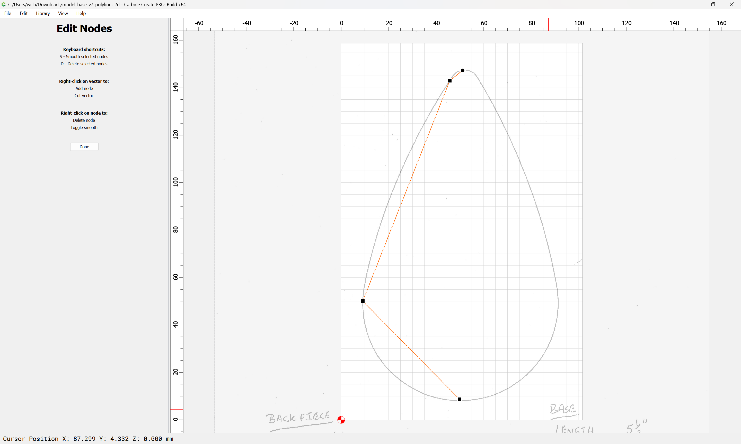
If need be, fine-tune the on-curve node position(s):
and then continue adjusting the on-curve nodes until one arrives at:
(resist the urge to add an additional node along a curve unless necessary)
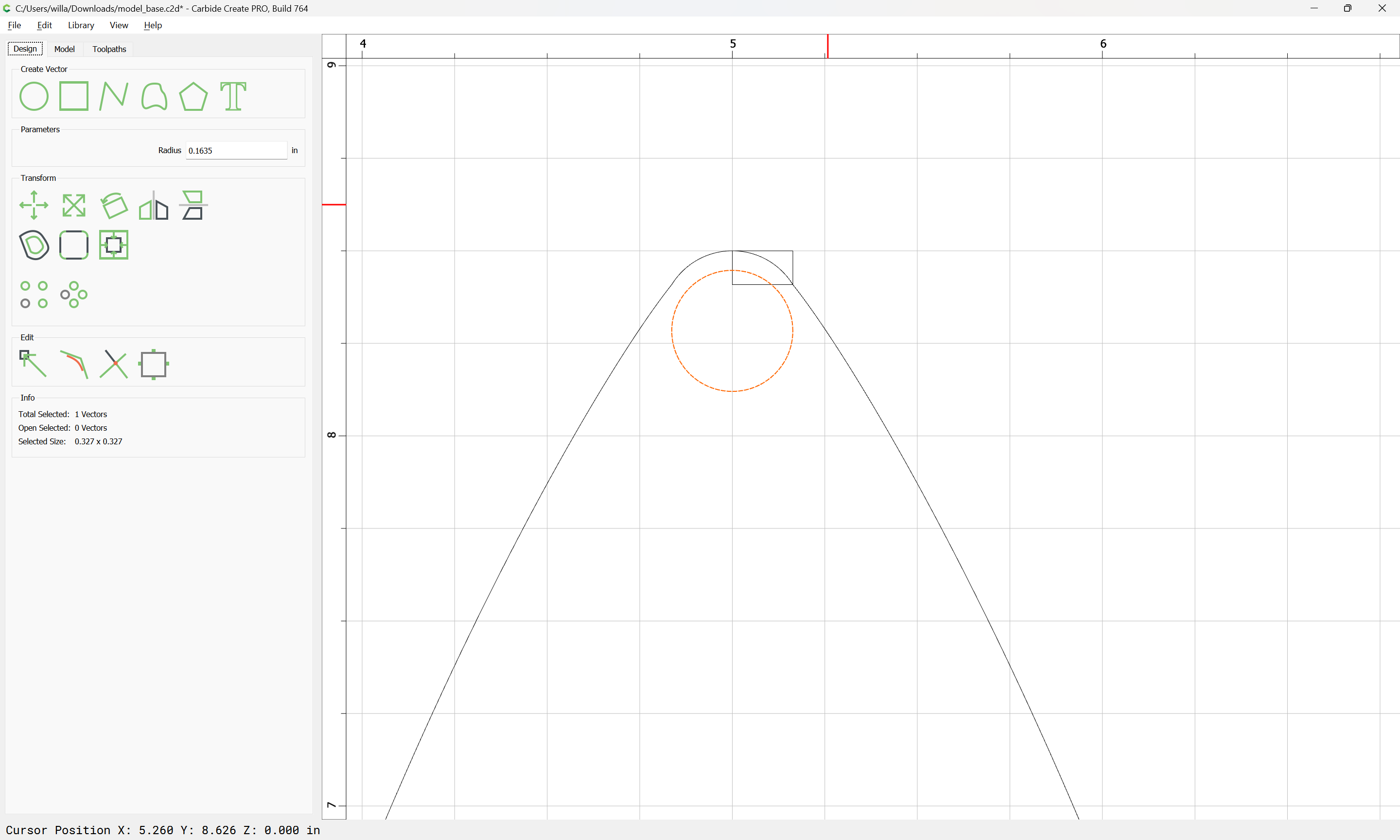
zoom out:
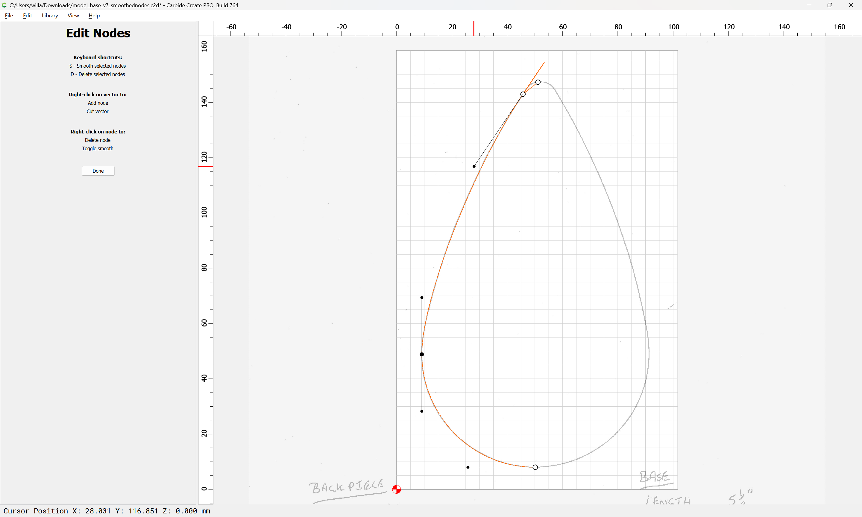
and begin adjusting the next section:
which seems good when zoomed in a bit:
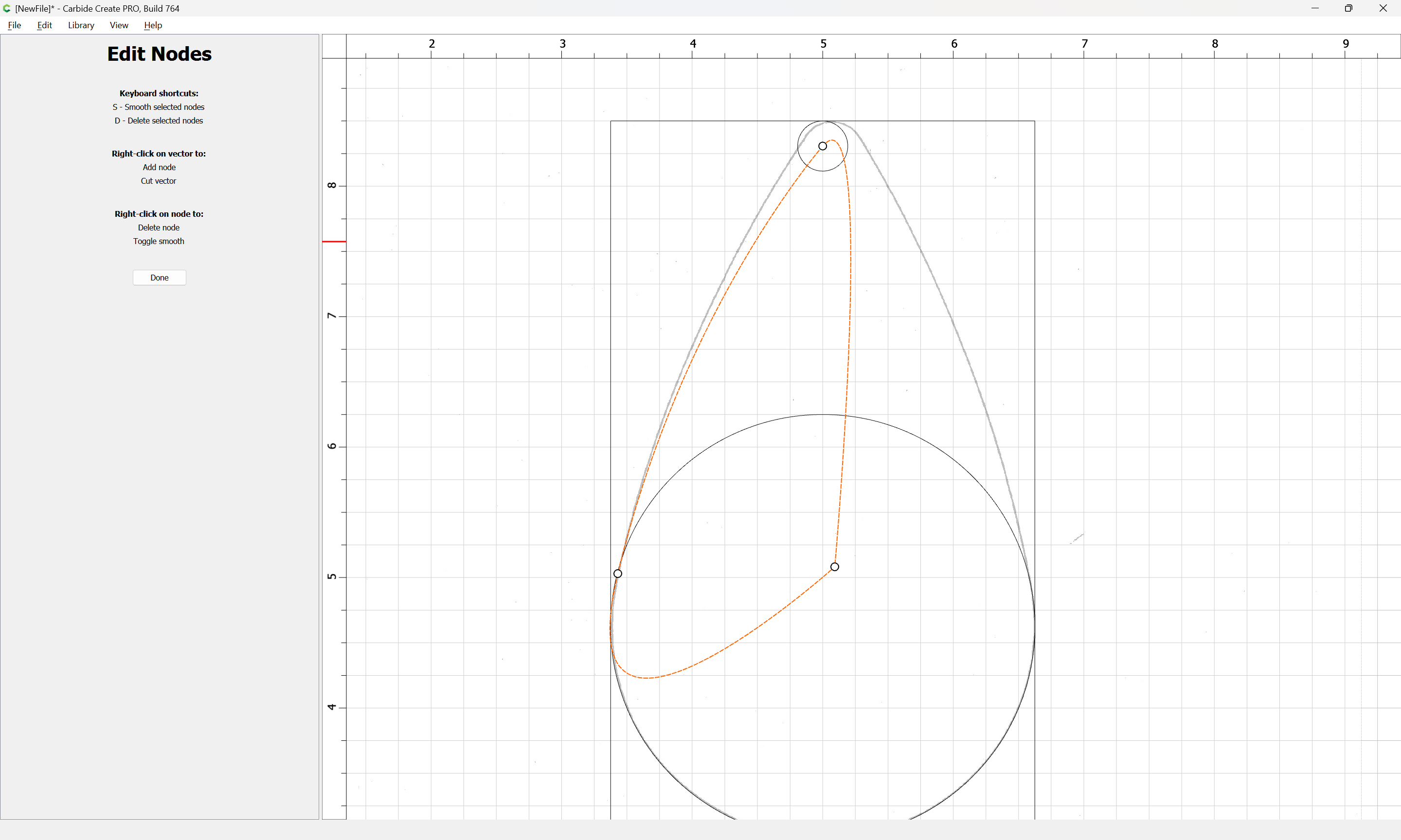
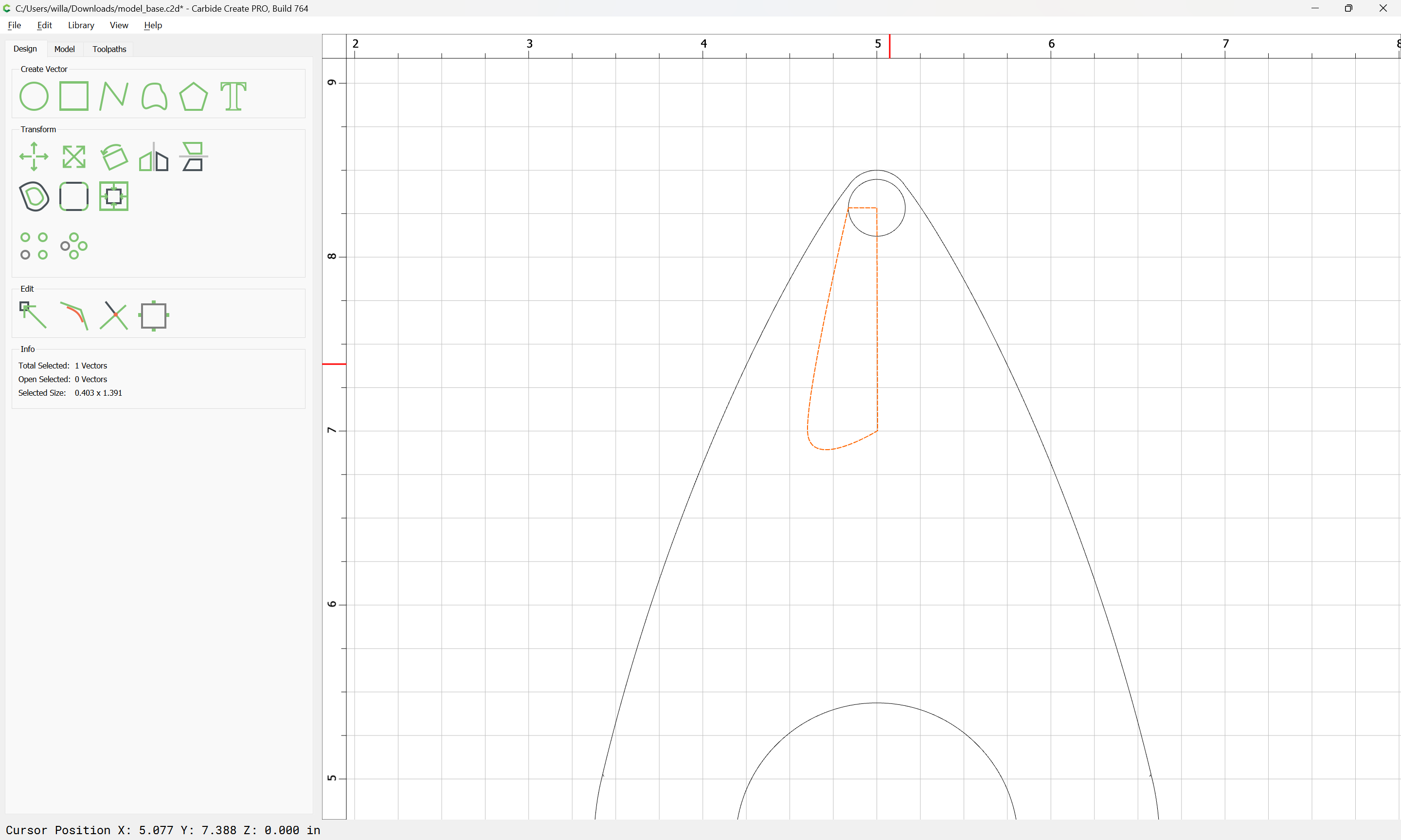
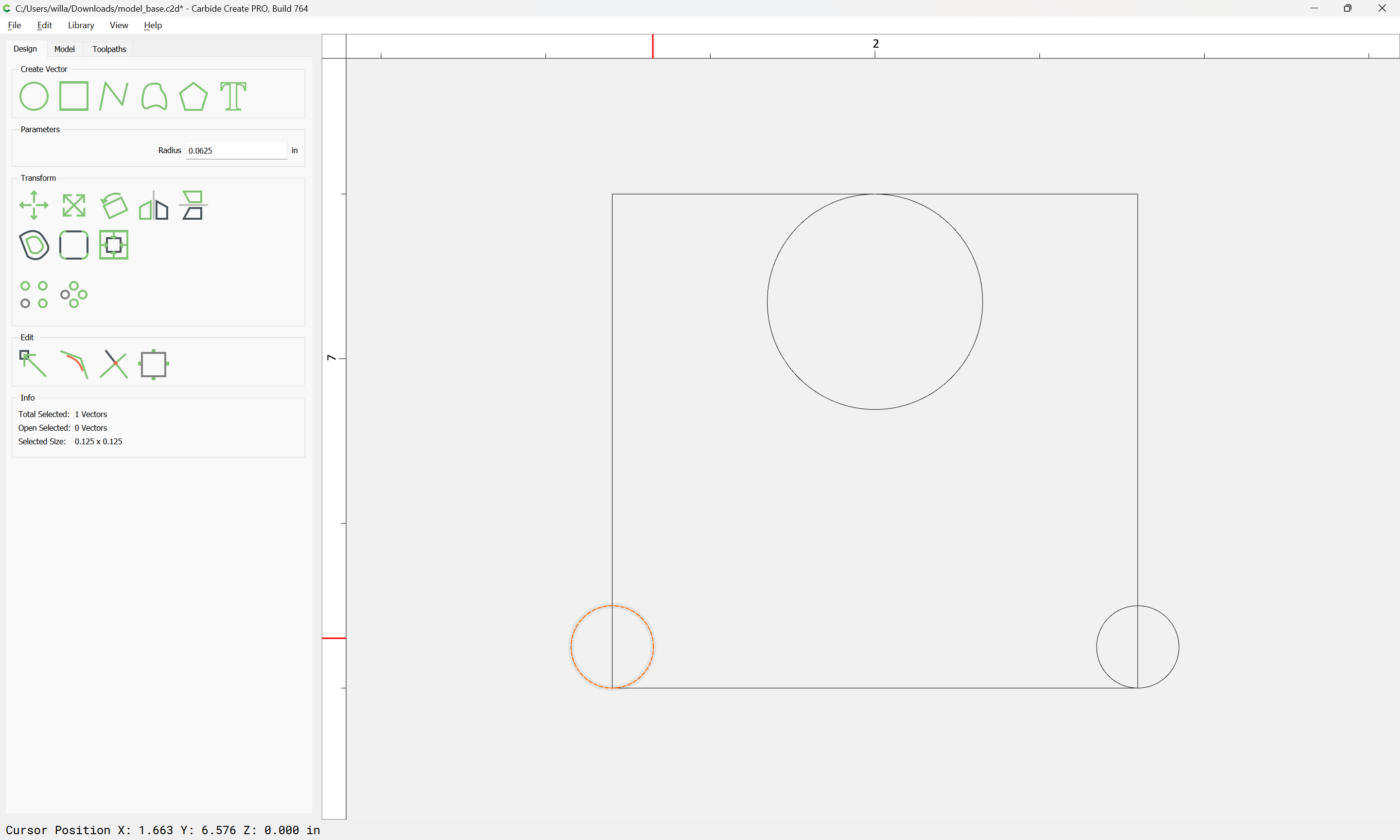
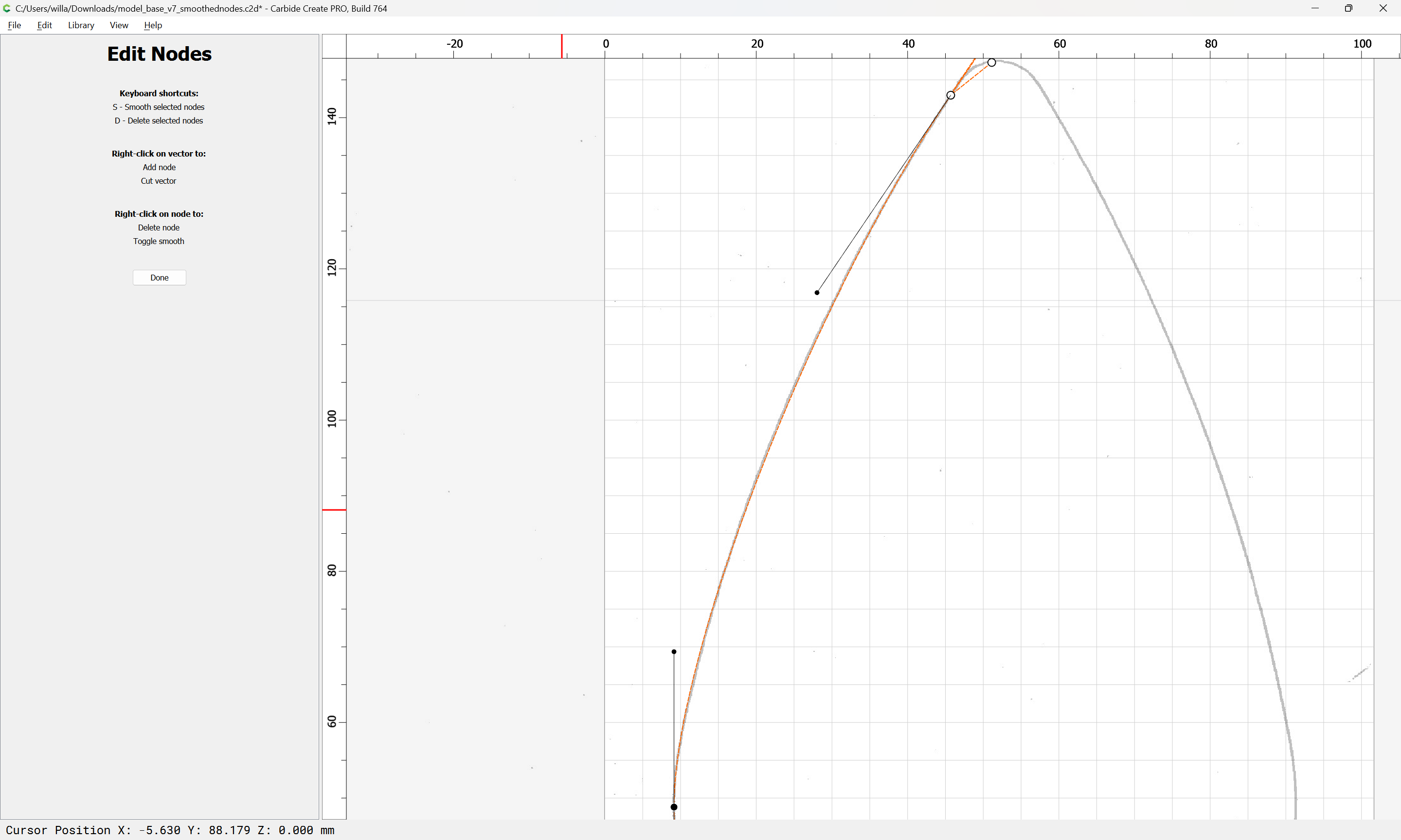
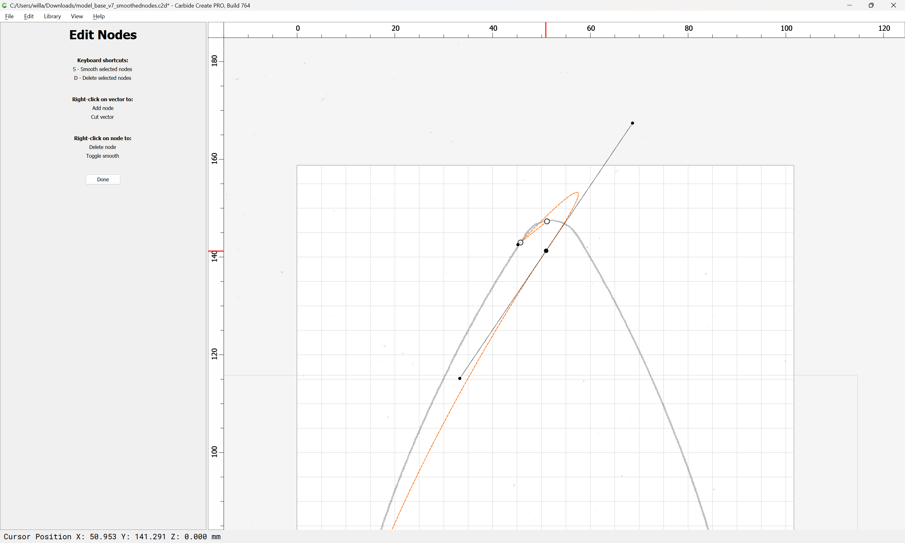
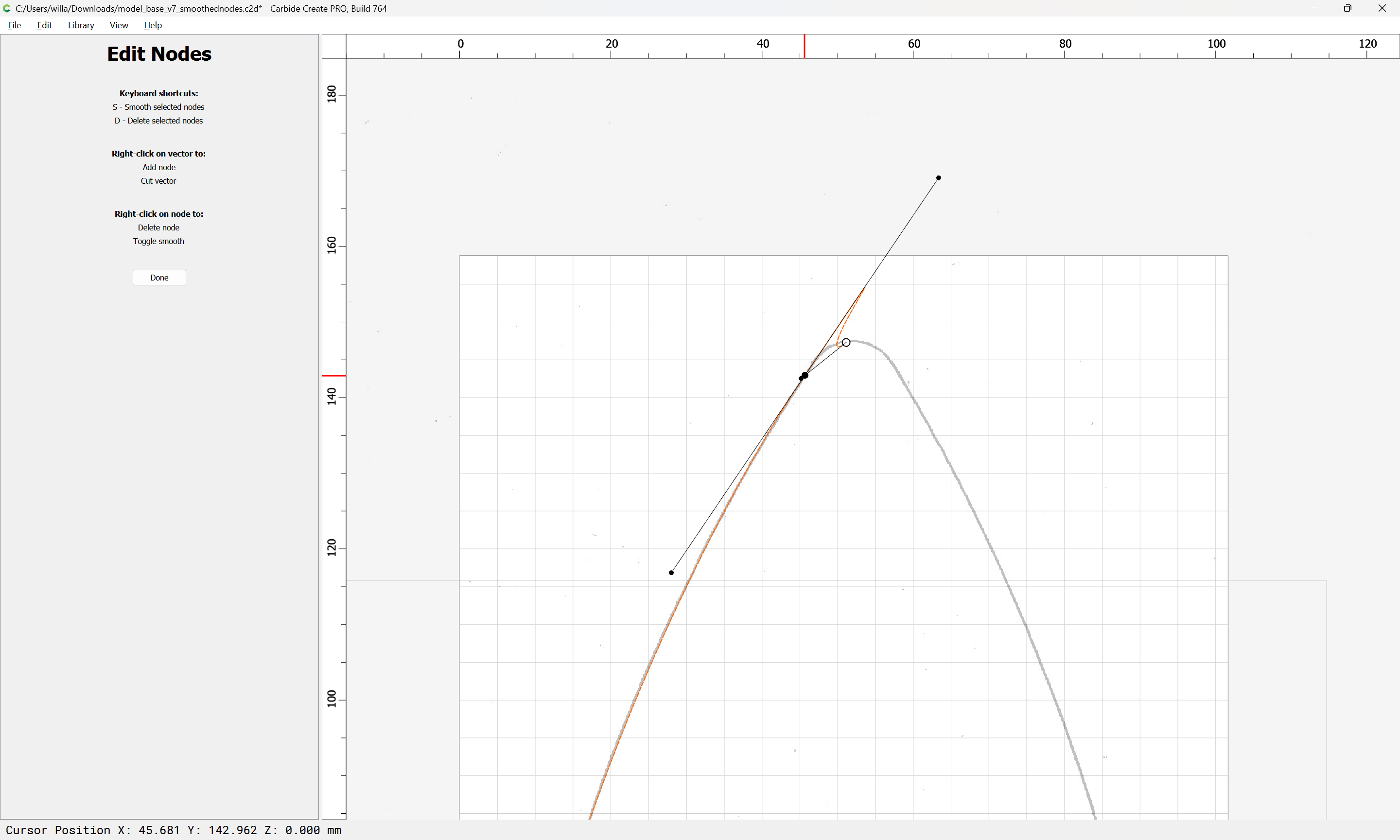
so we move on to the last segment:
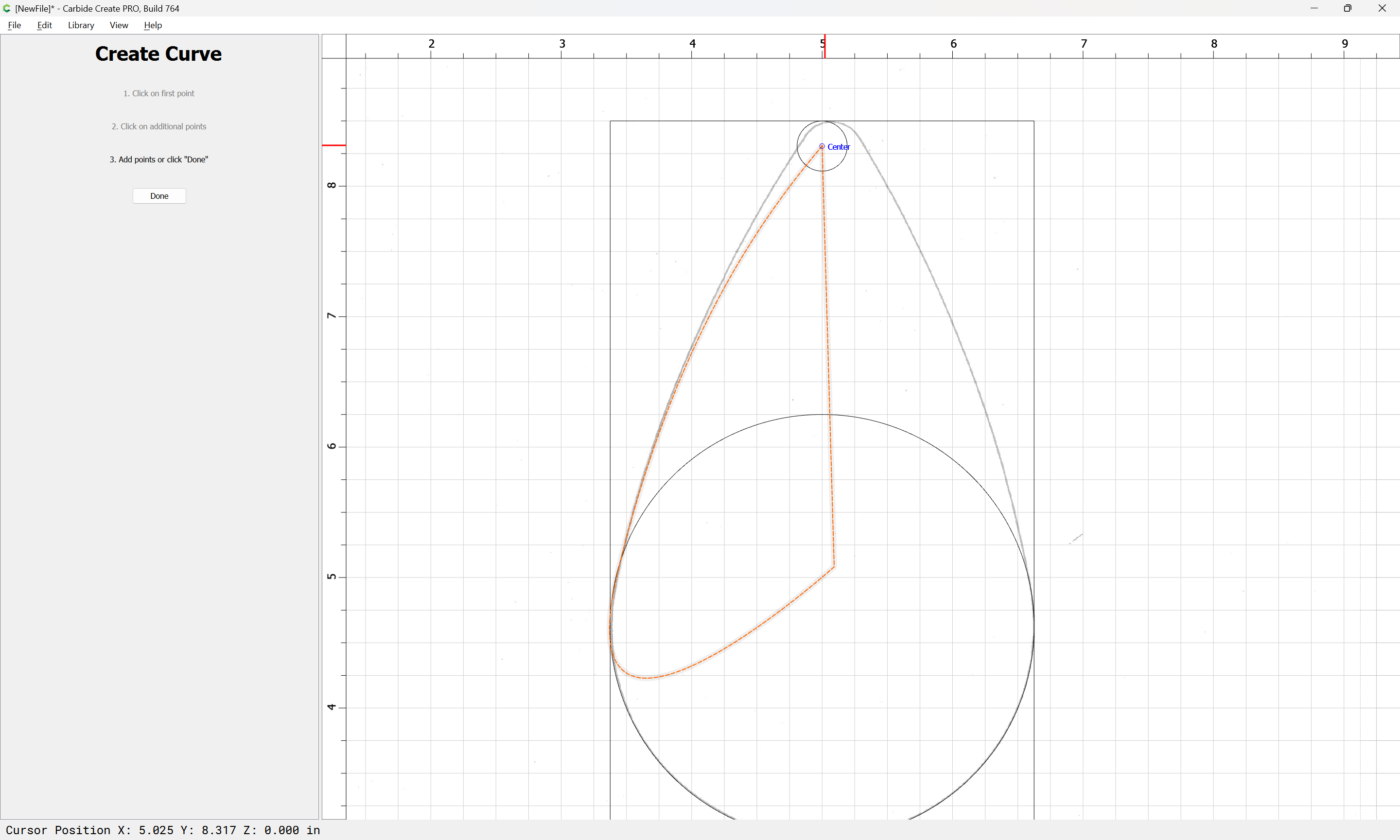
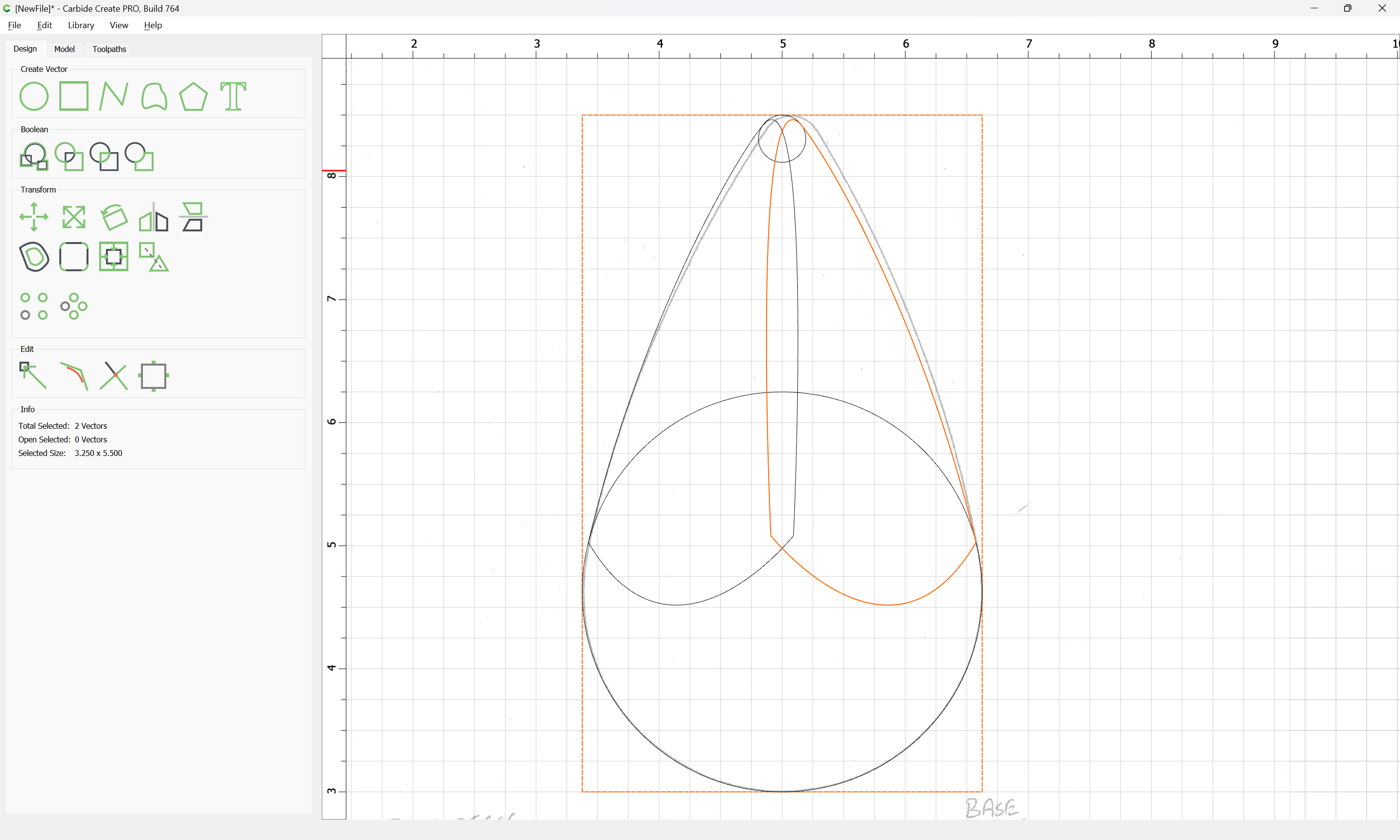
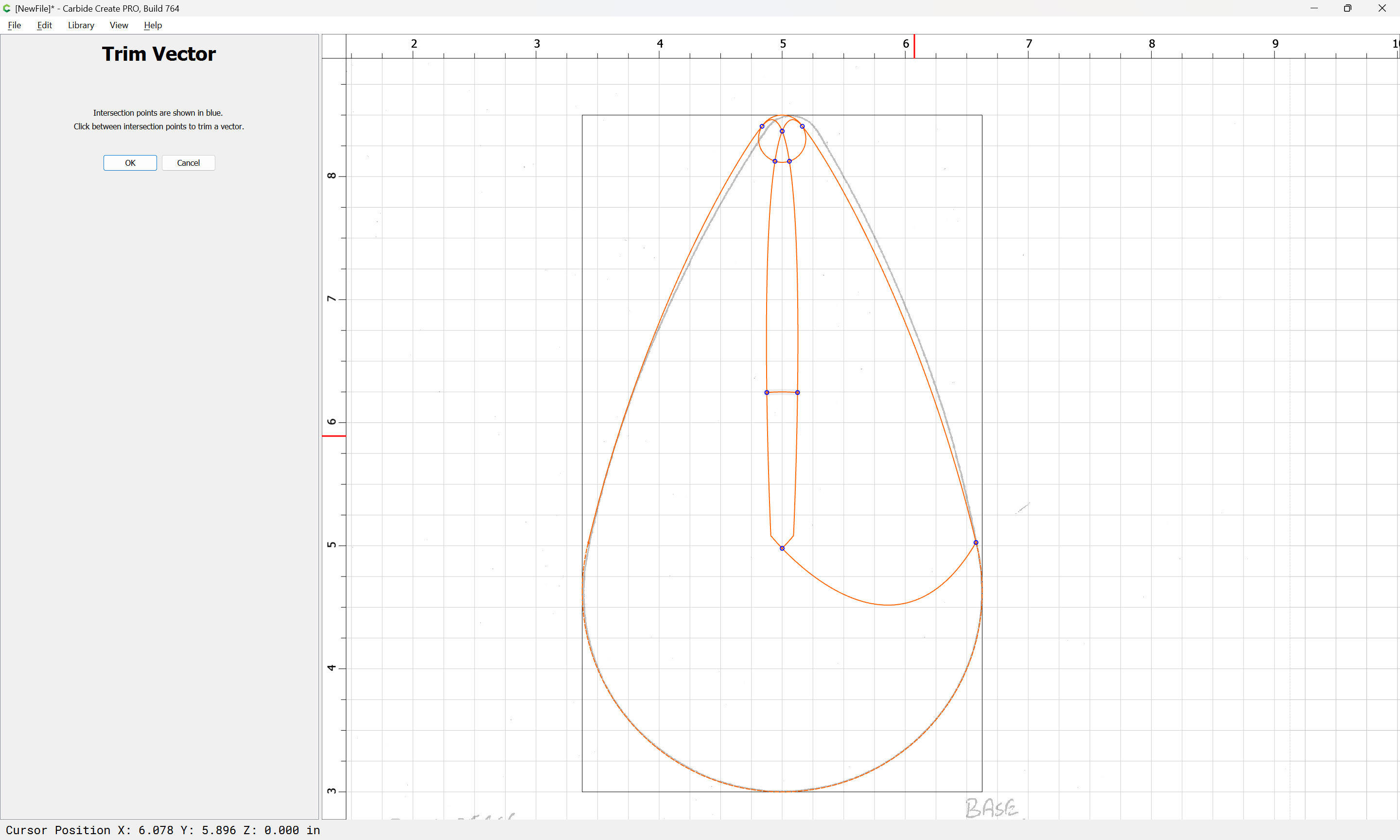
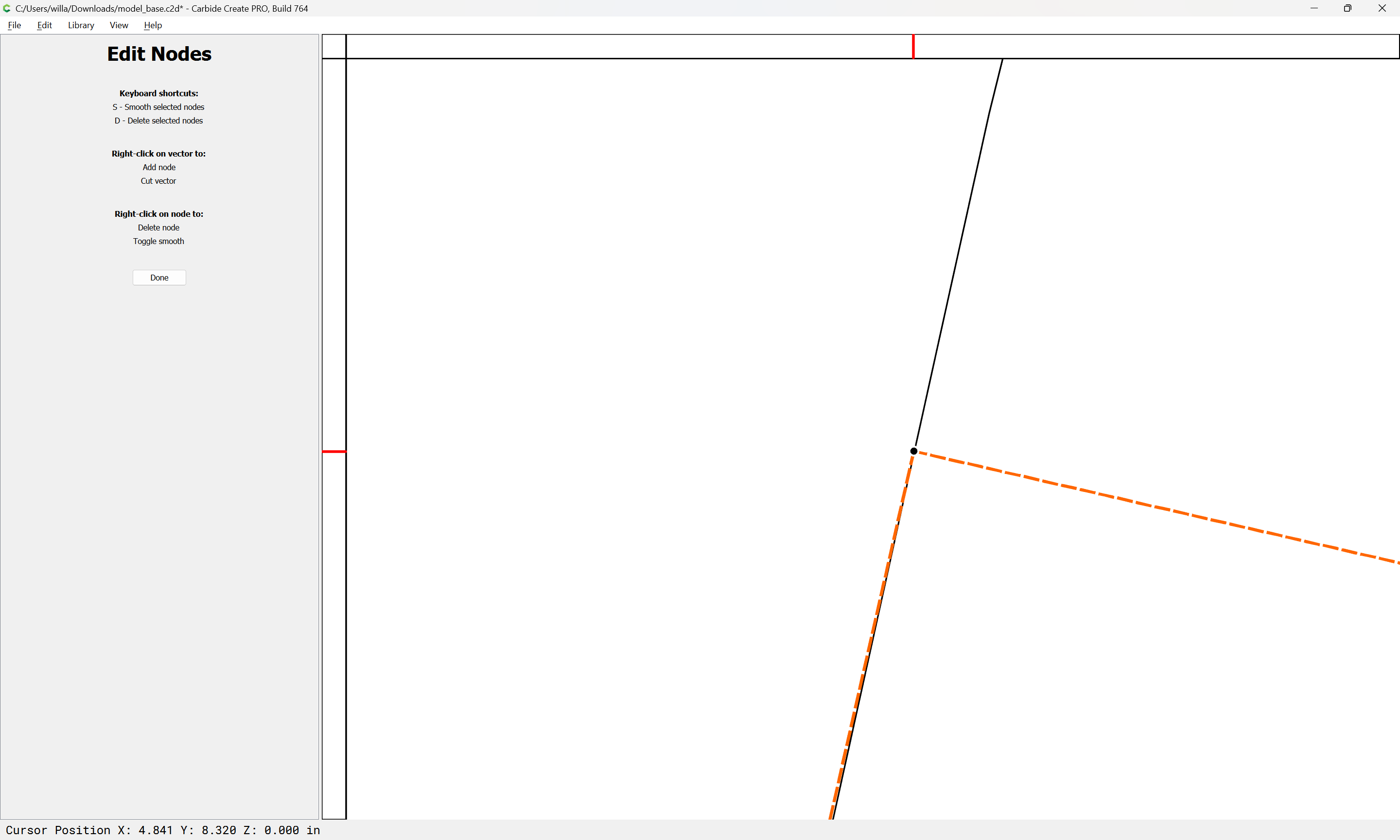
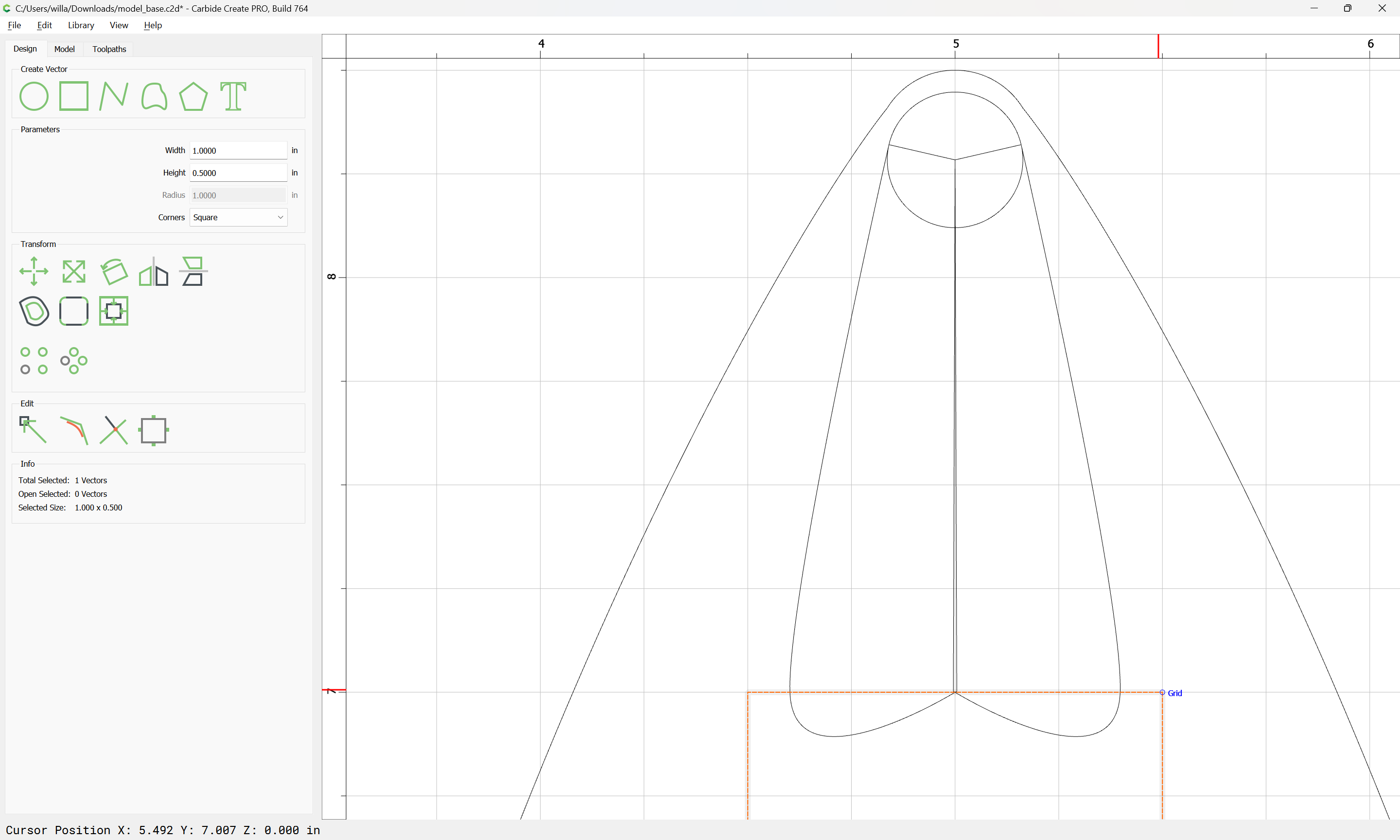
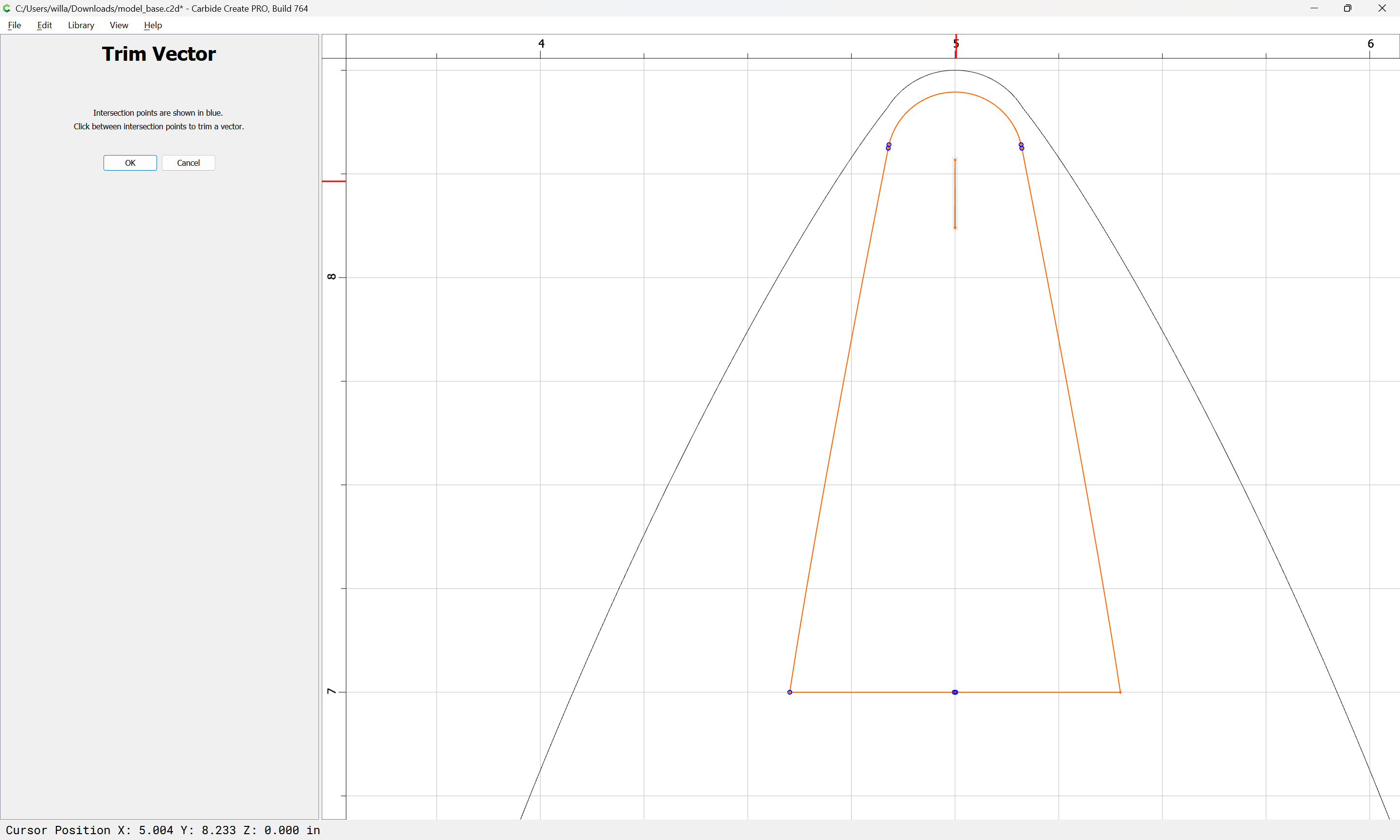
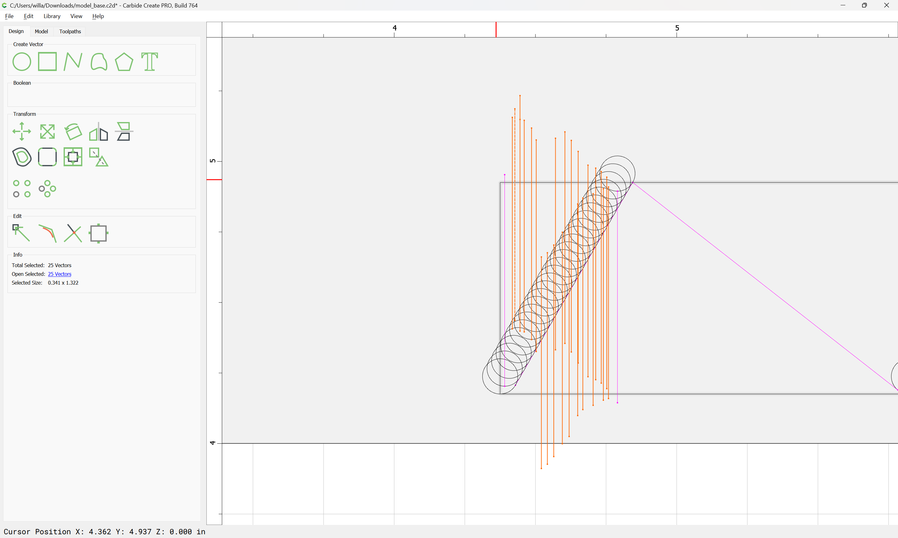
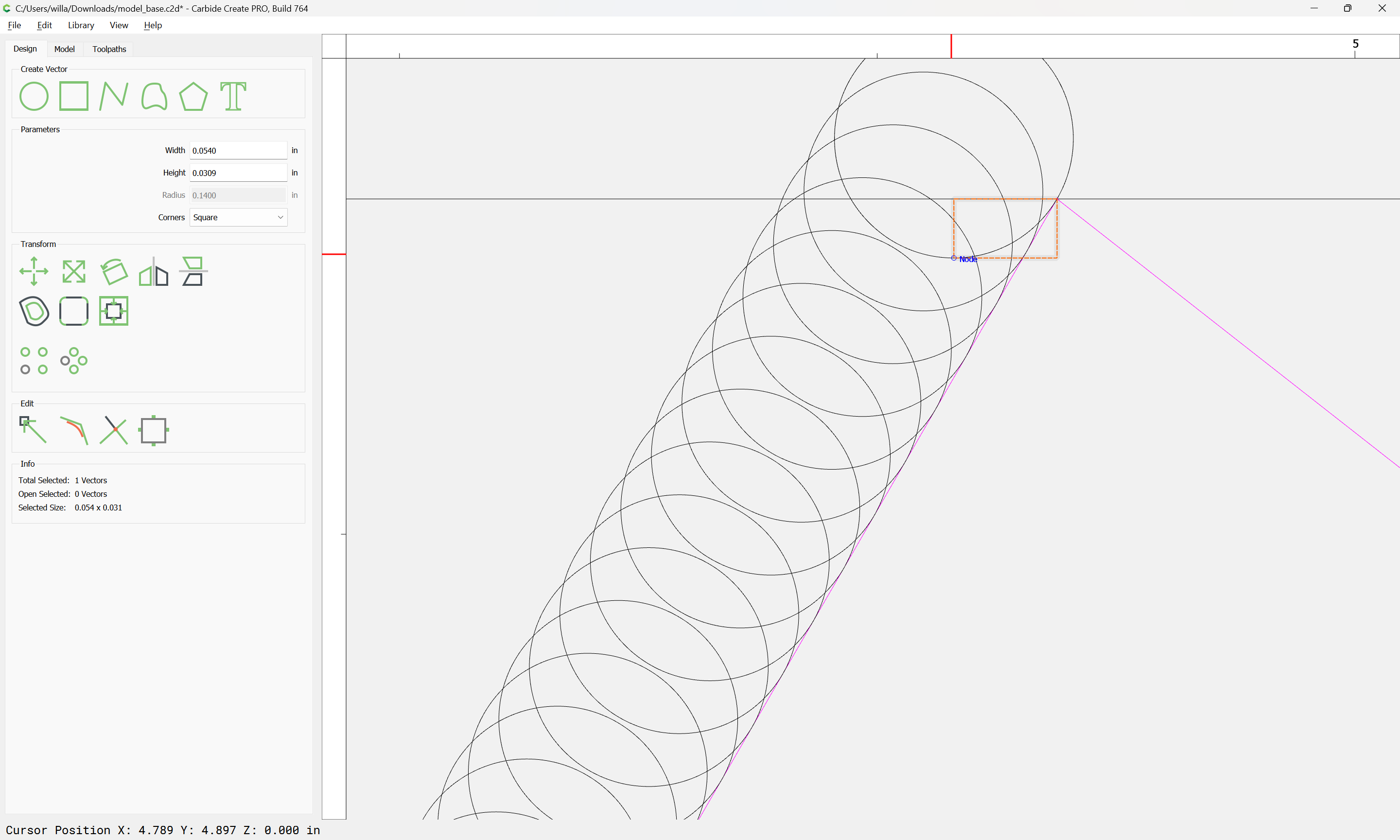
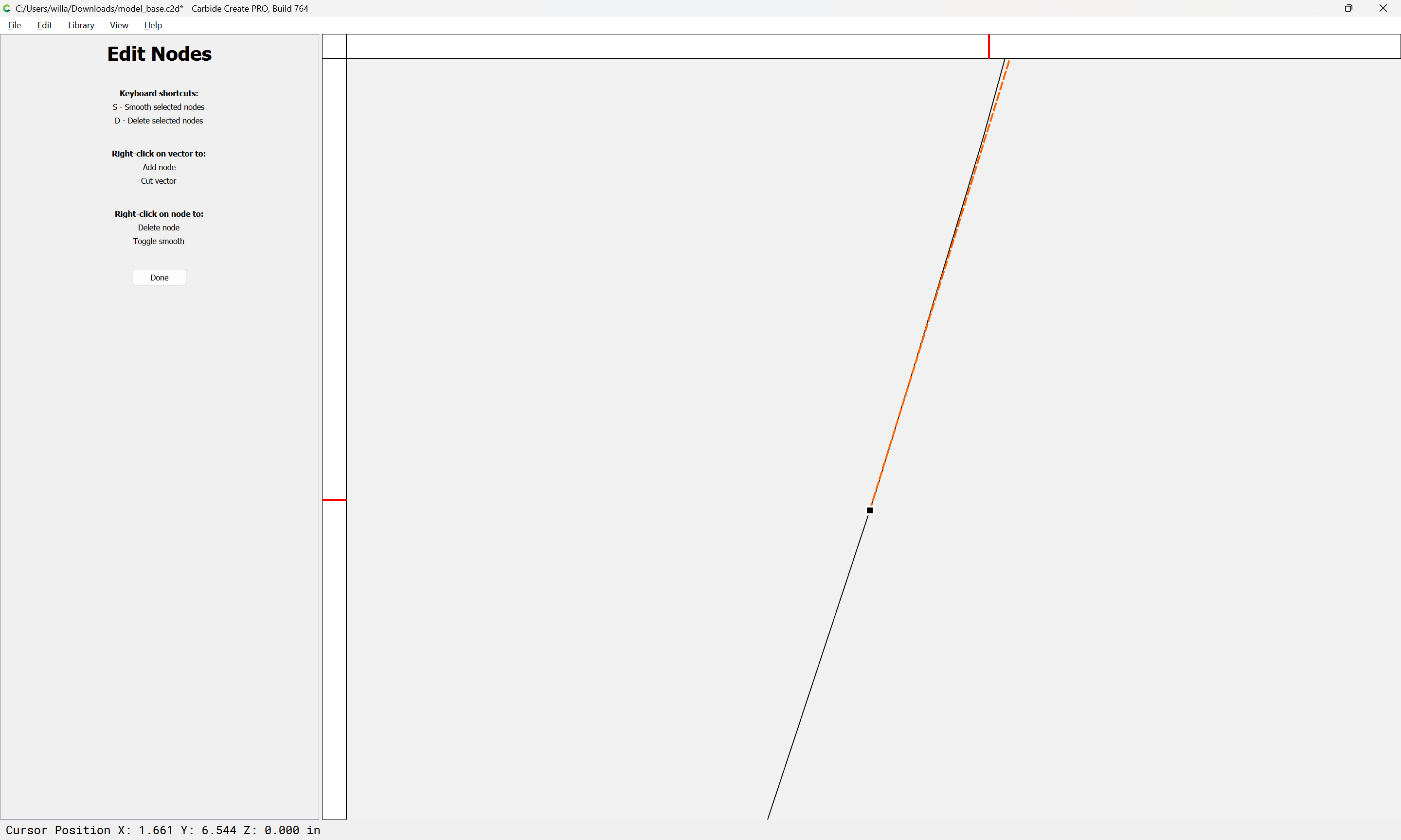
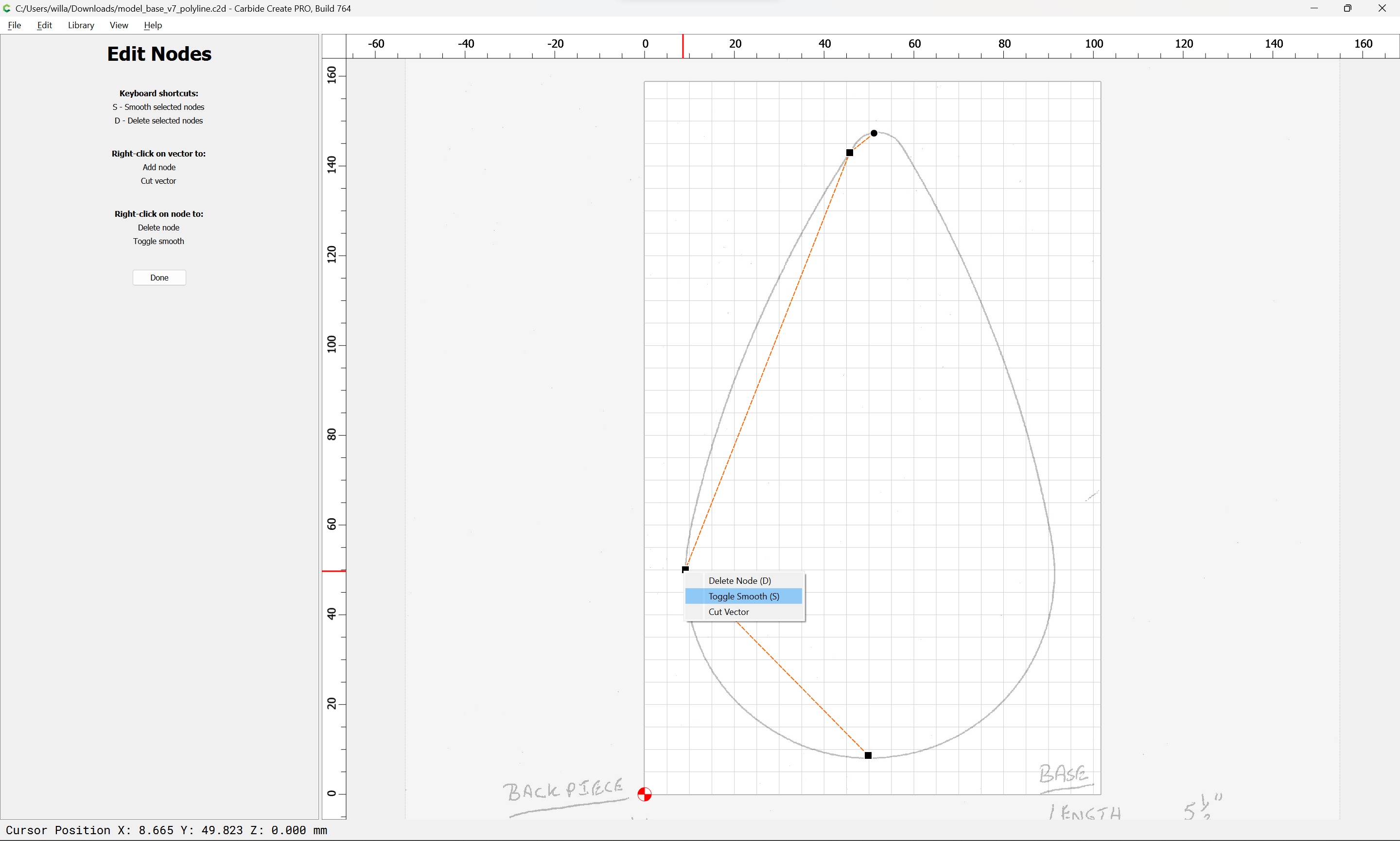
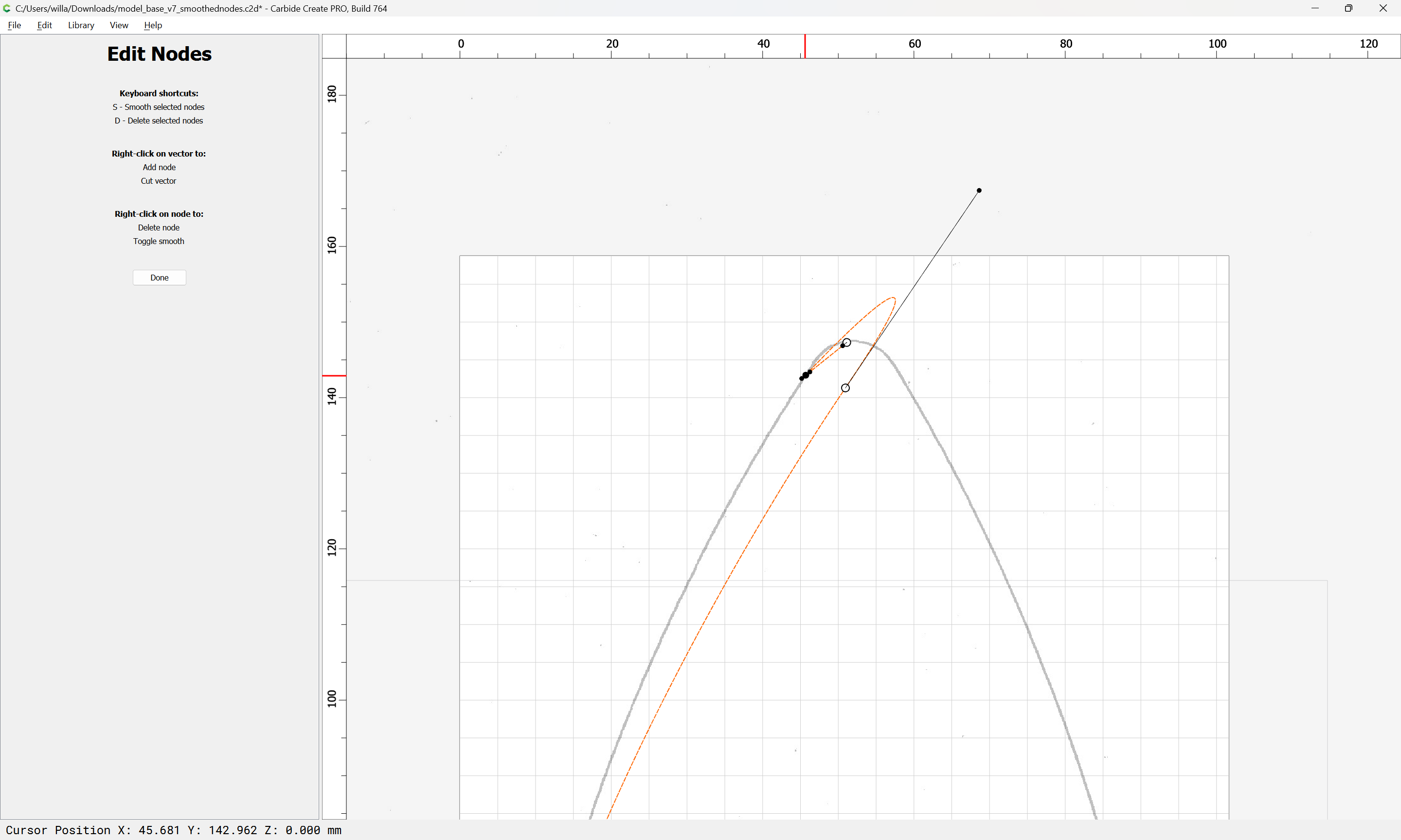
where we discover that two nodes were placed in the initial drawing
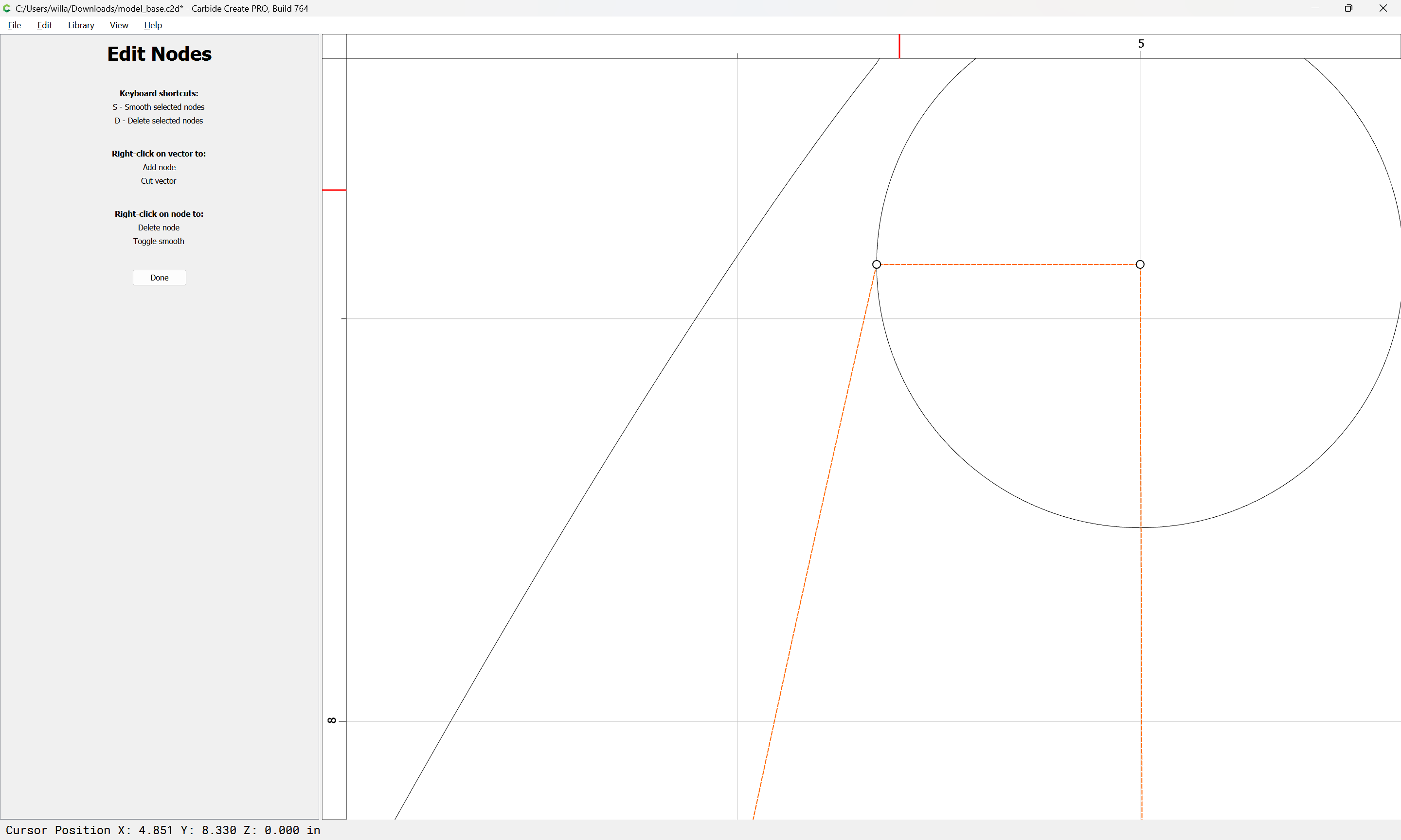
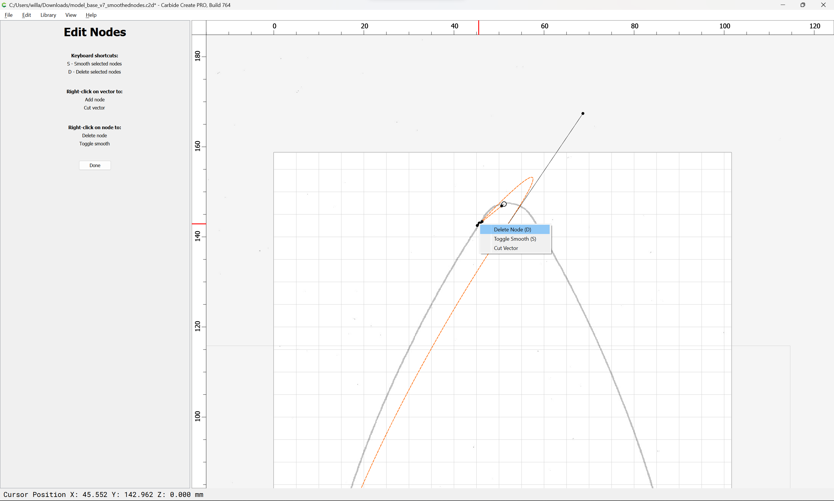
select the errant node and delete it by right-clicking and choosing Delete Node or pressing d
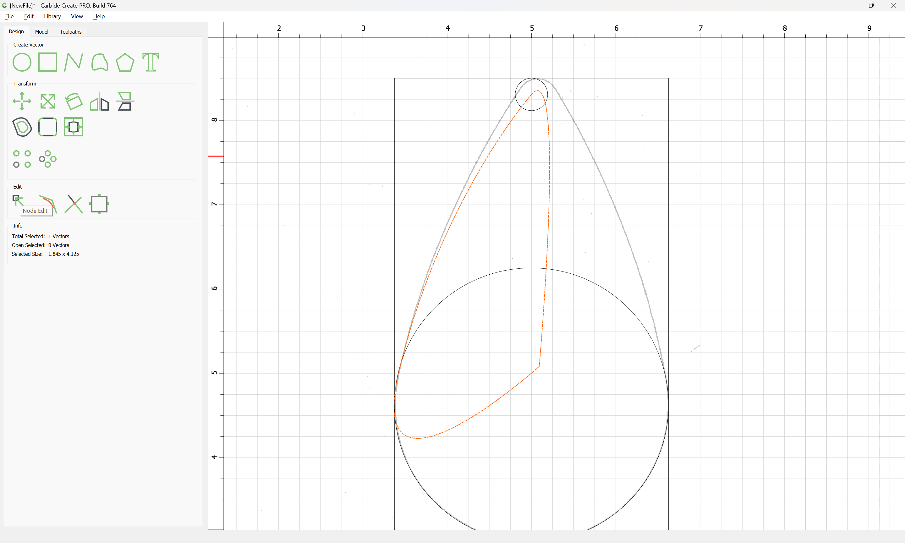
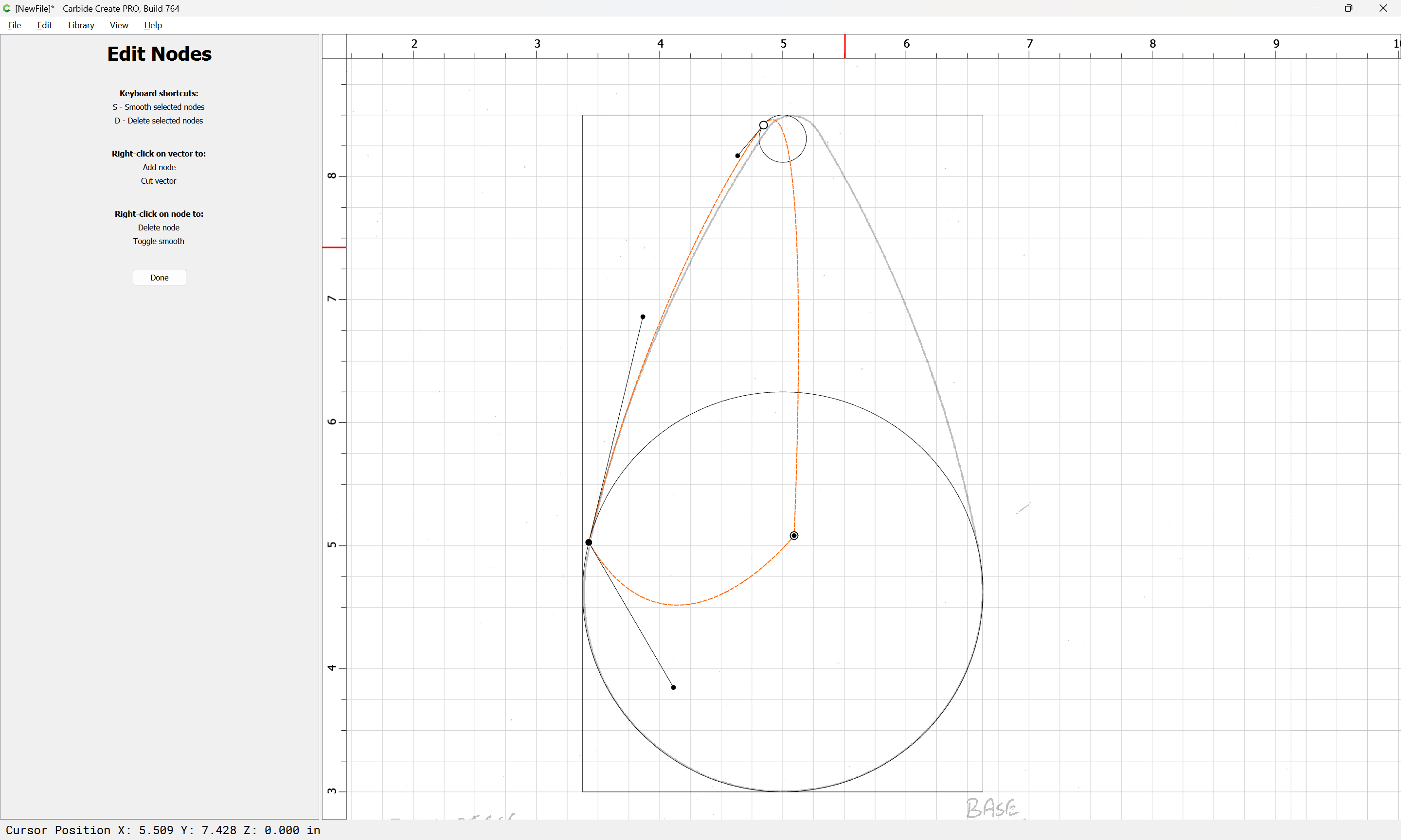
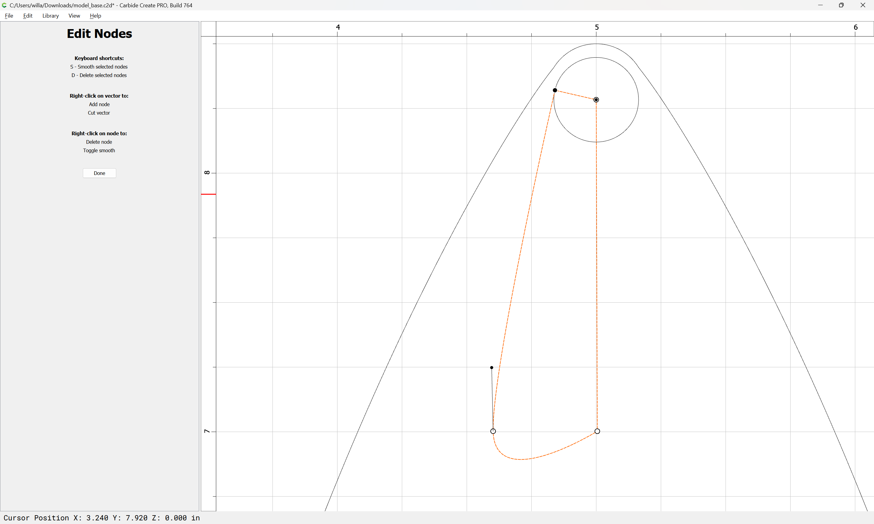
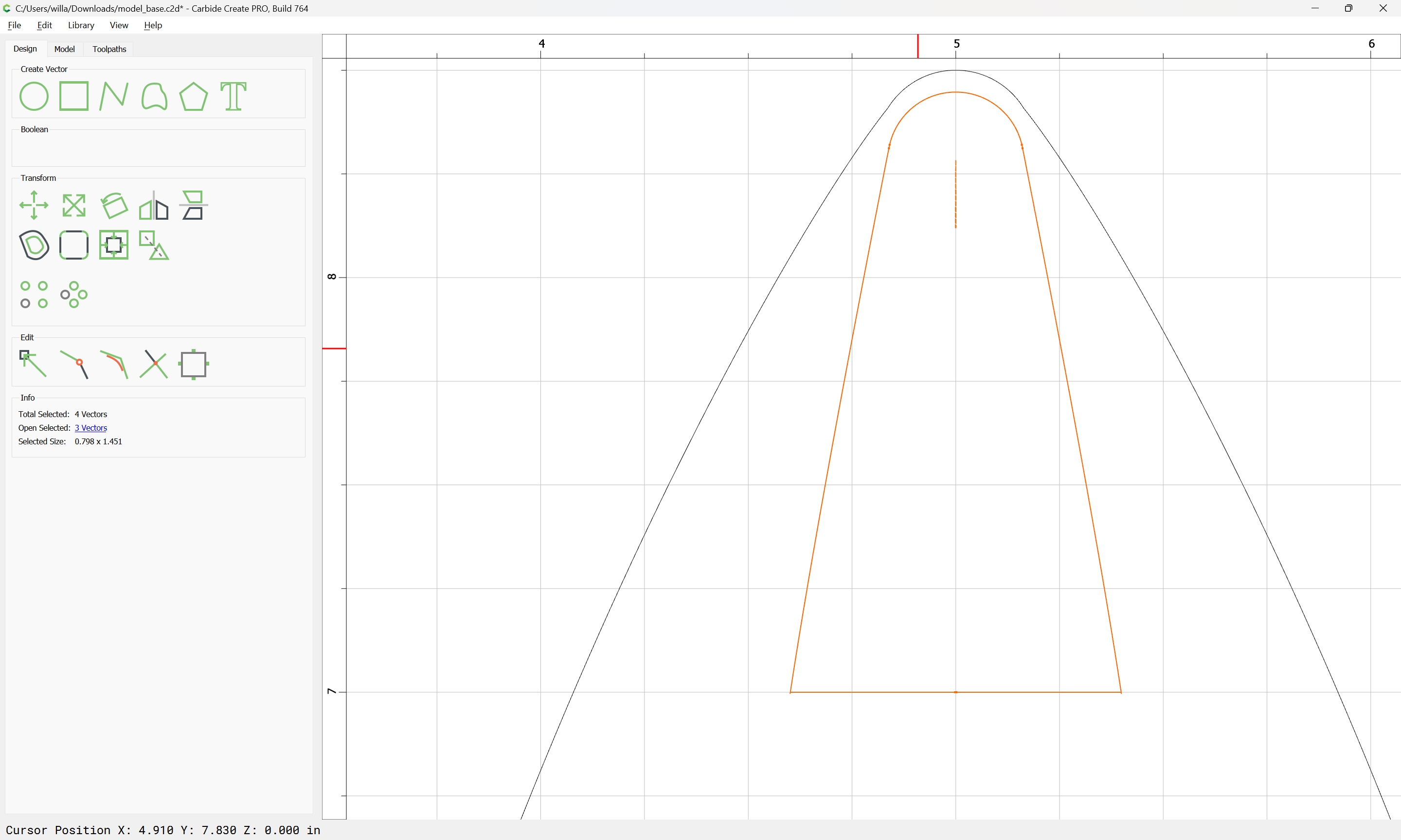
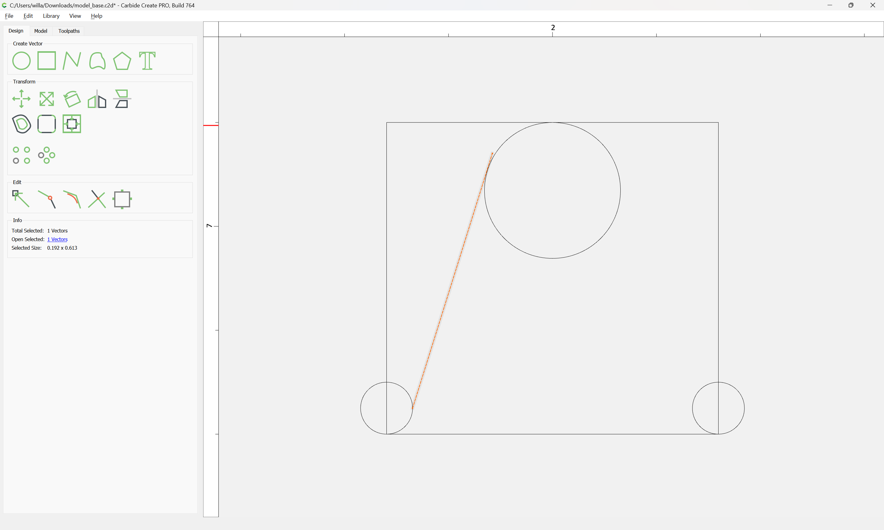
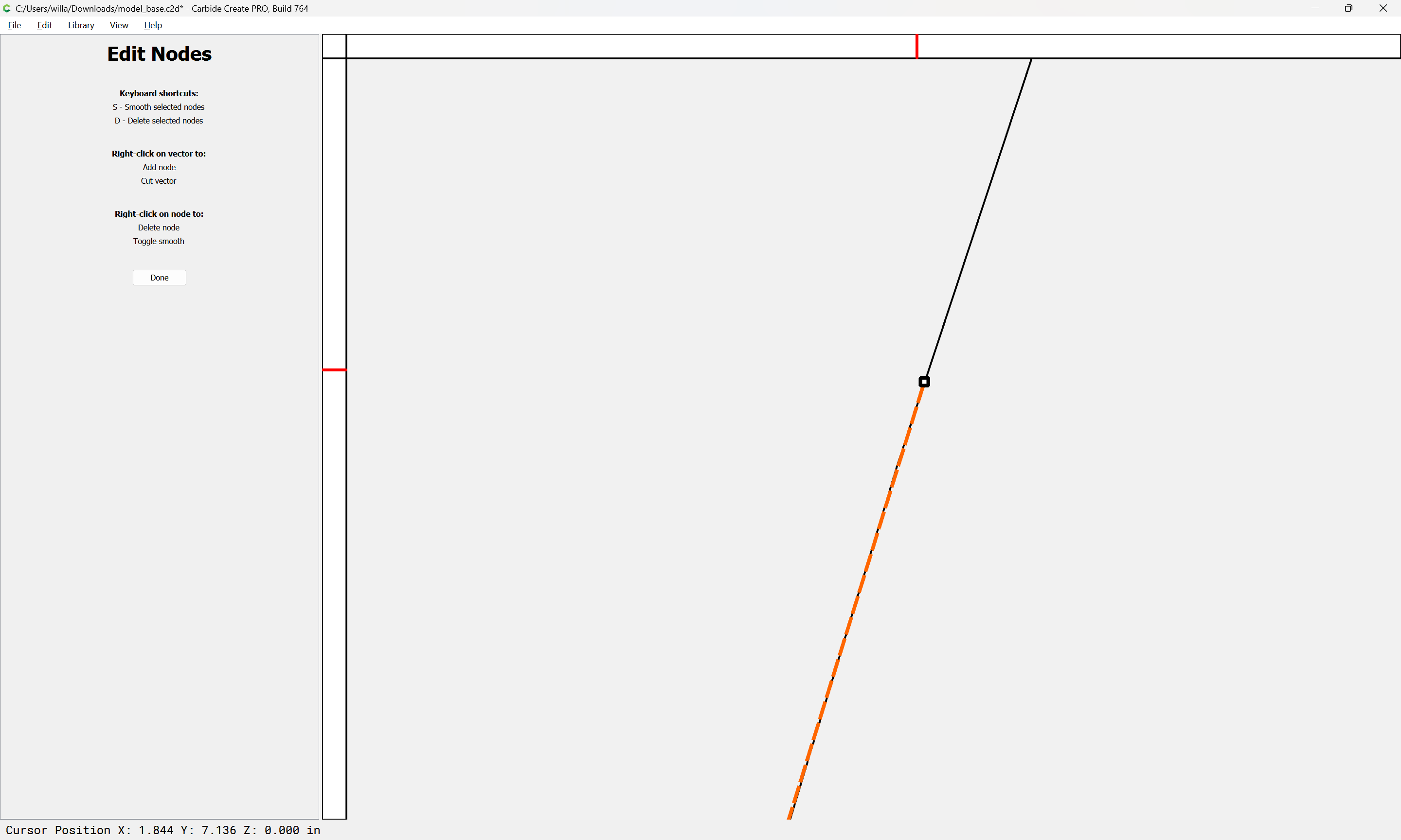
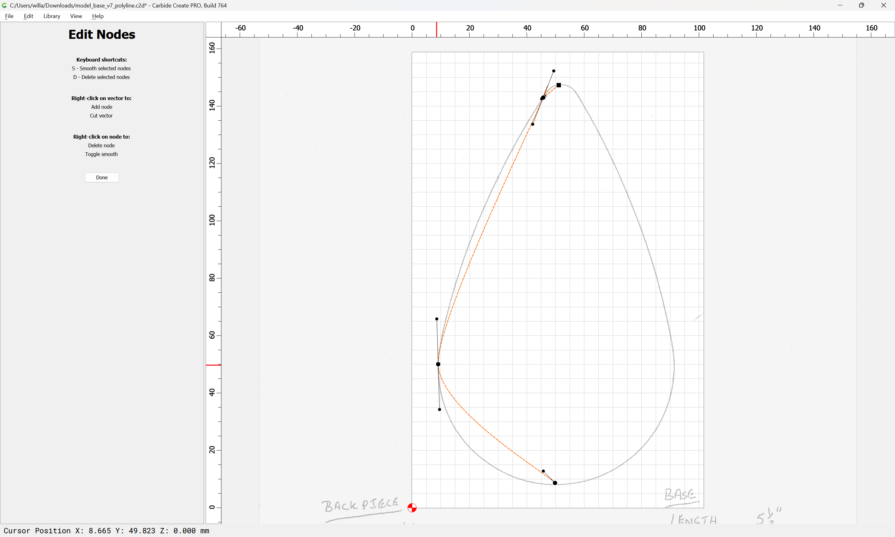
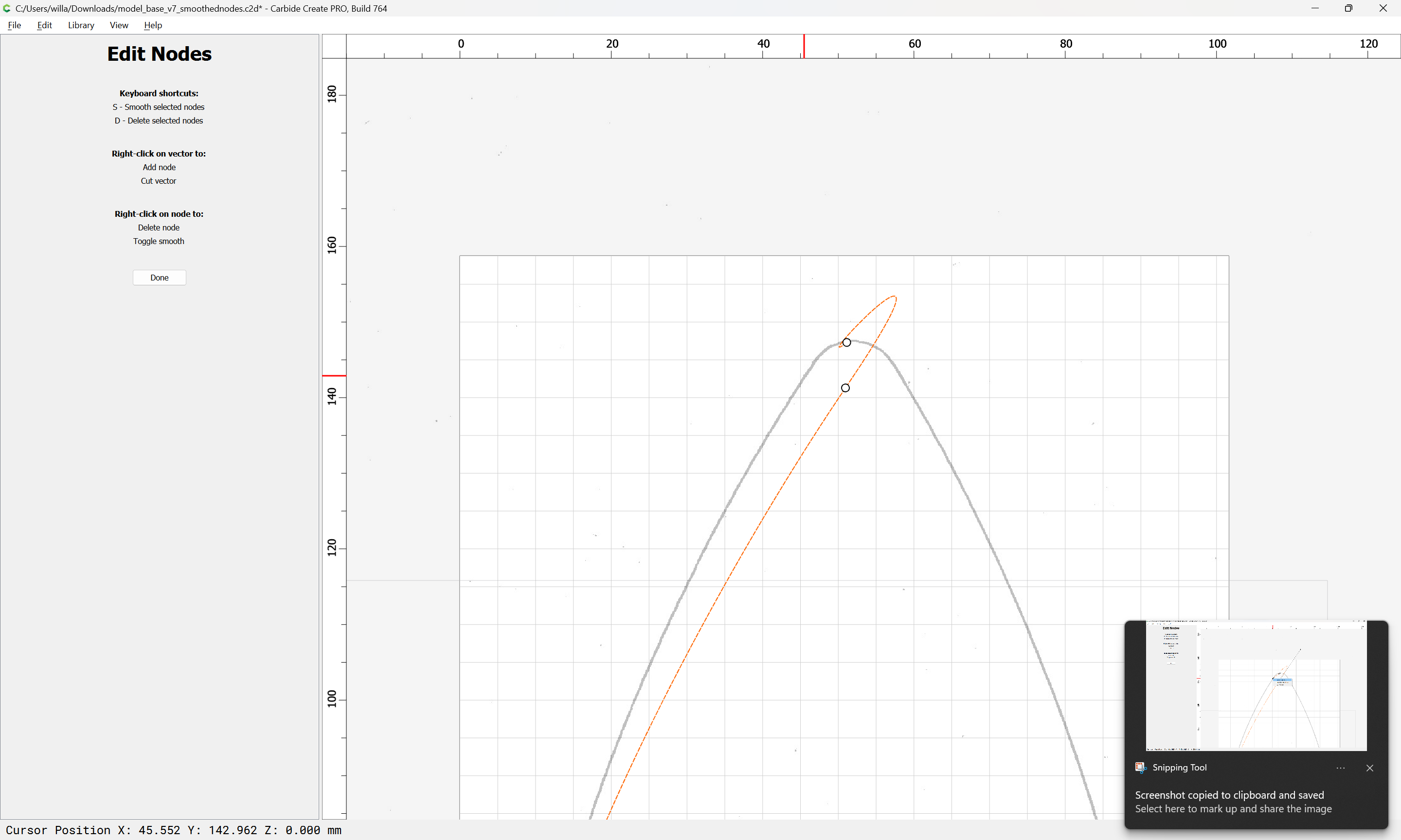
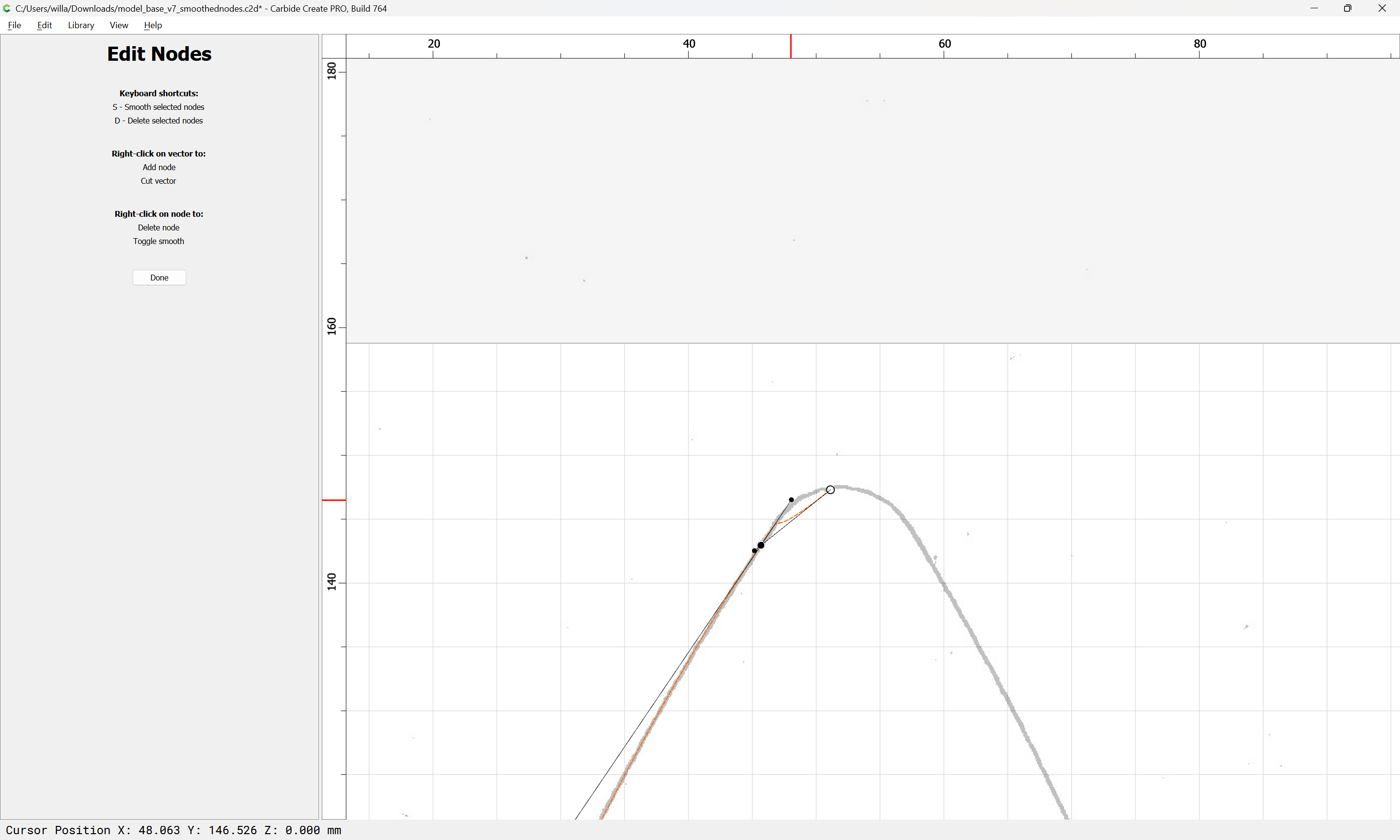
Reposition the node which was moved:
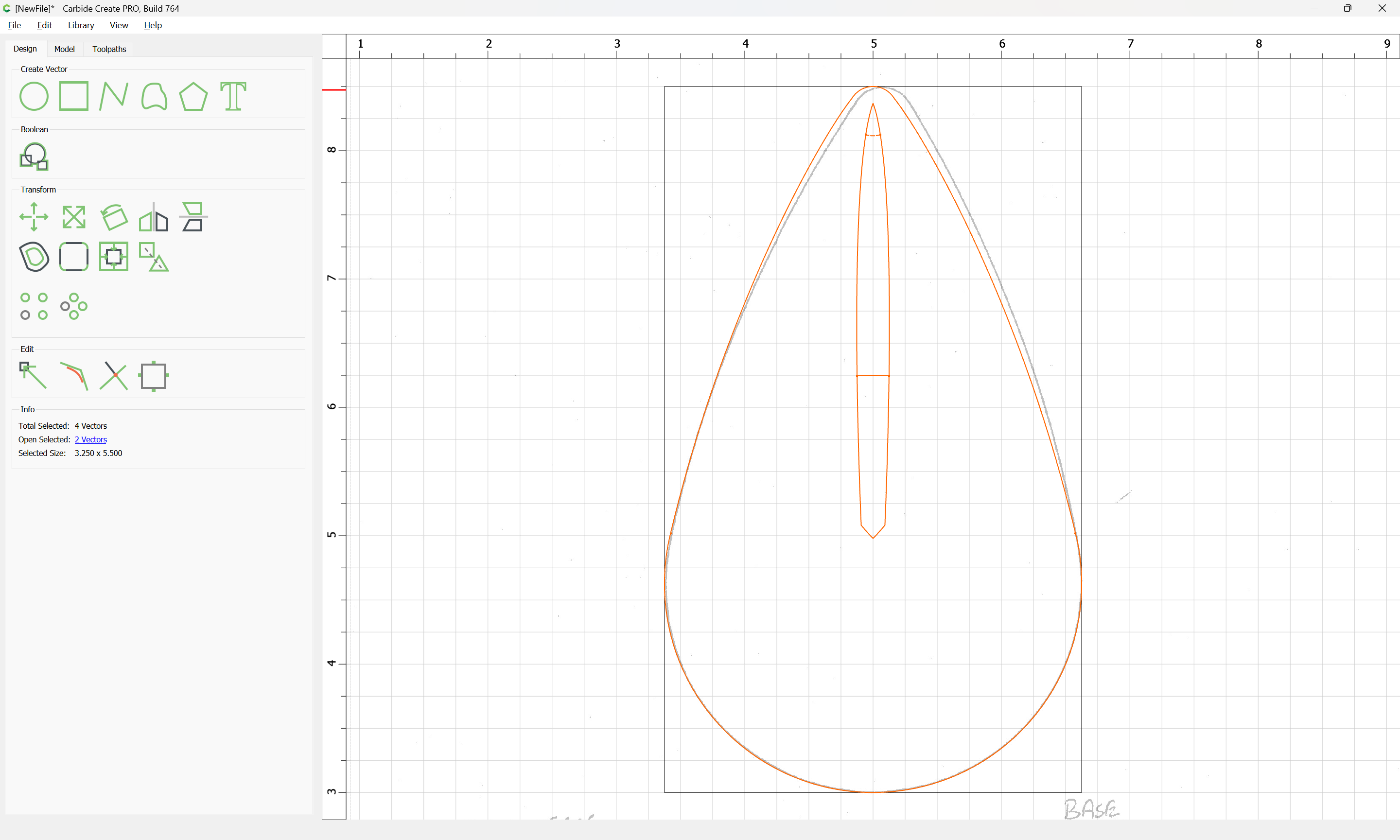
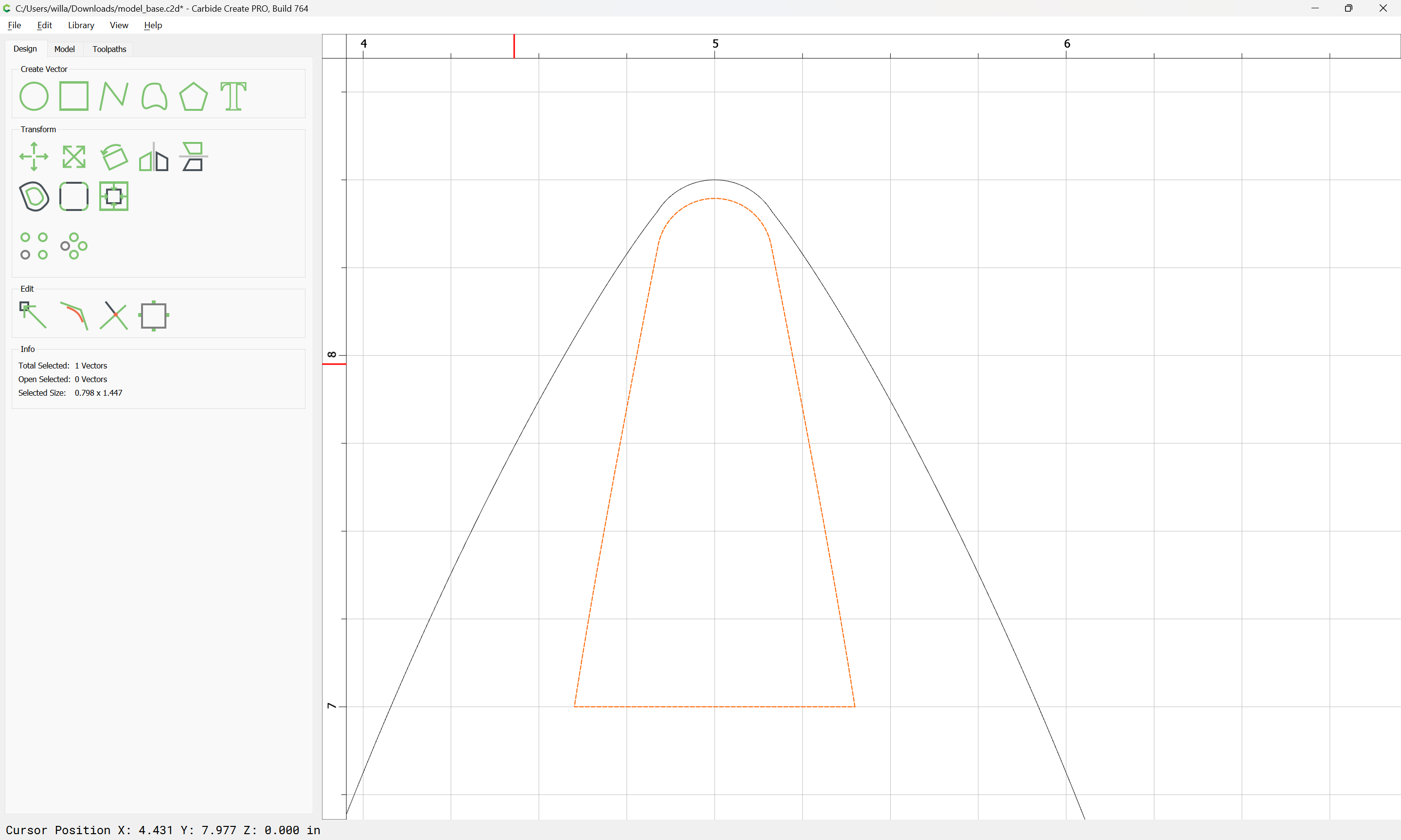
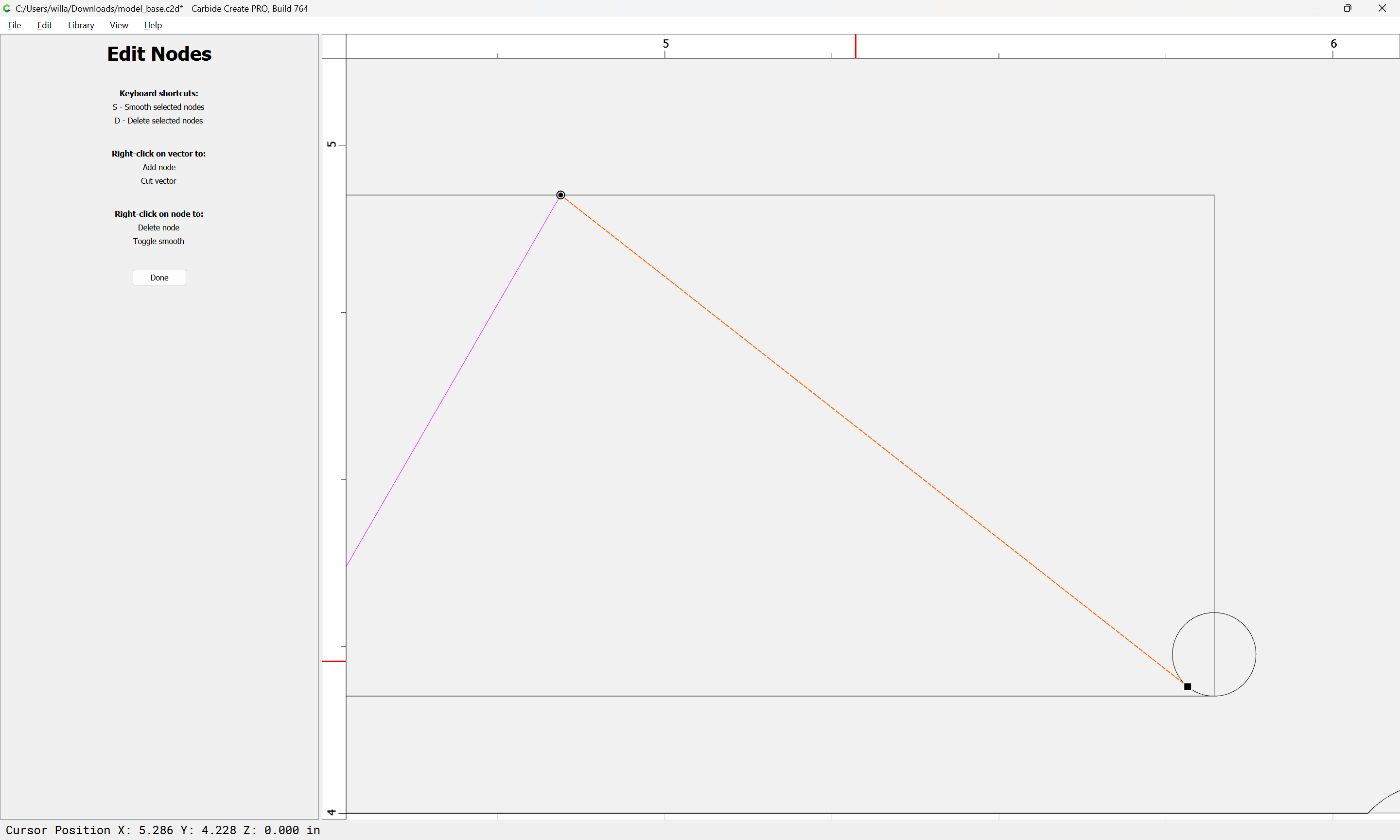
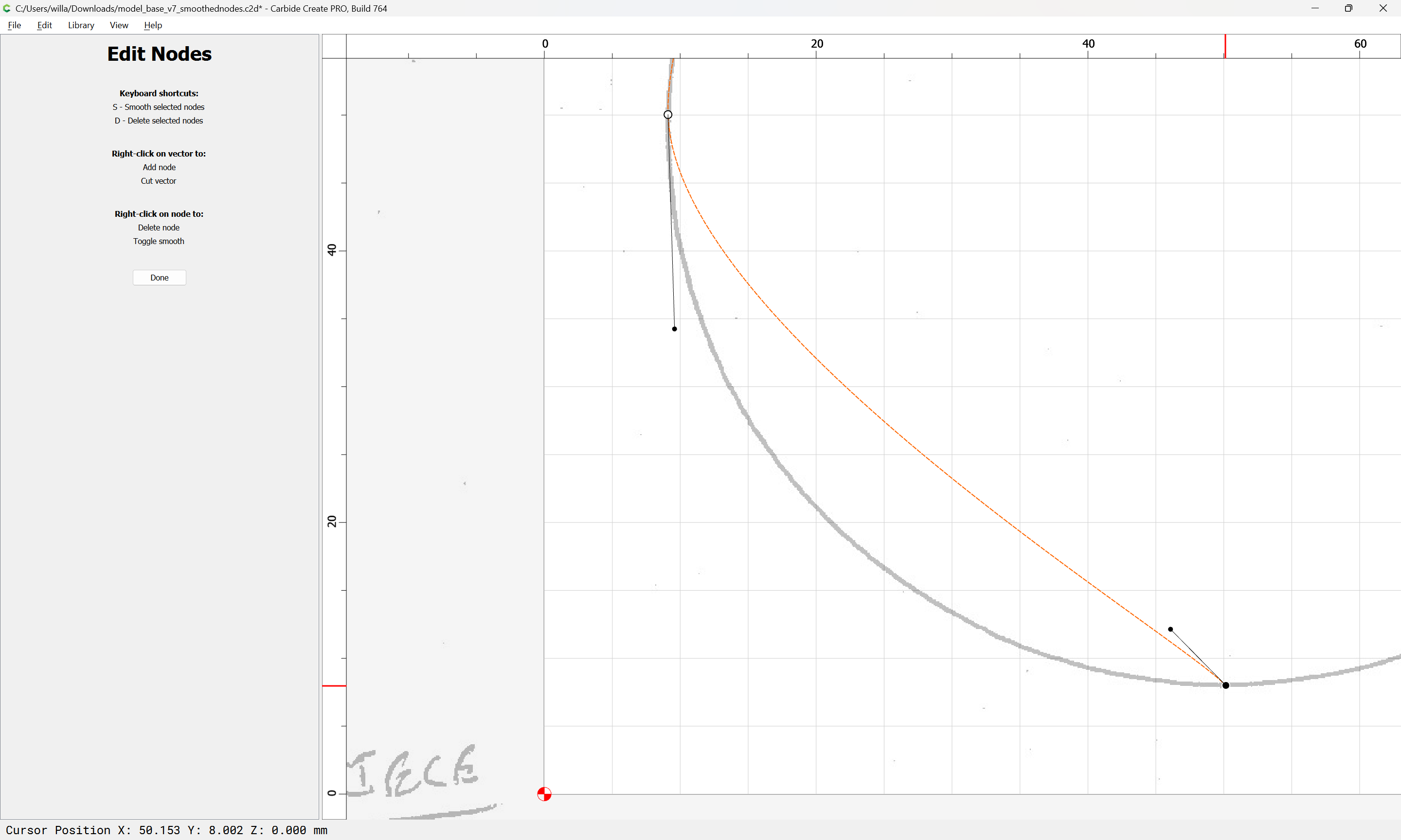
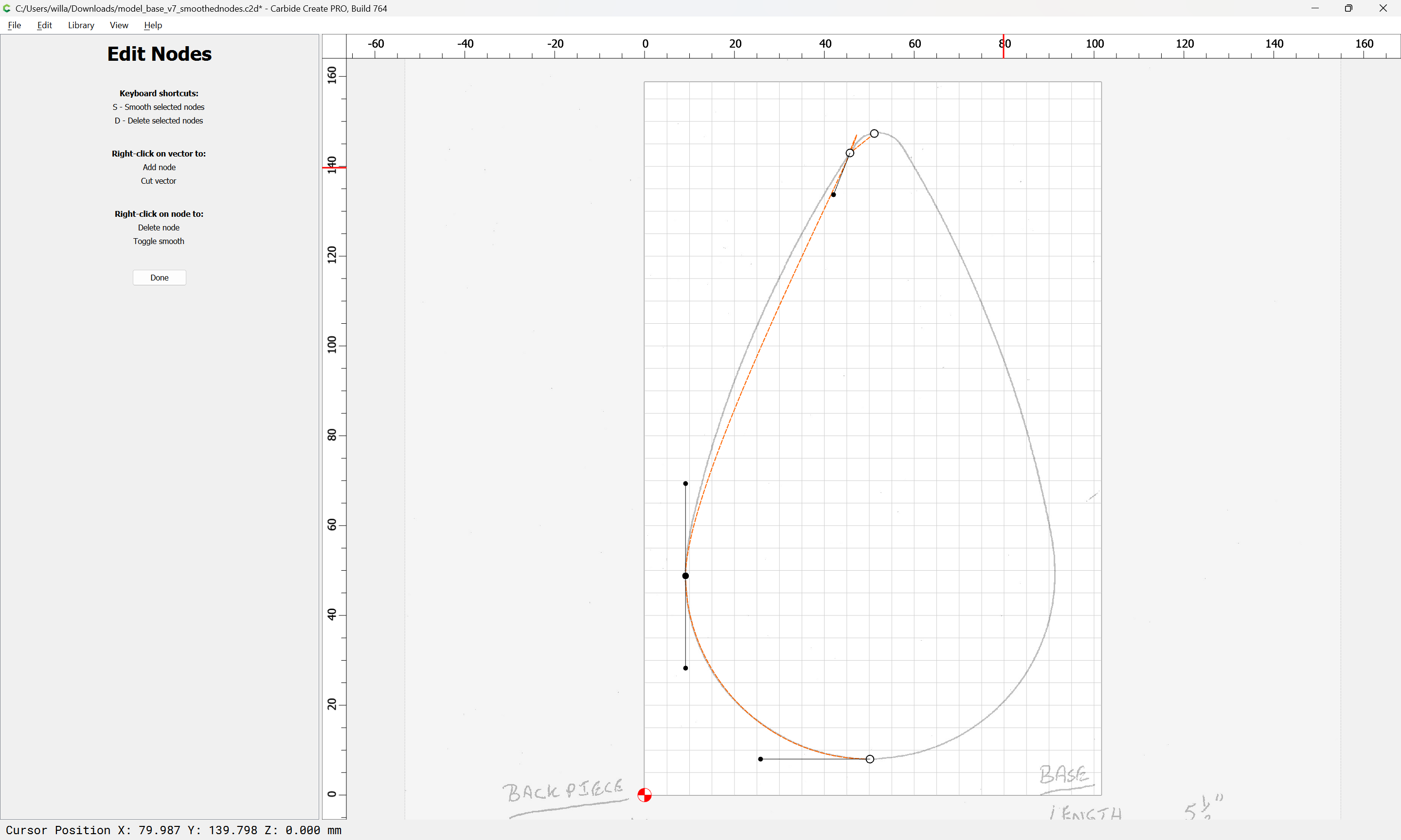
and while holding alt (option on a Mac) drag the way out-of position off-curve node so that it reshapes the upper portion of the curve, but doesn’t move the associated off-curve node for the lower portion which is already in position:
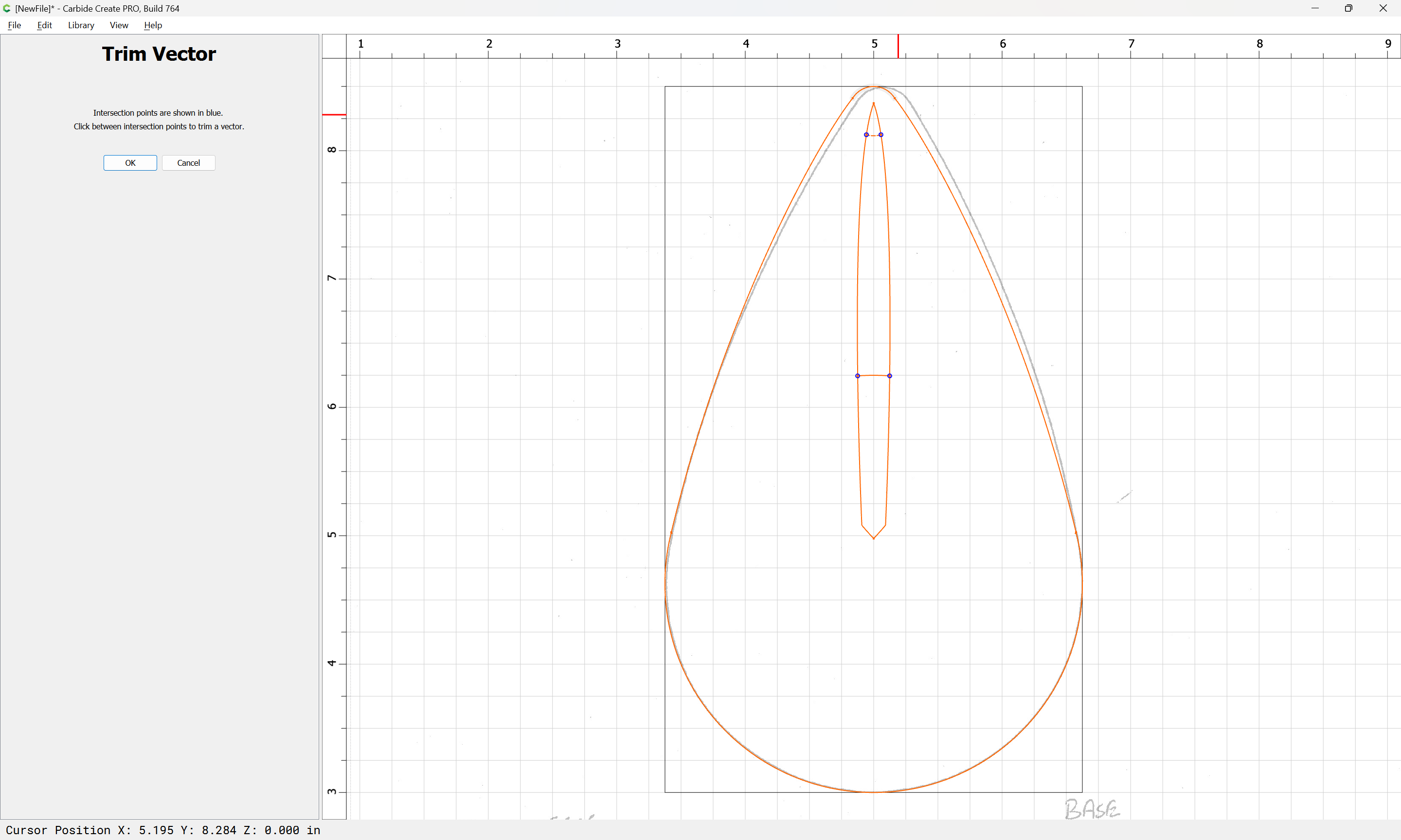
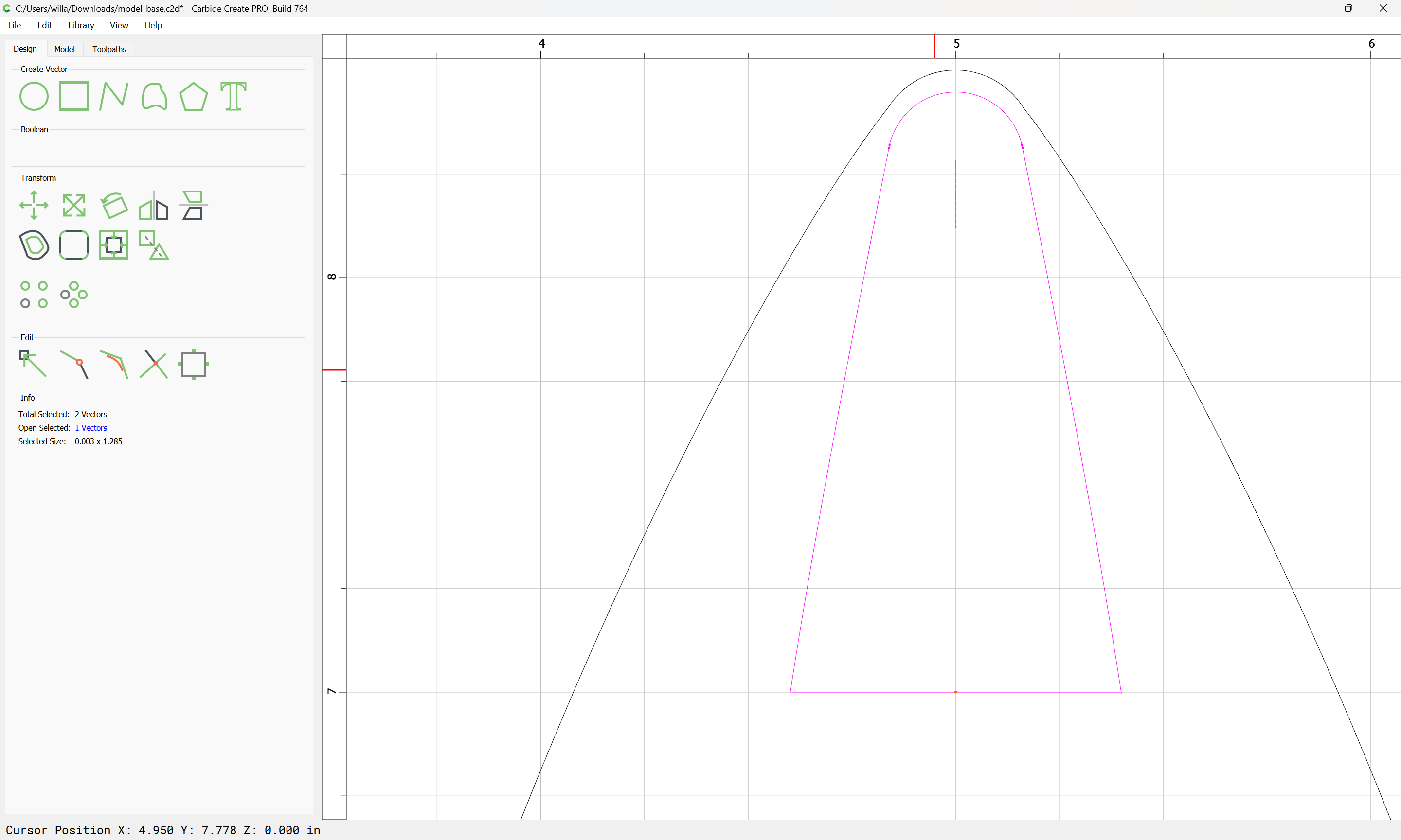
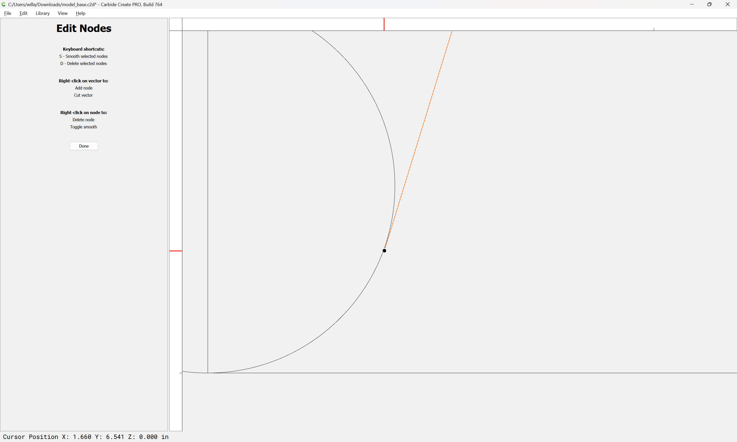
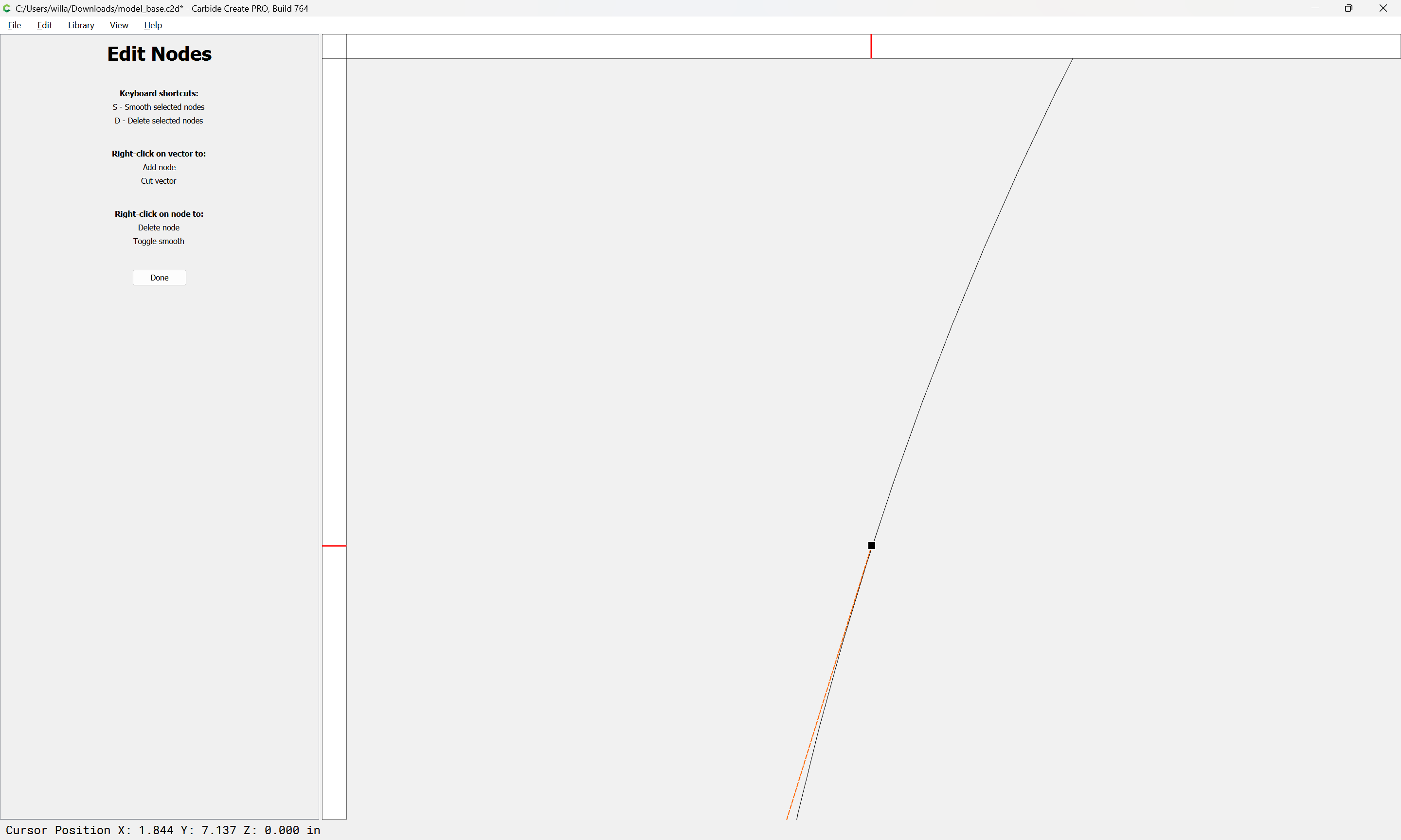
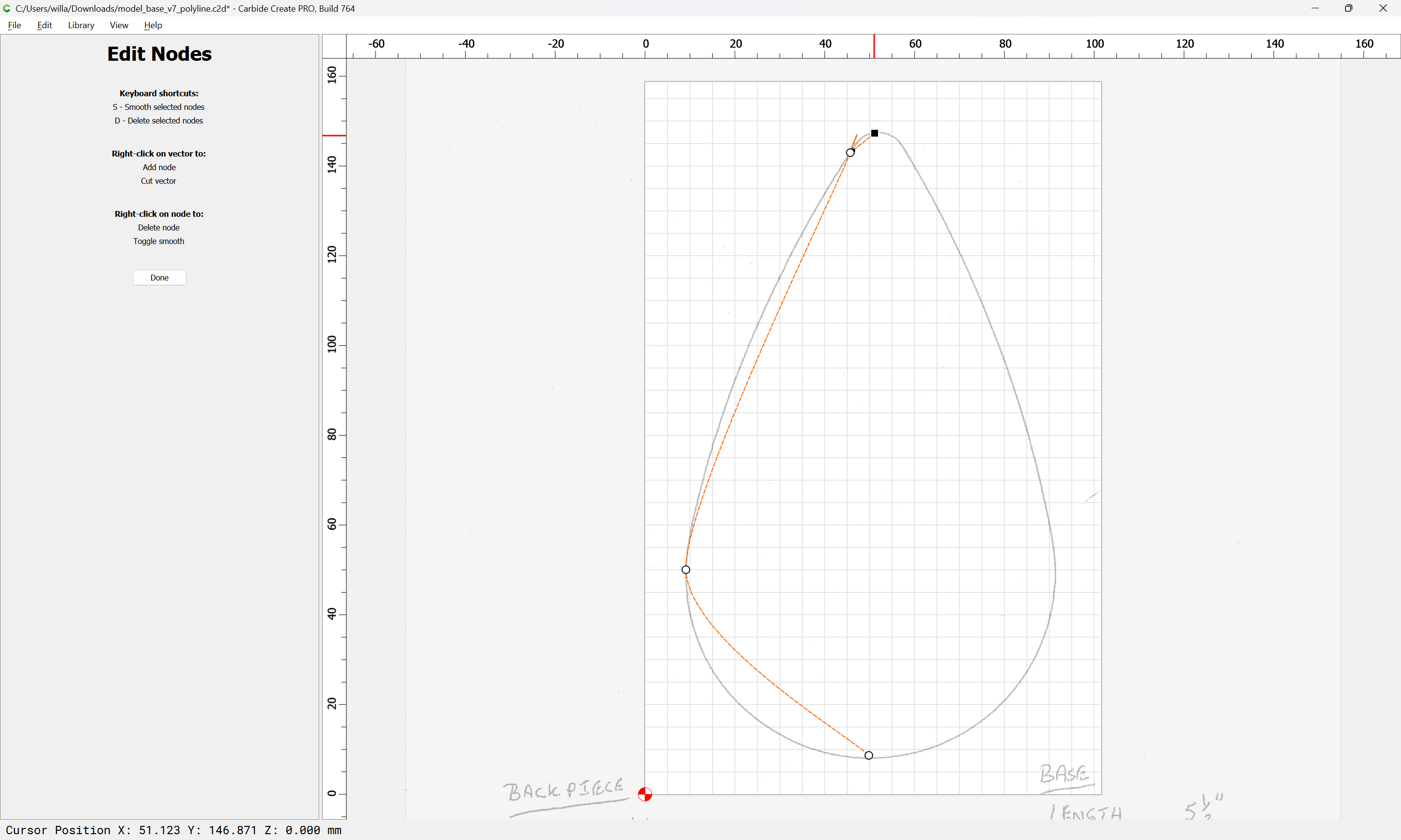
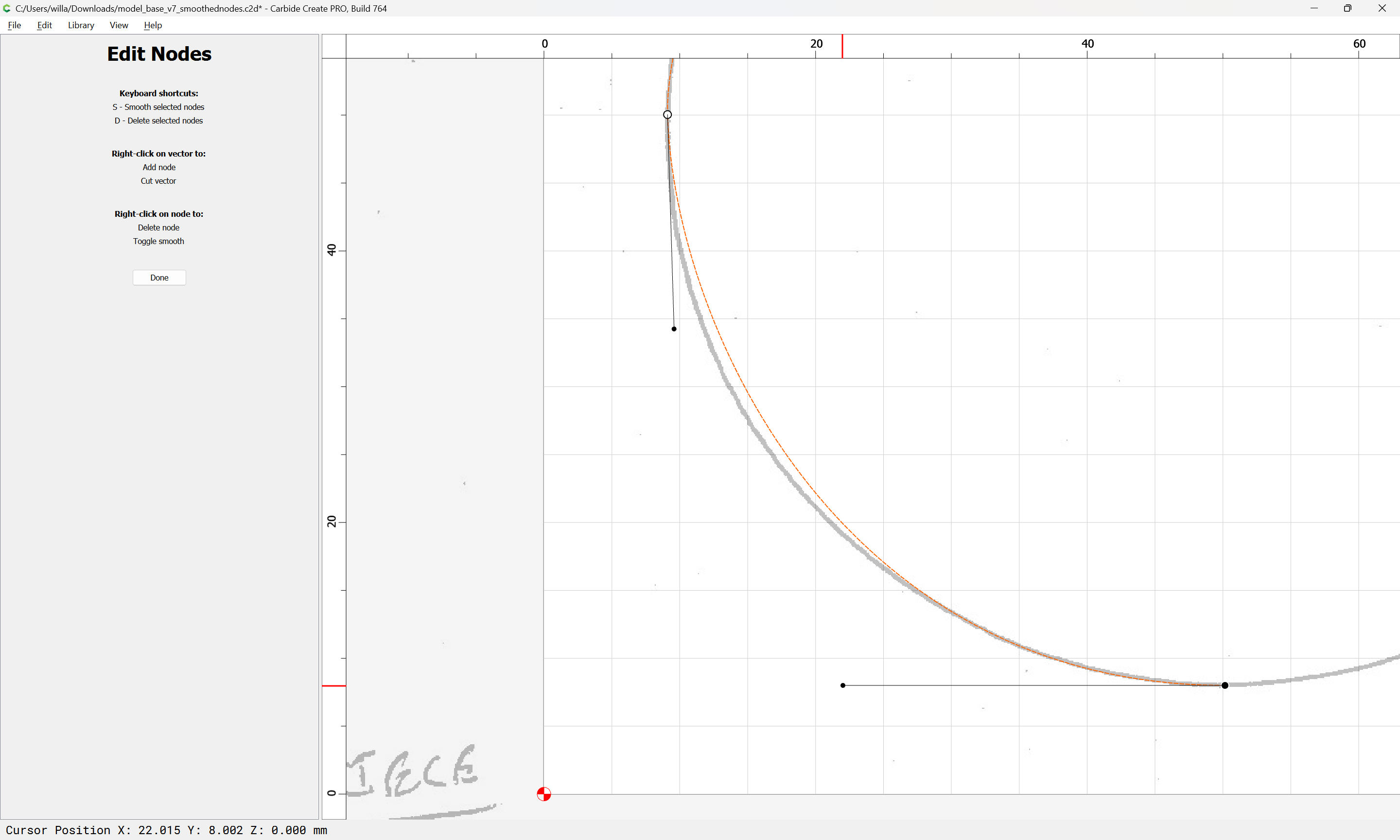
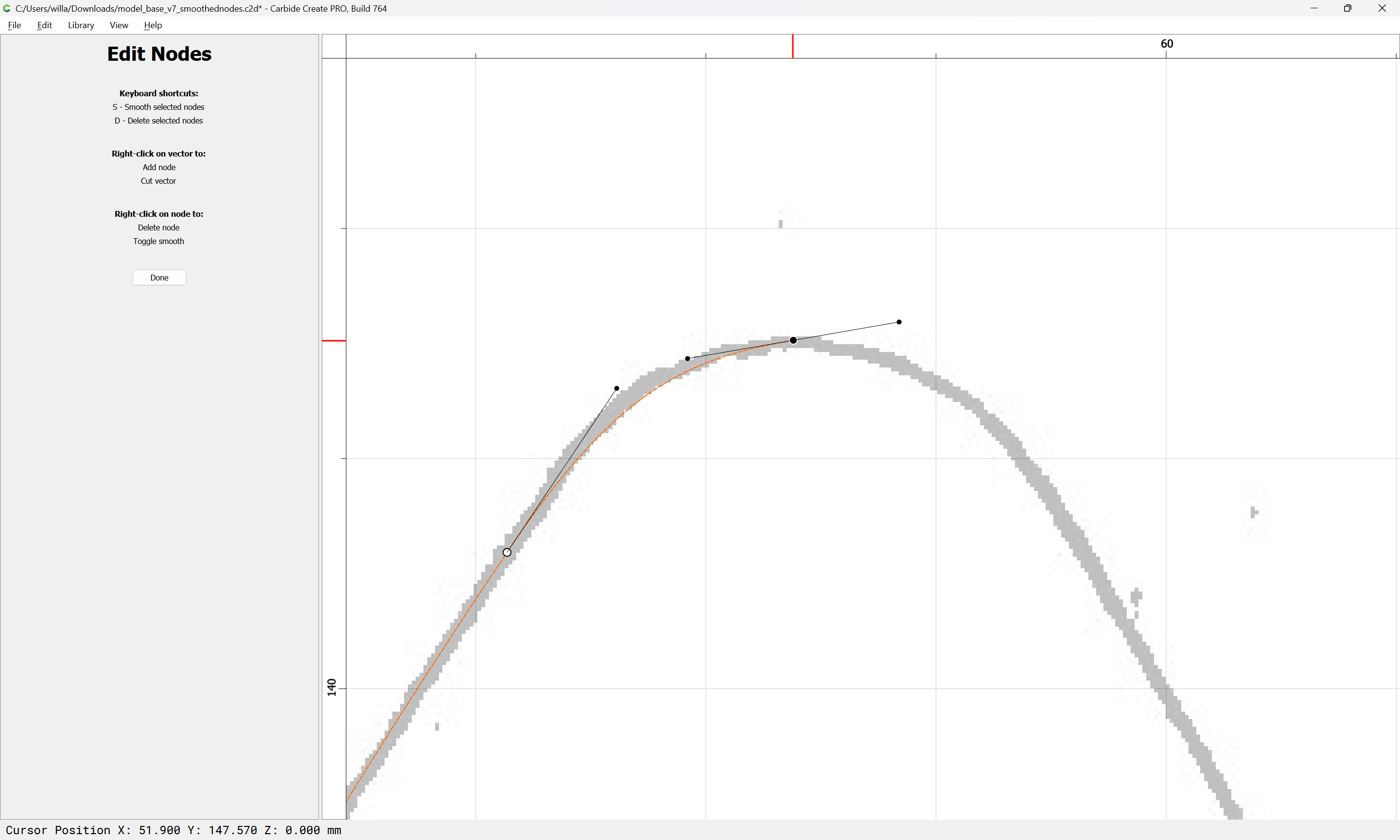
adjust the remaining off-curve node:
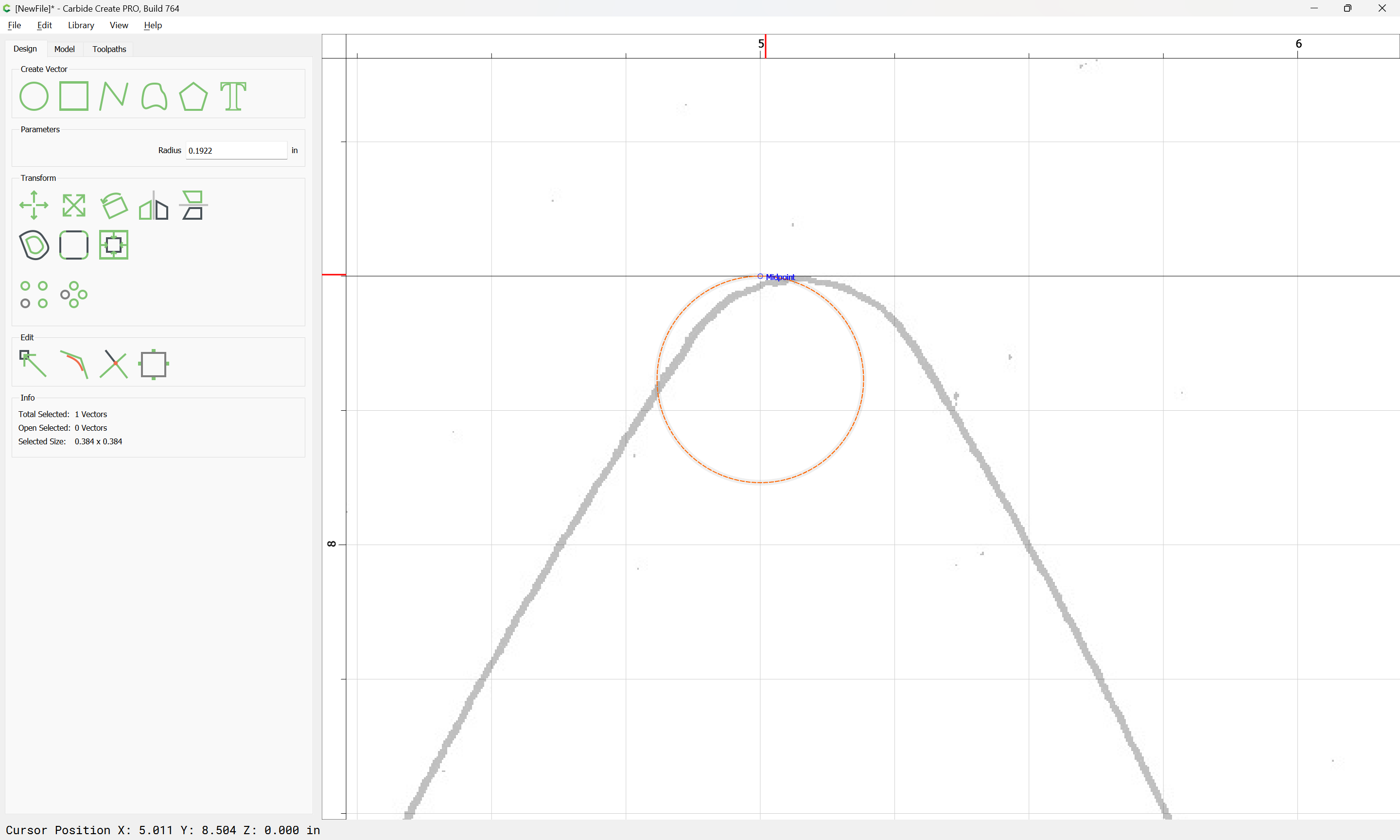
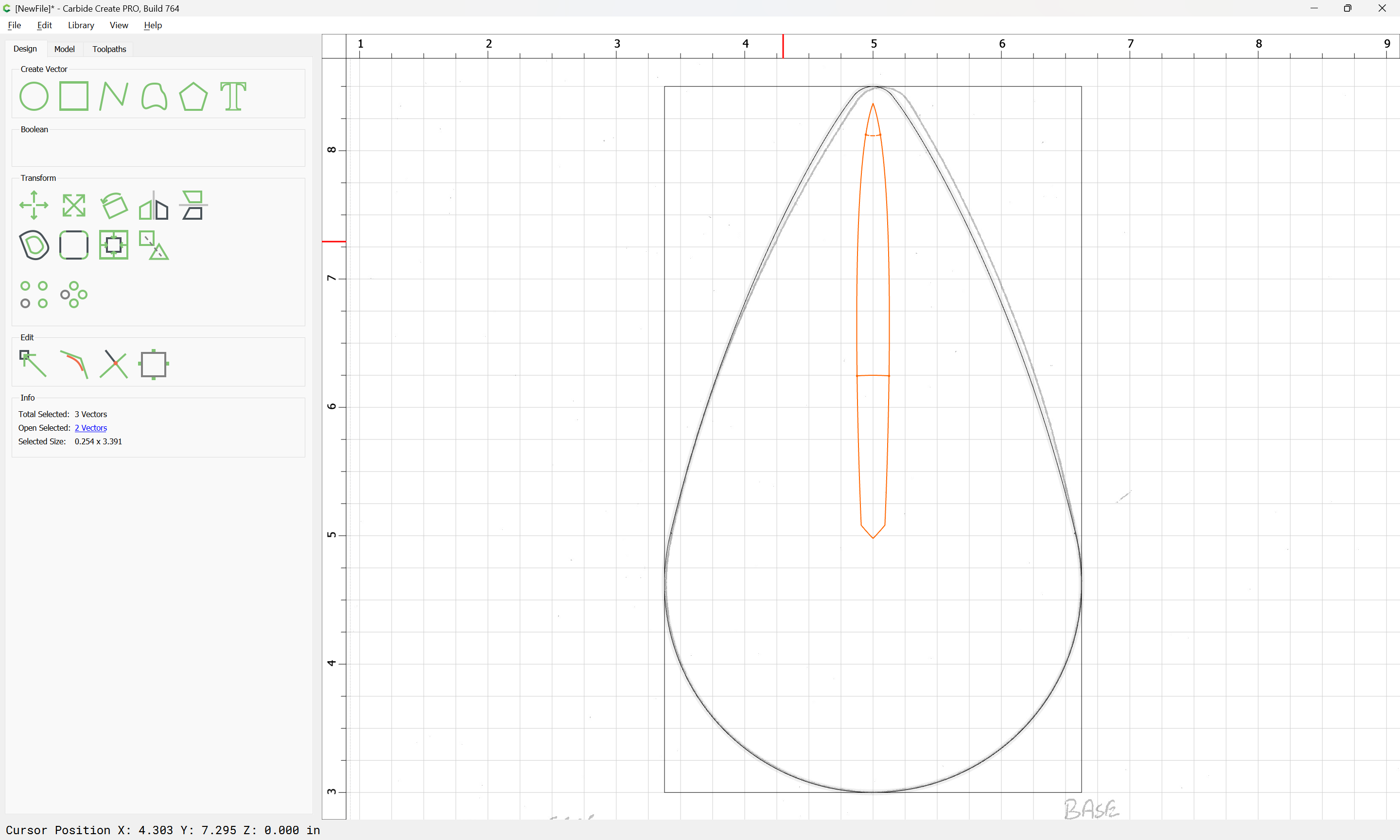
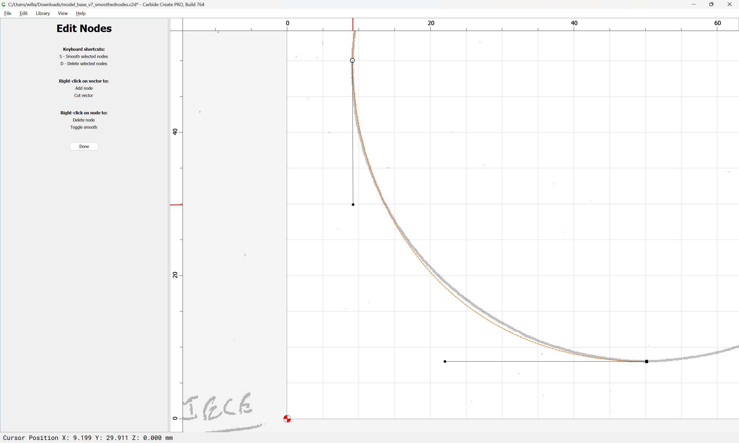
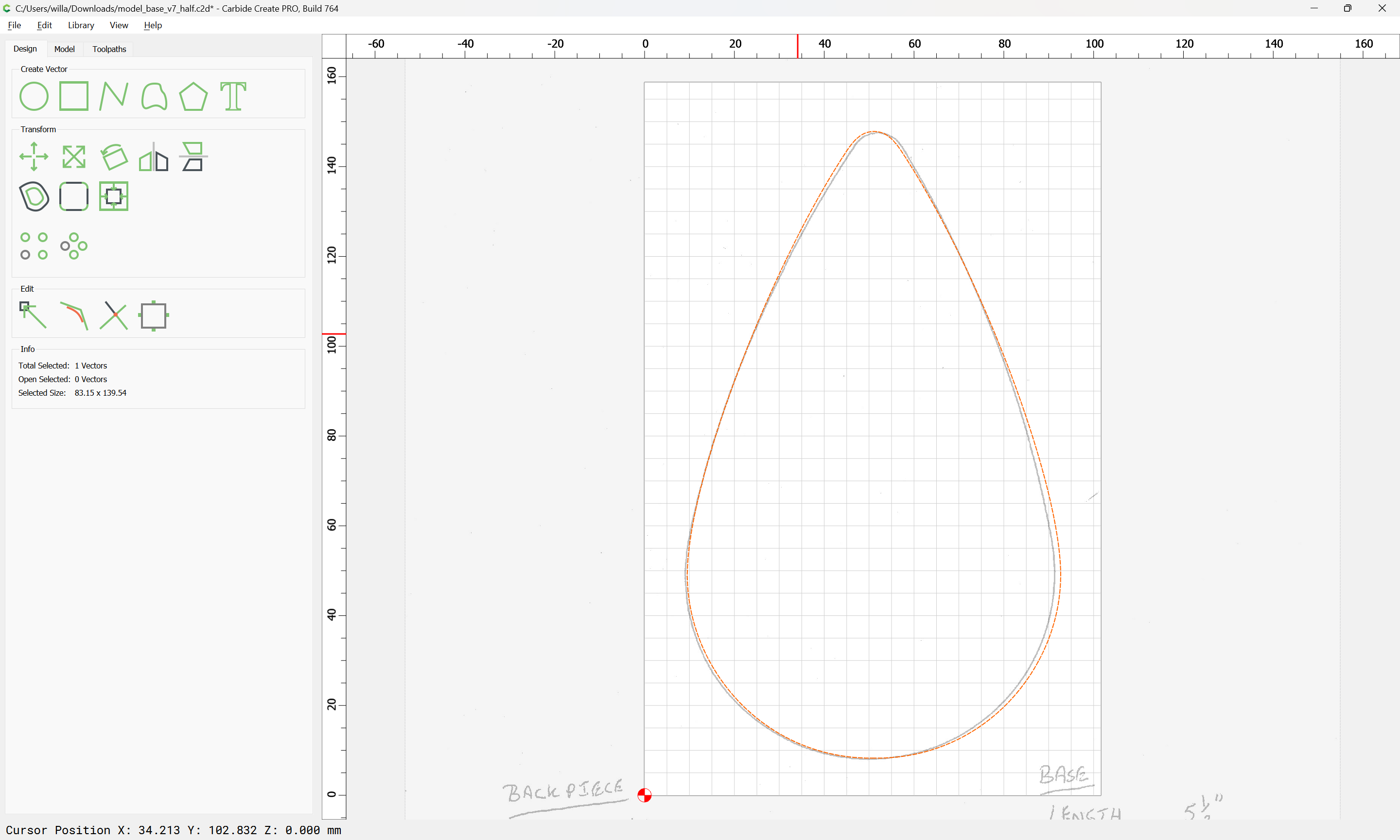
and adjust the position of the on-curve node so that it is at the apex:
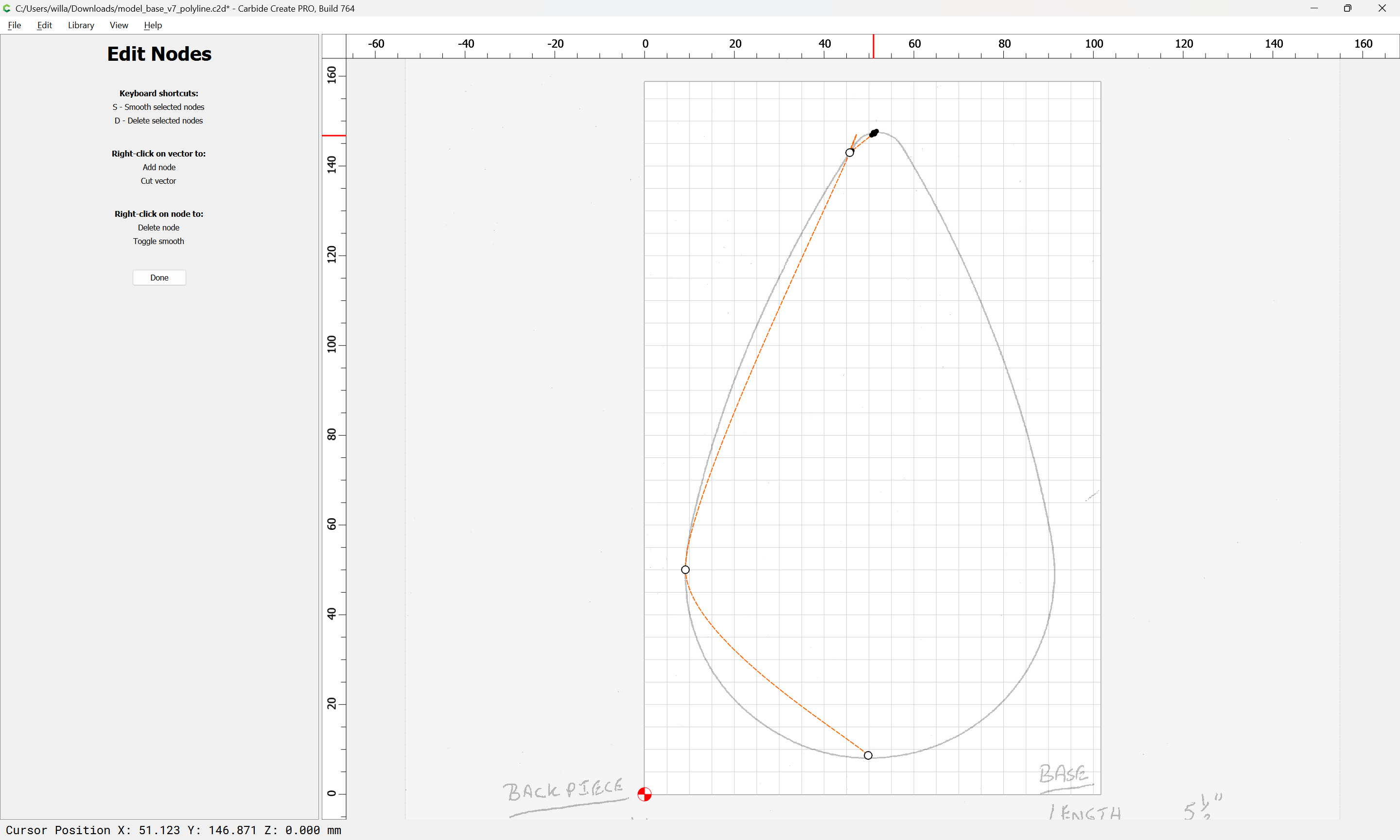
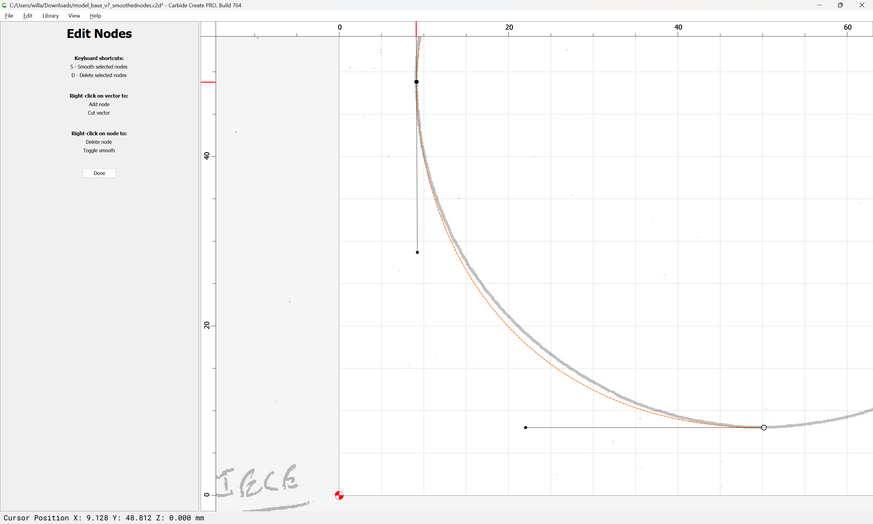
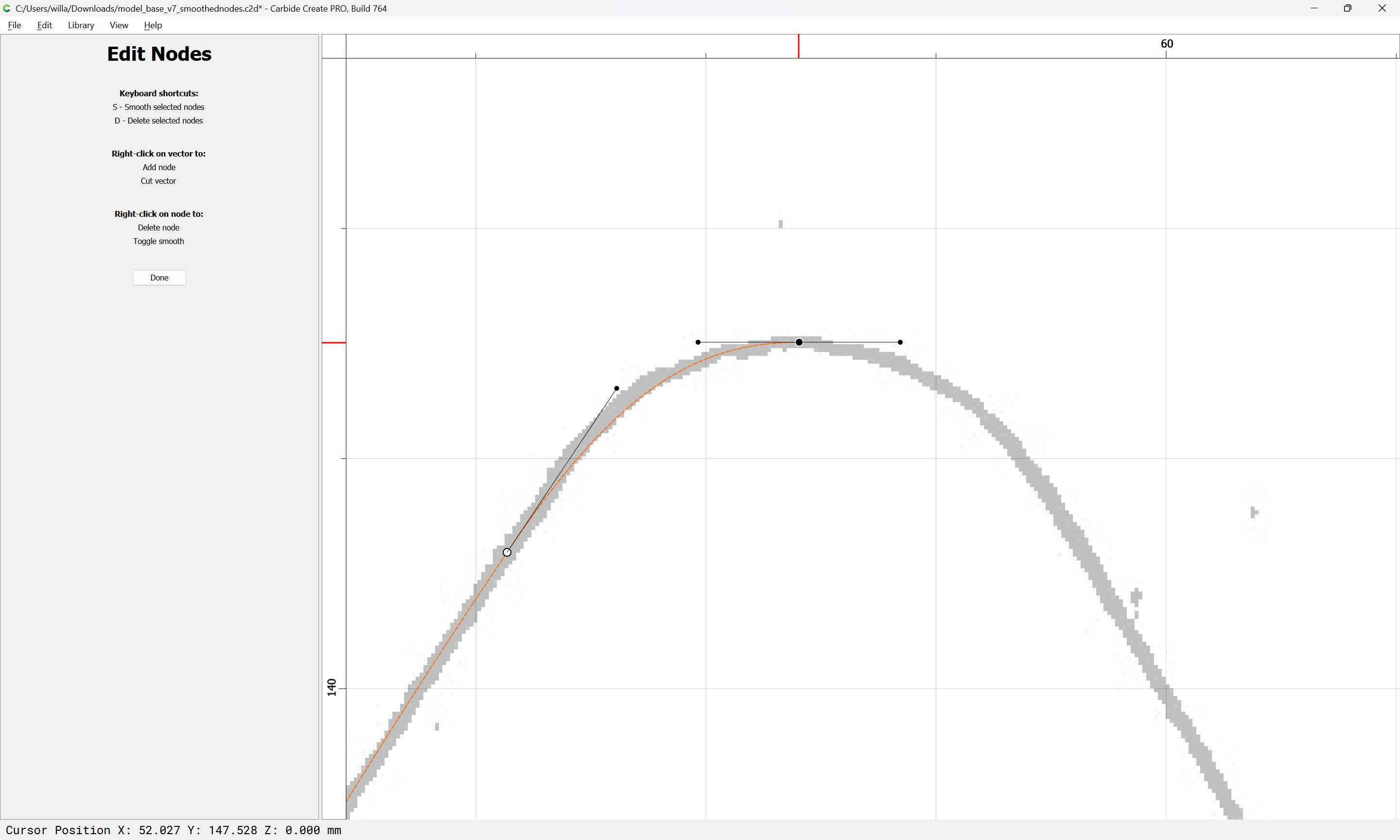
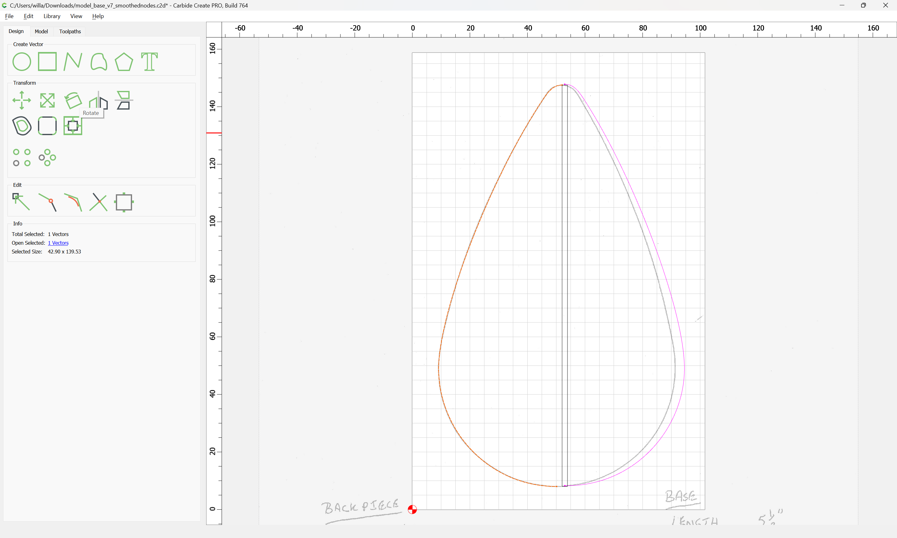
and adjust the off-curve node so that it is level so that when joined, the curve will be smooth, not pointed:
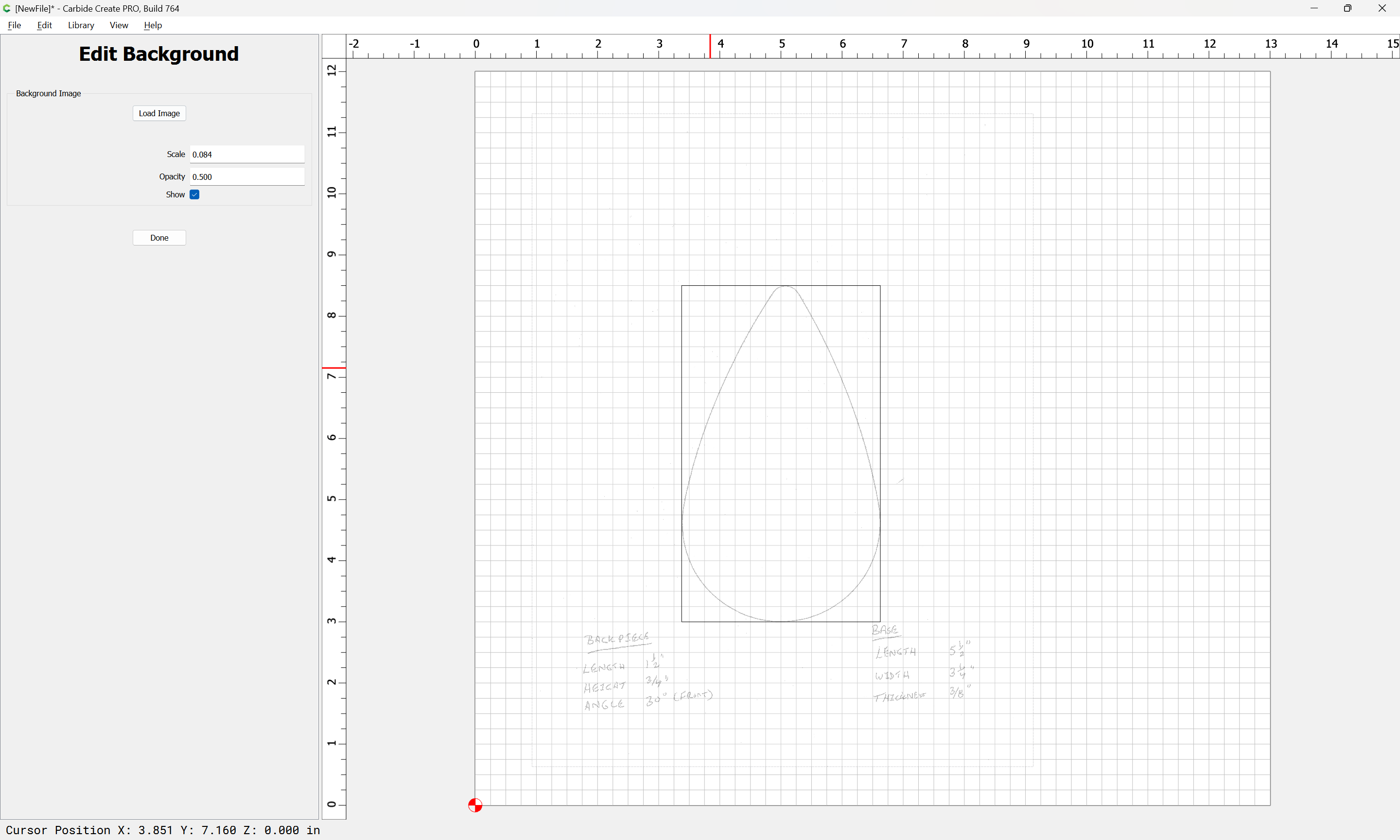
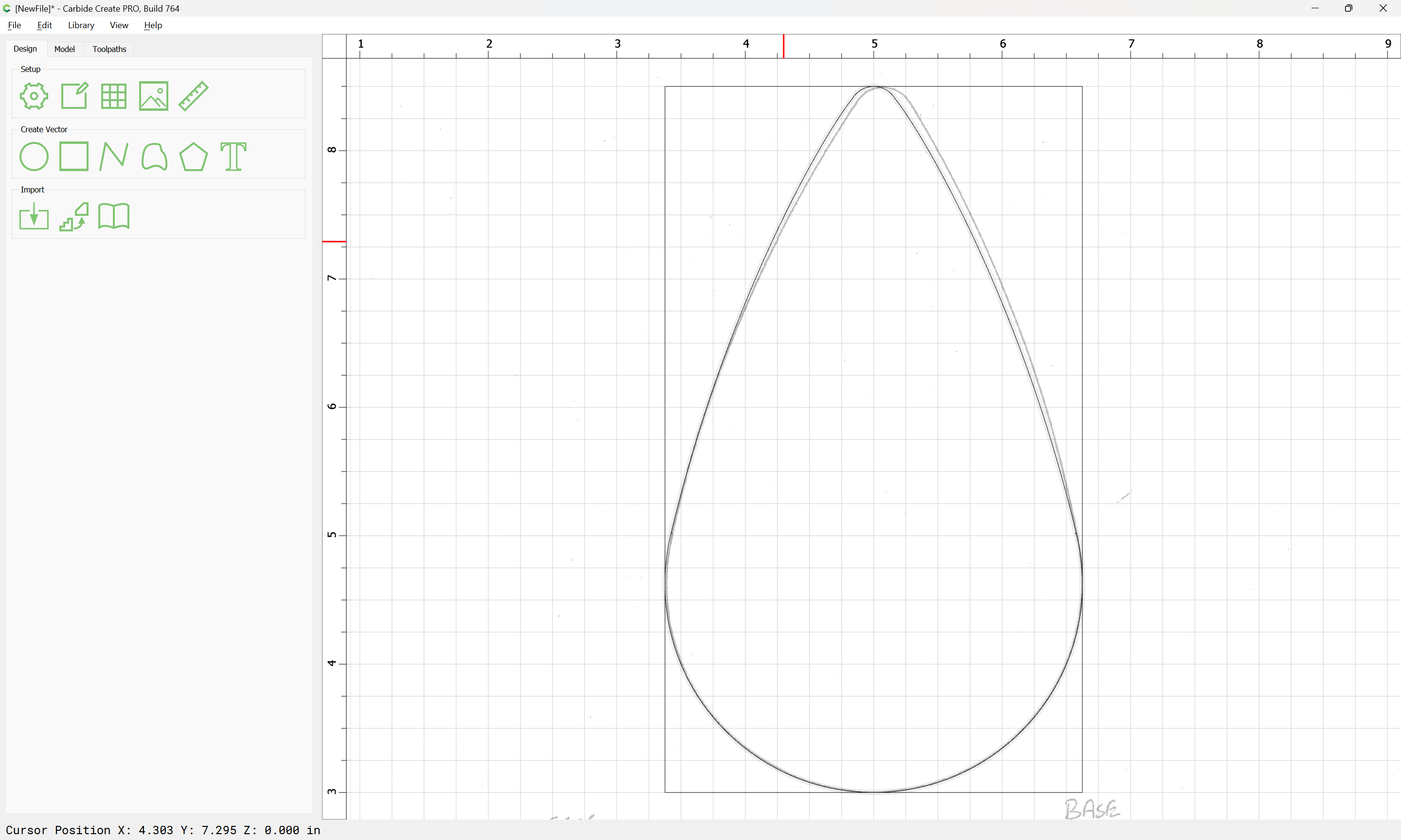
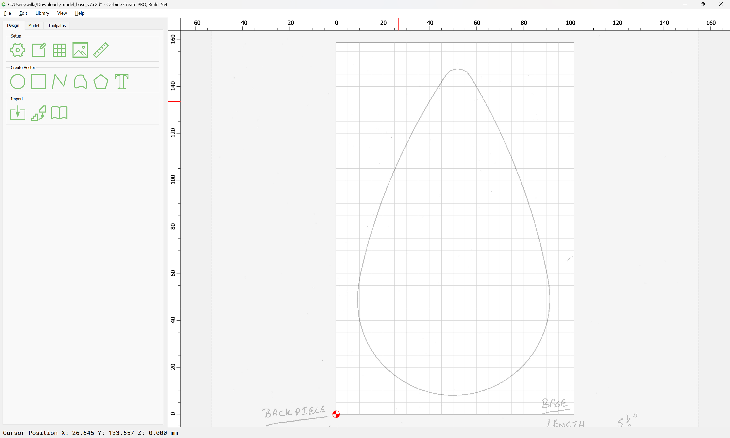
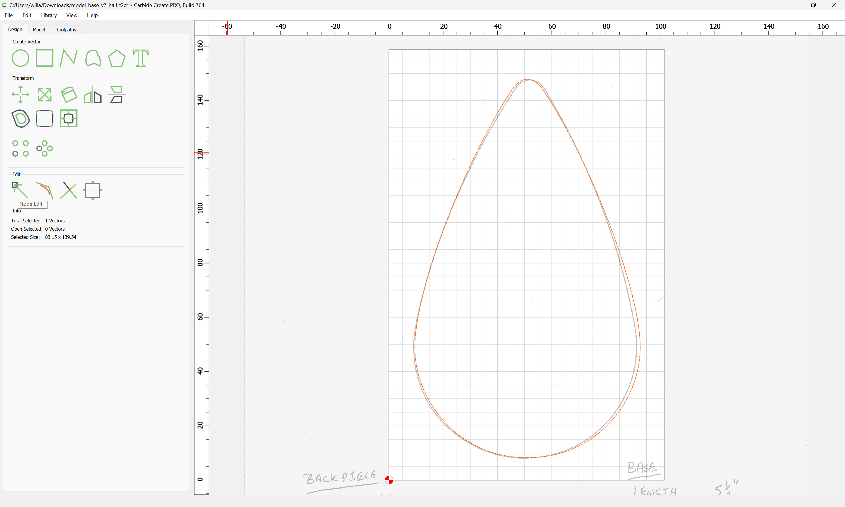
Done
model_base_v7_half.c2d (236 KB)
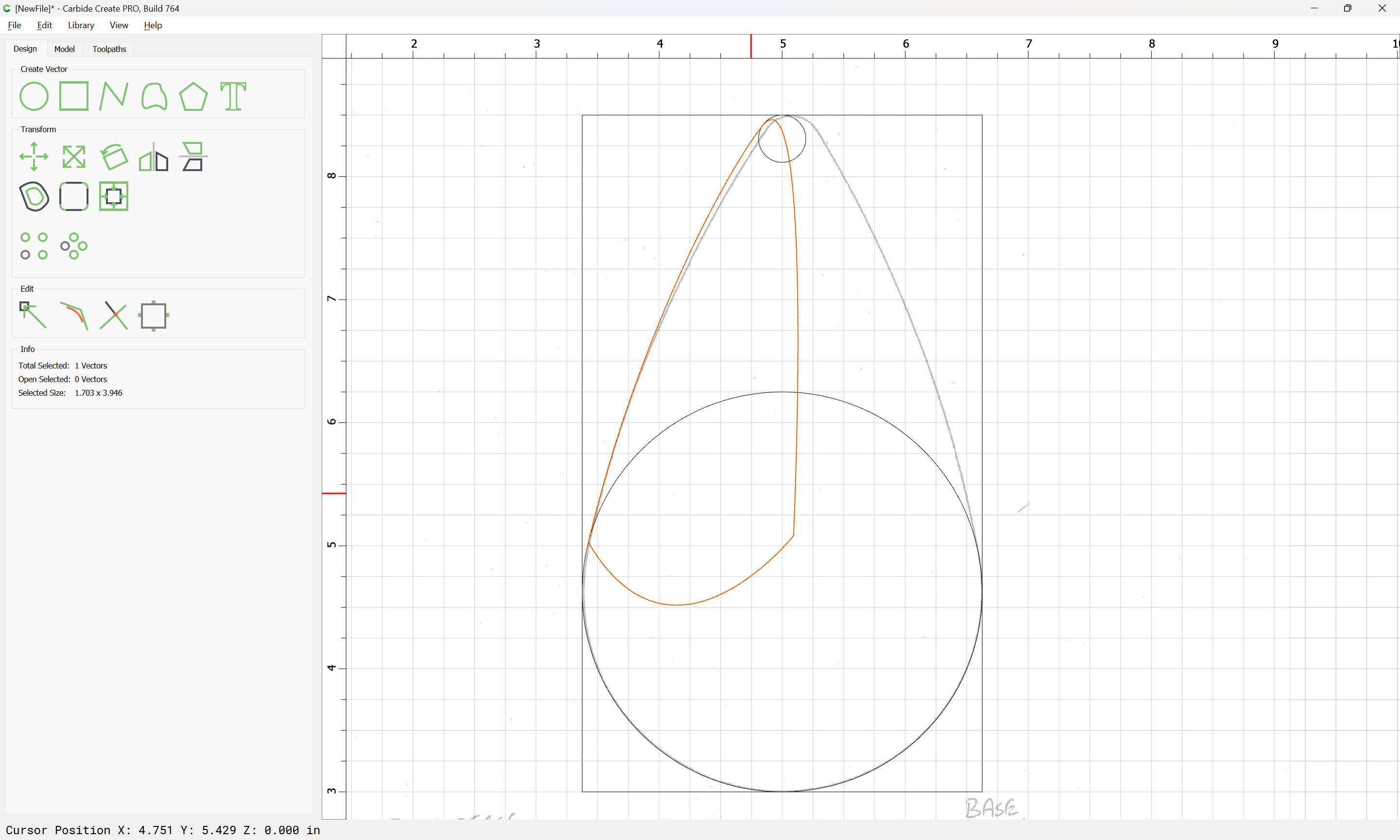
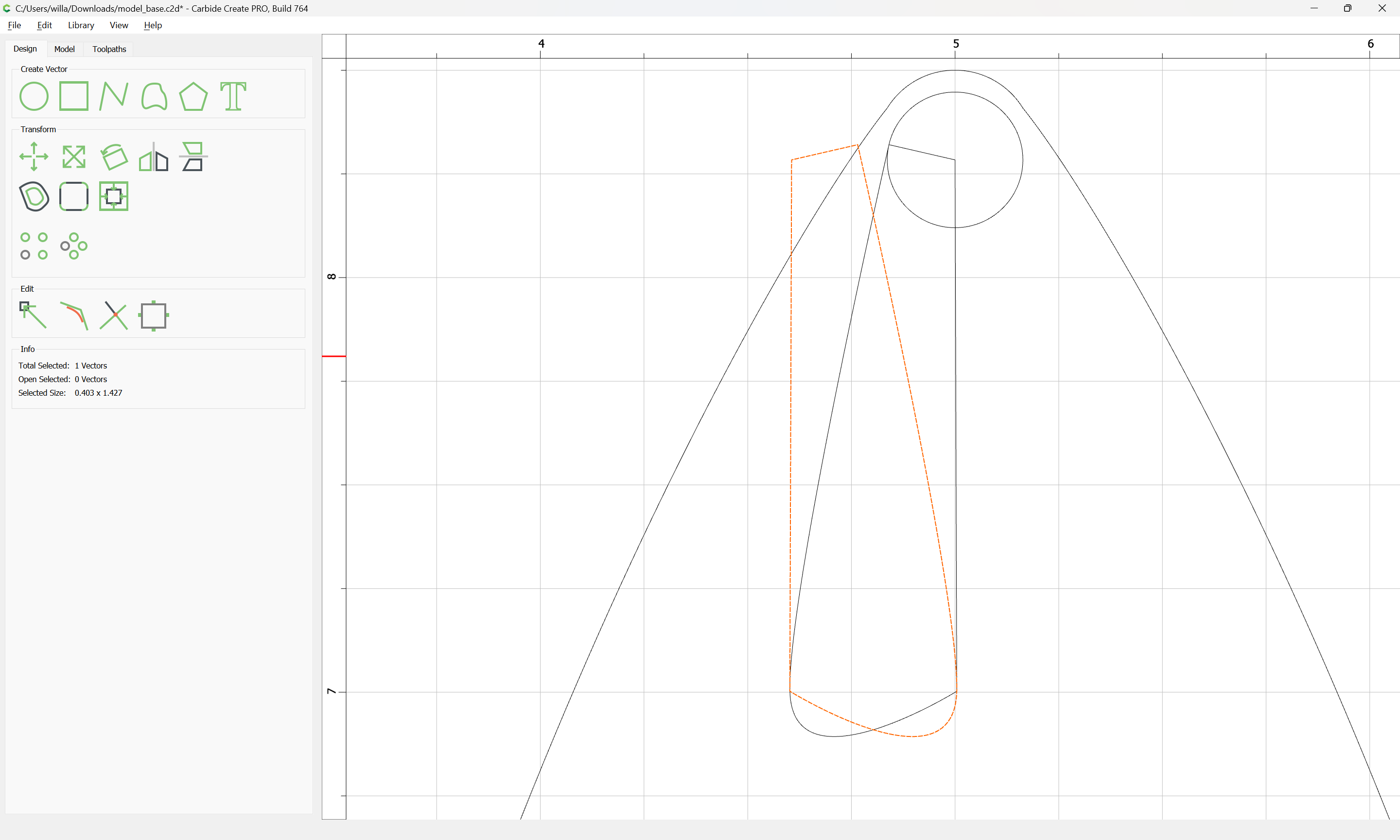
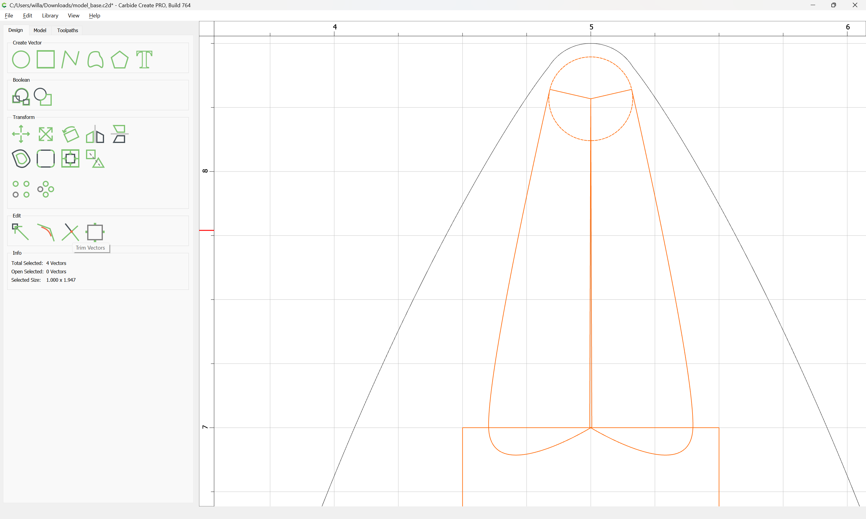
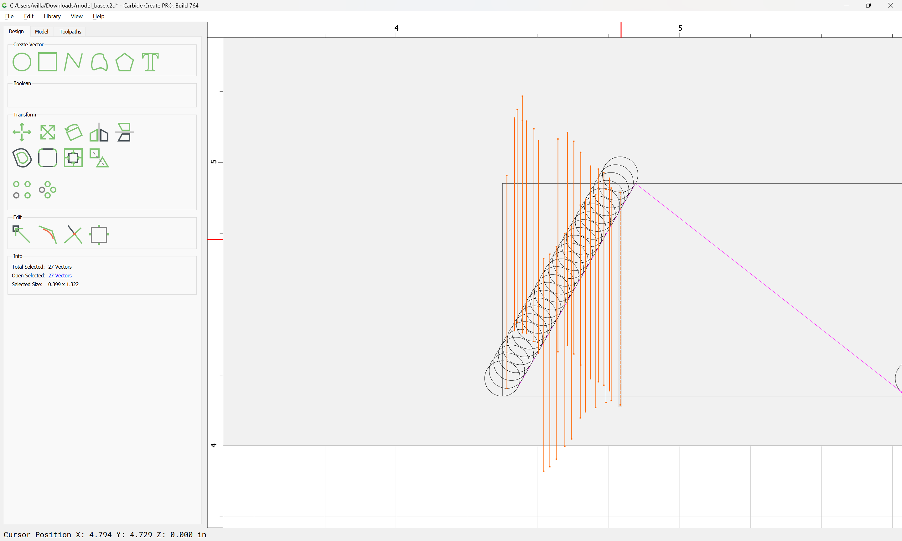
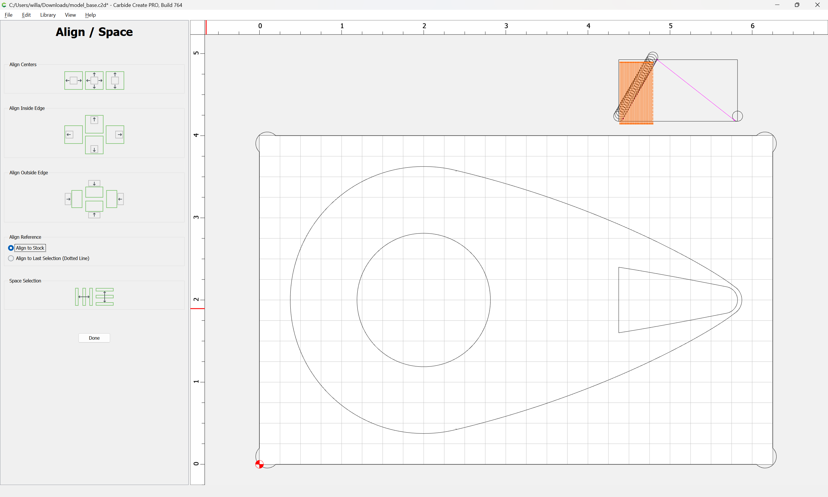
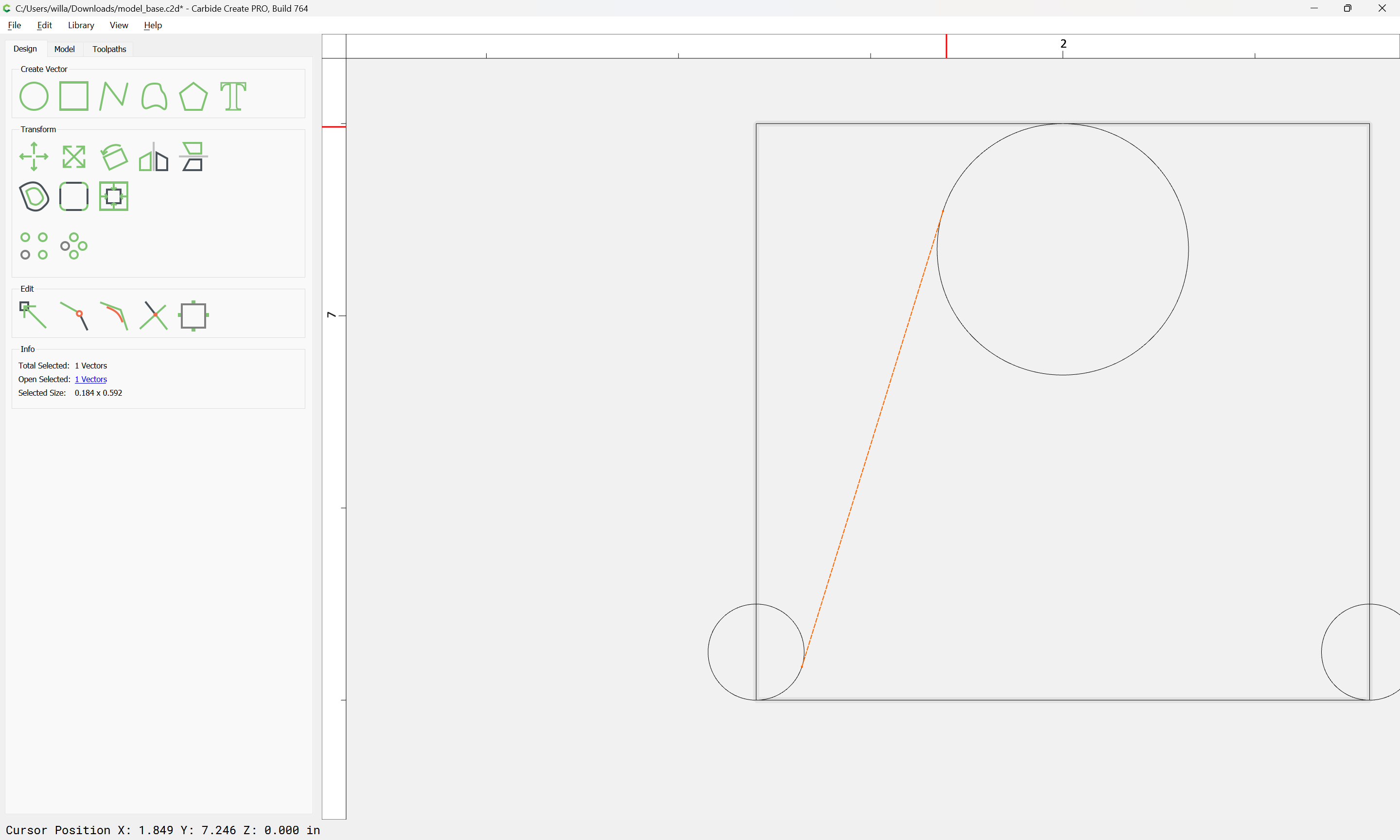
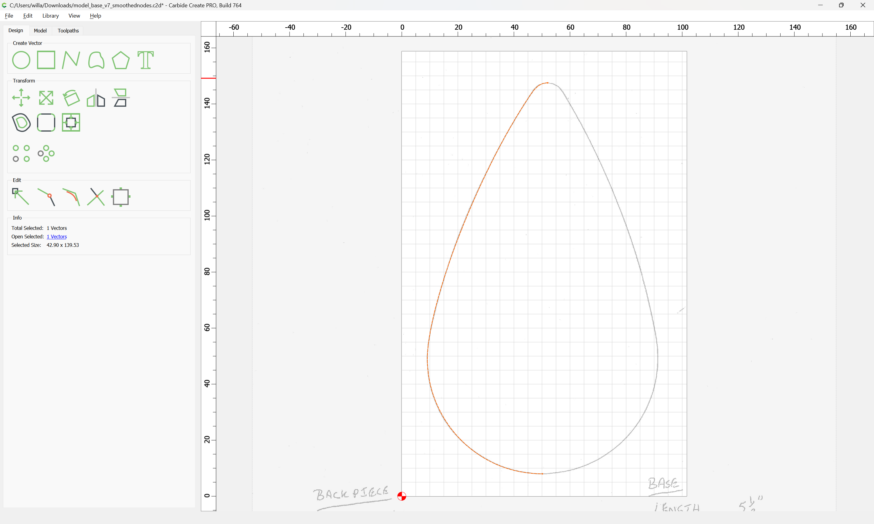
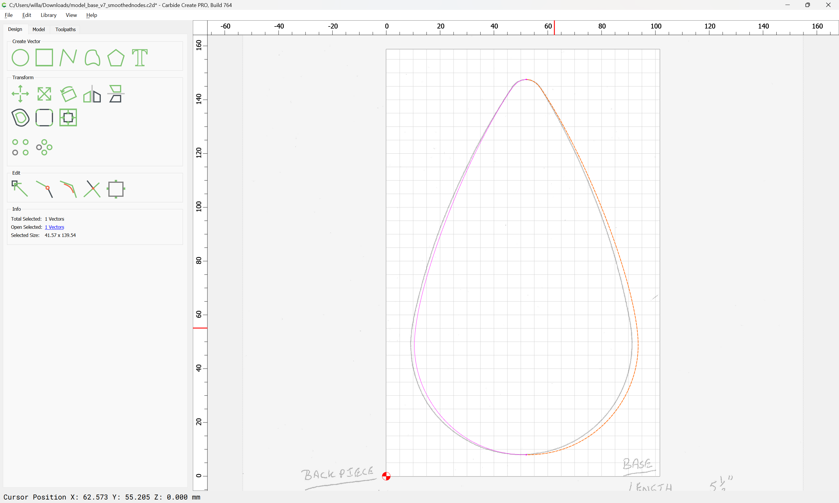
copy-paste the left half:
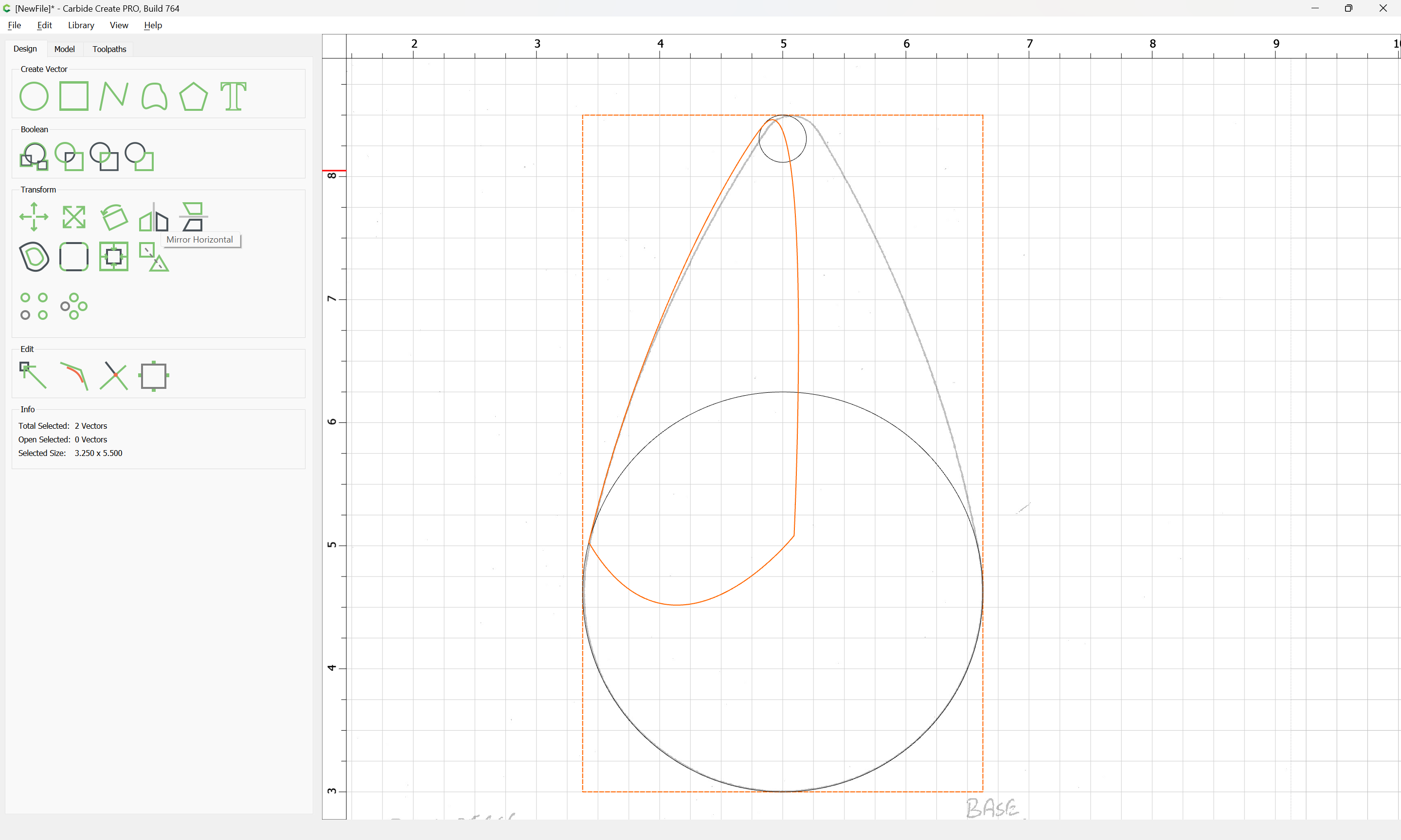
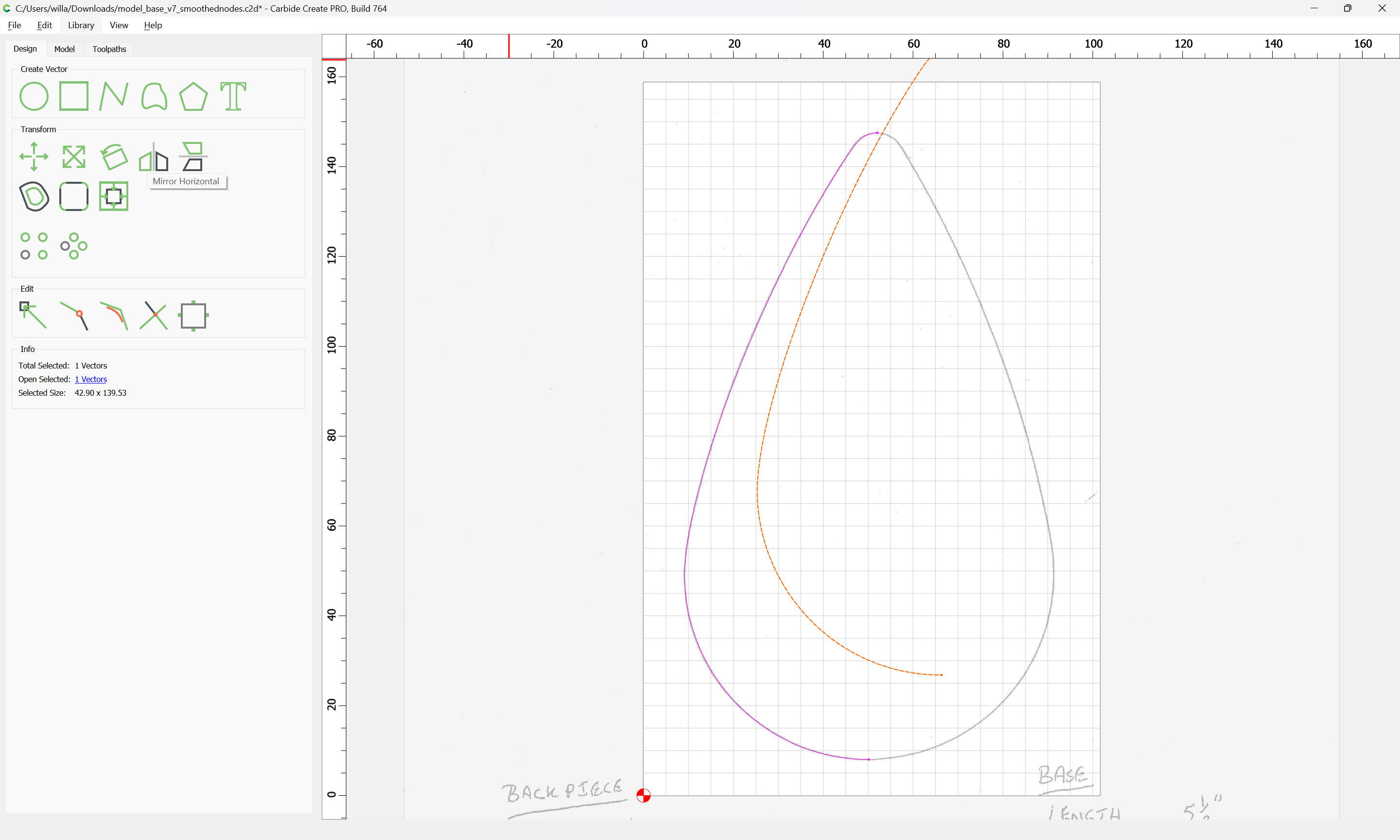
Mirror it horizontally:
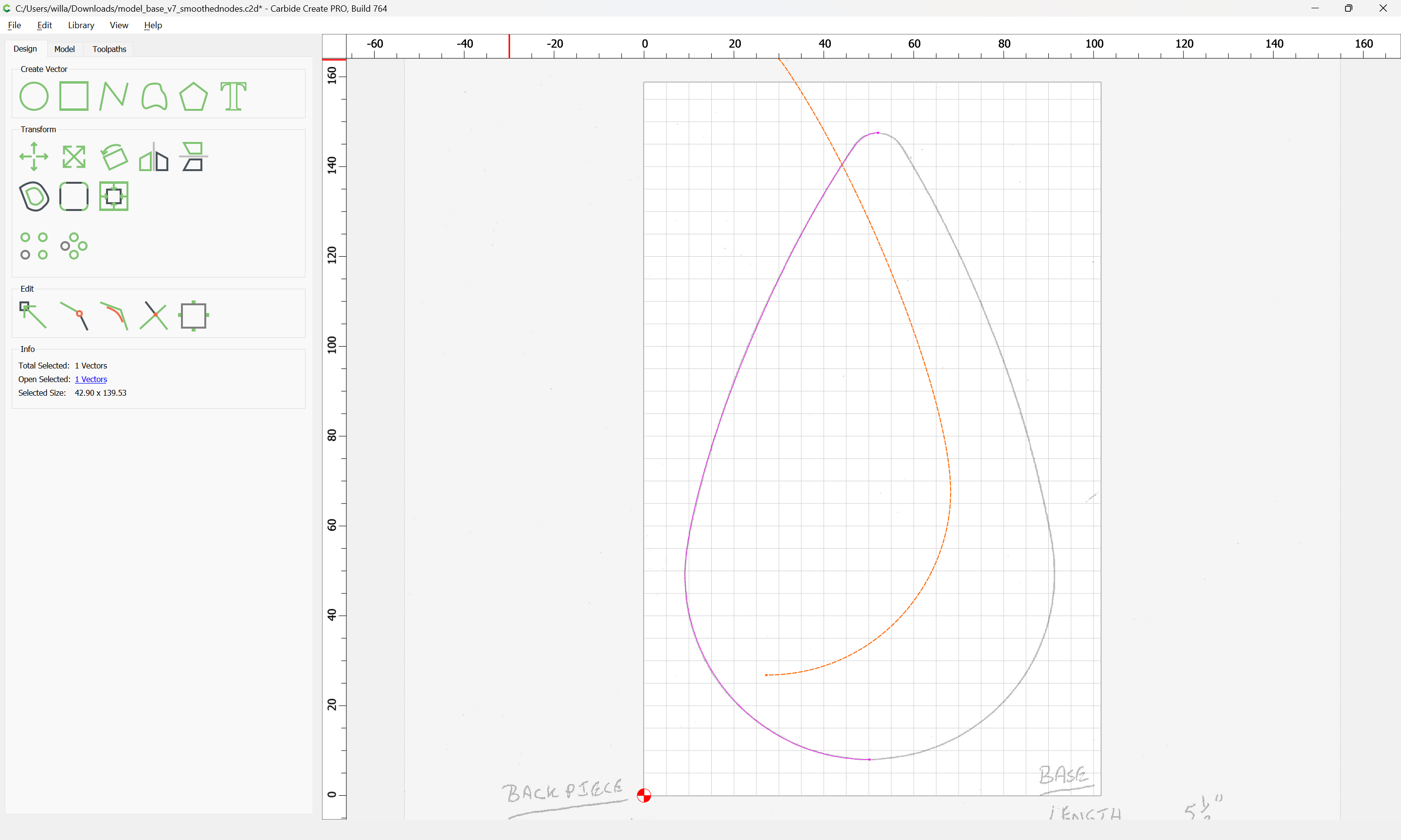
and drag it into registration with the other half:
where we see that things don’t quite line up.
(I believe because the scan was a bit askew)
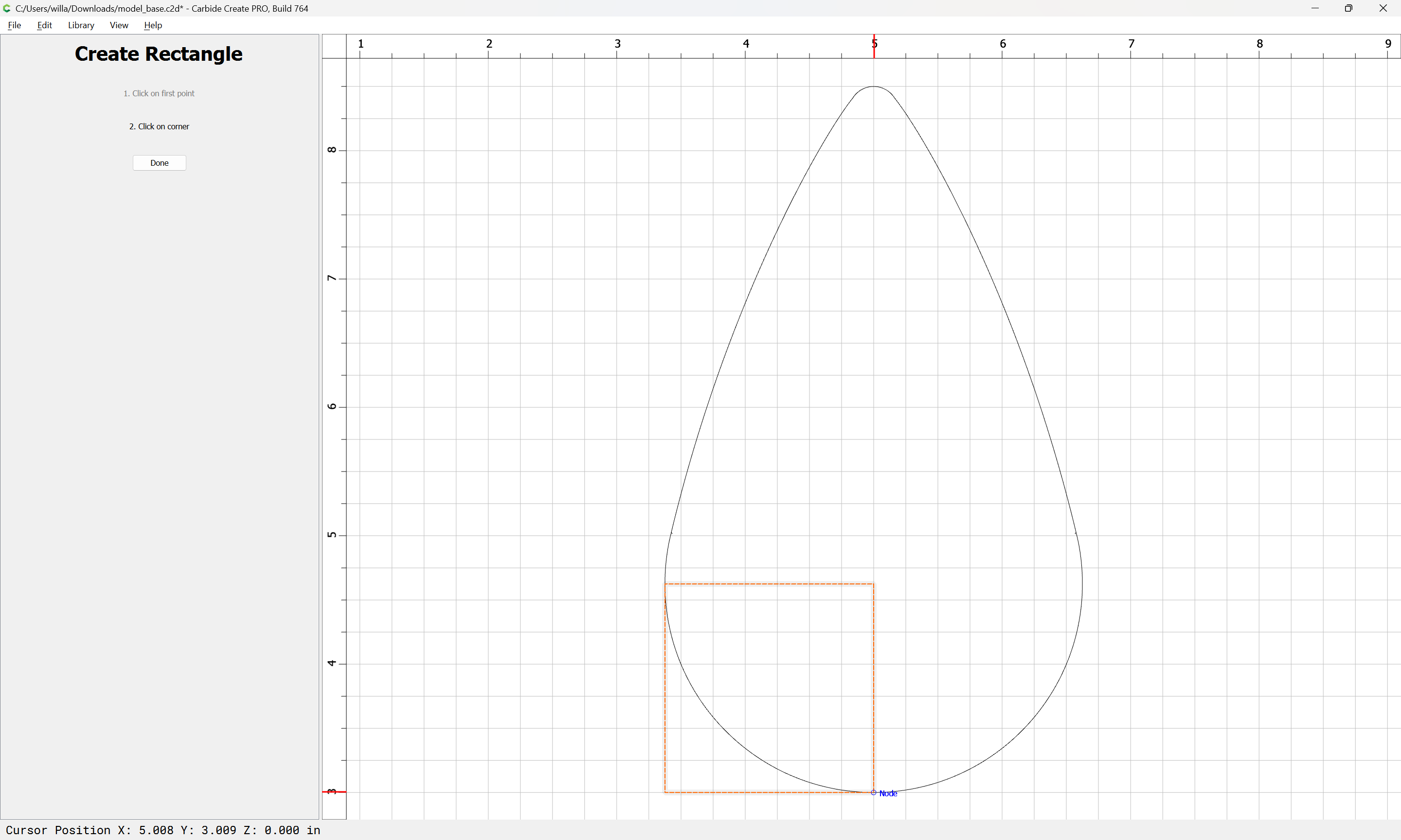
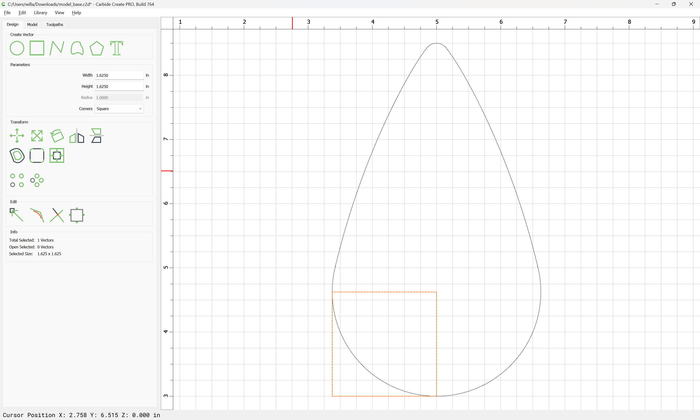
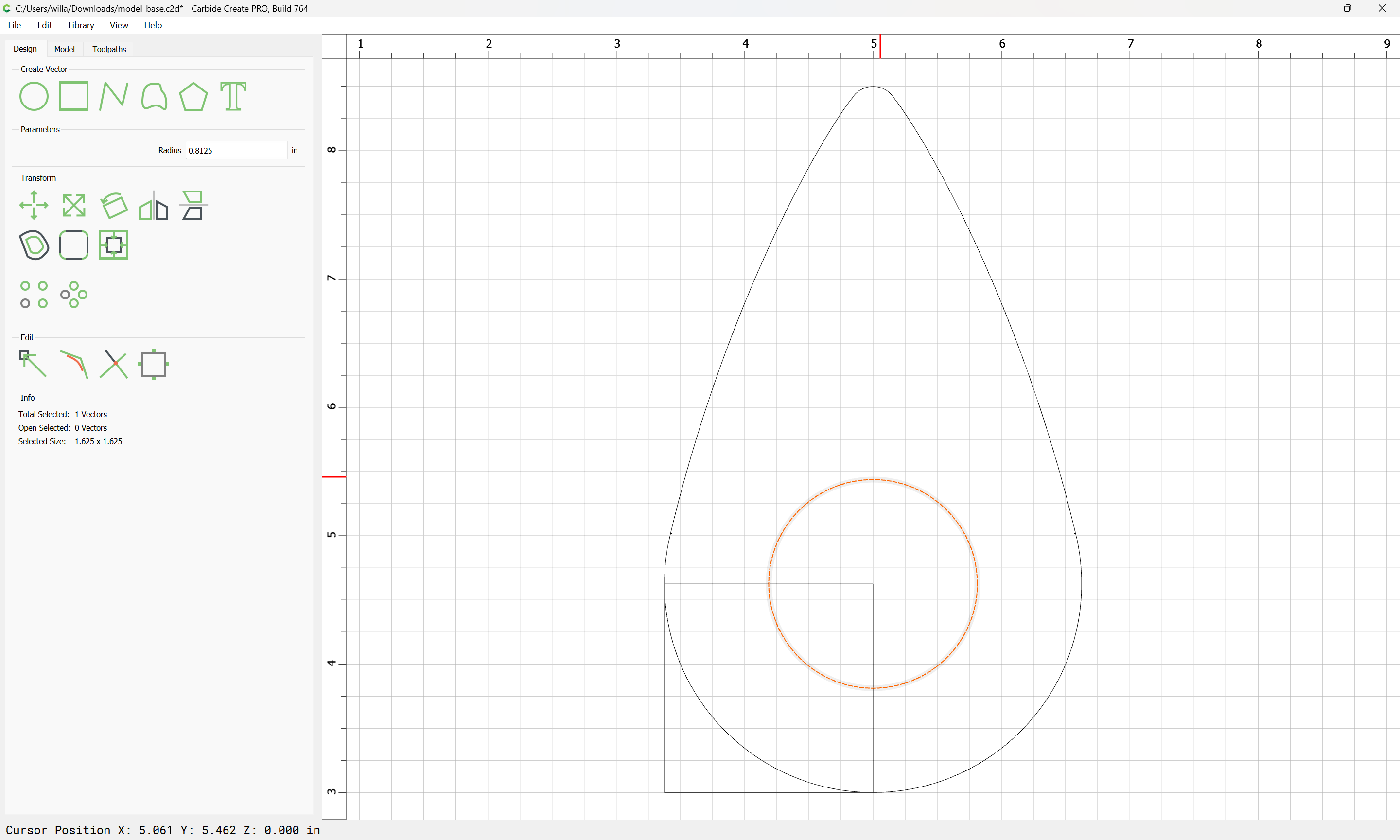
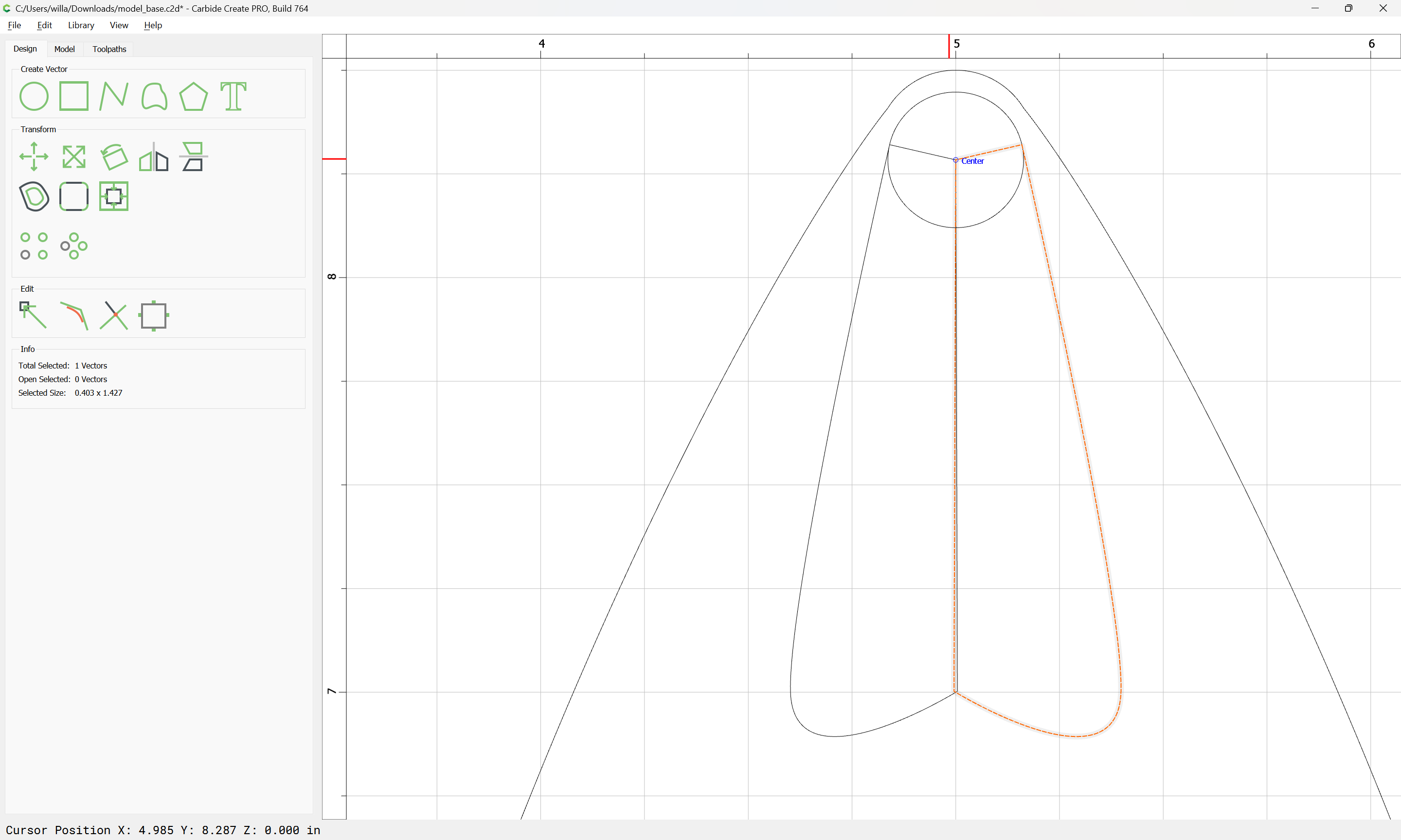
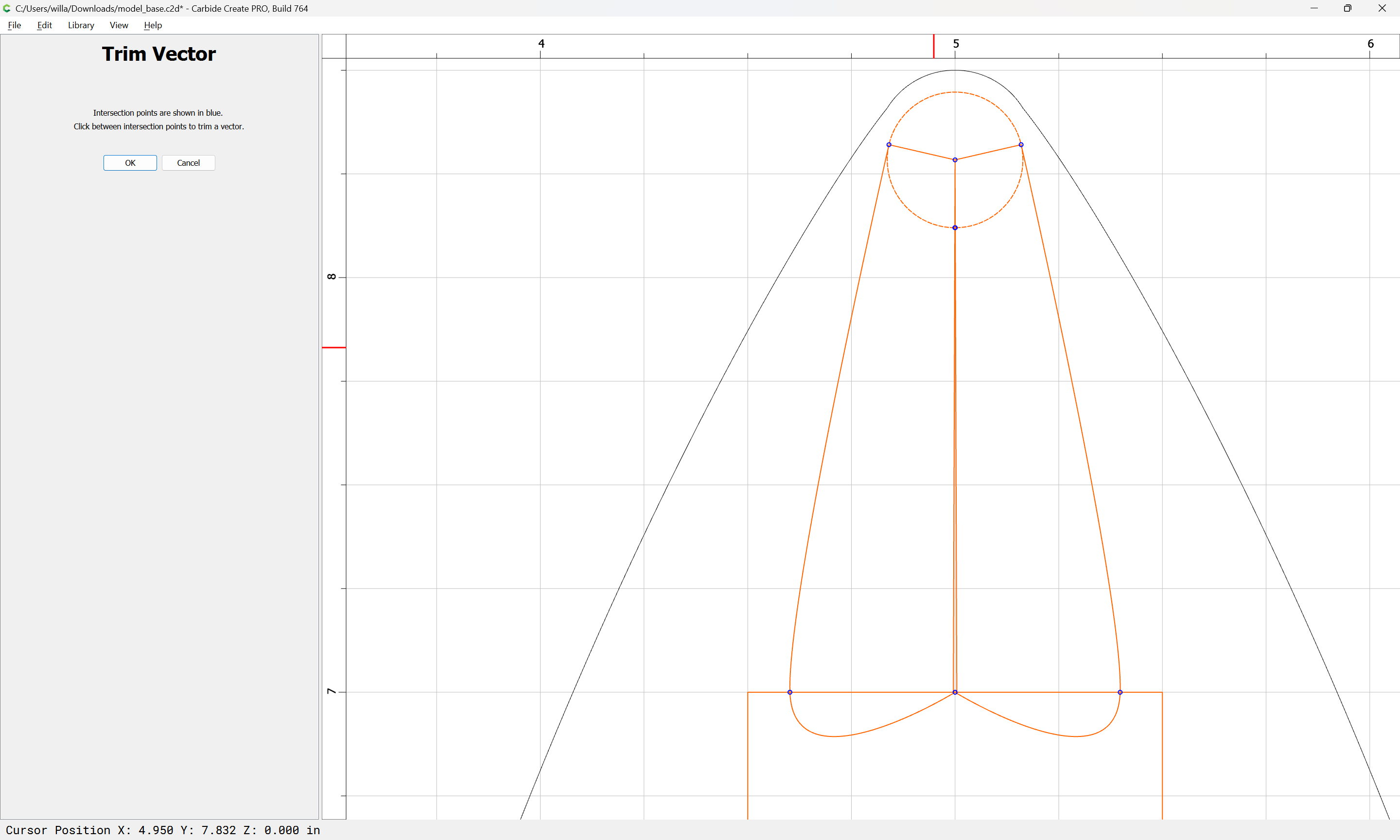
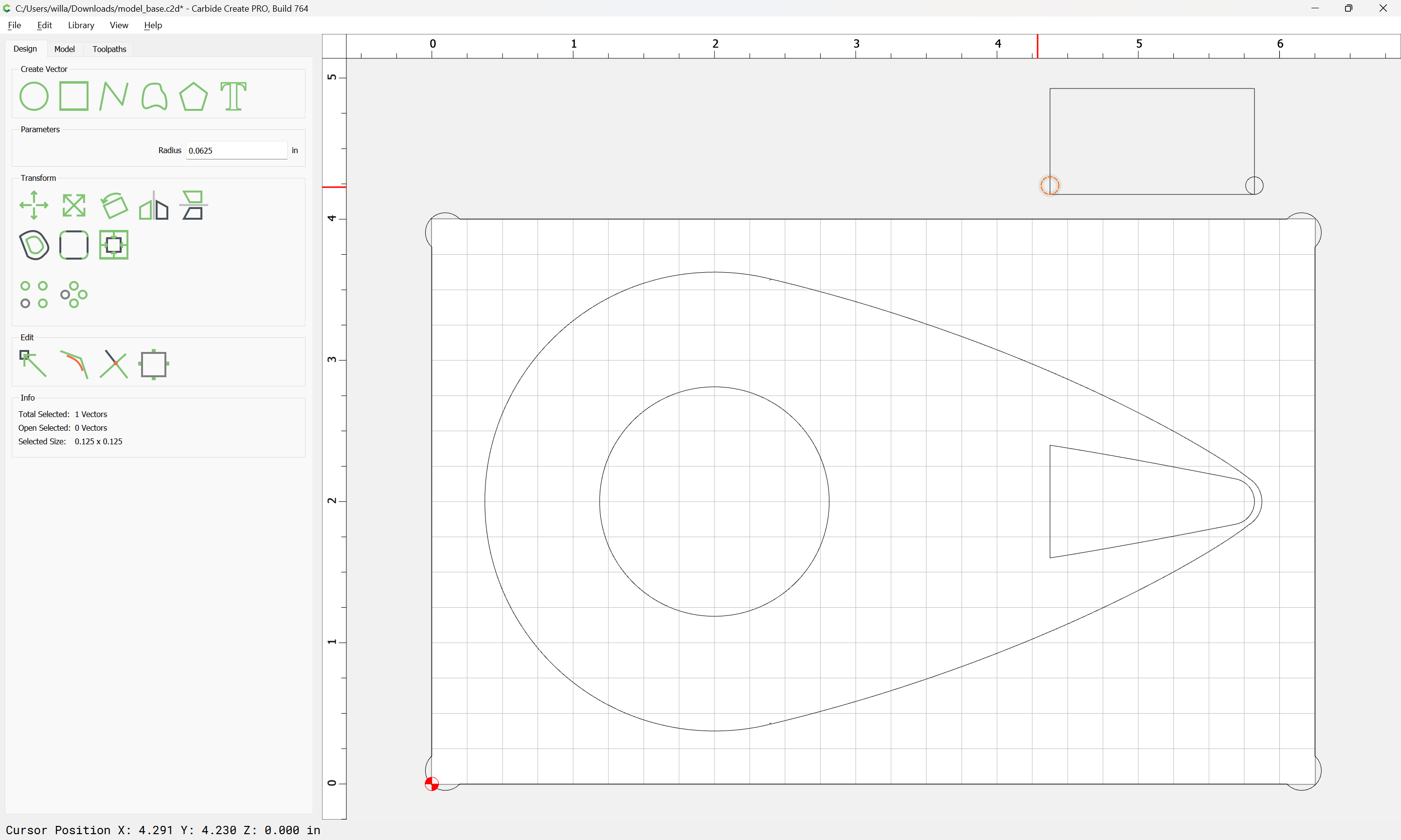
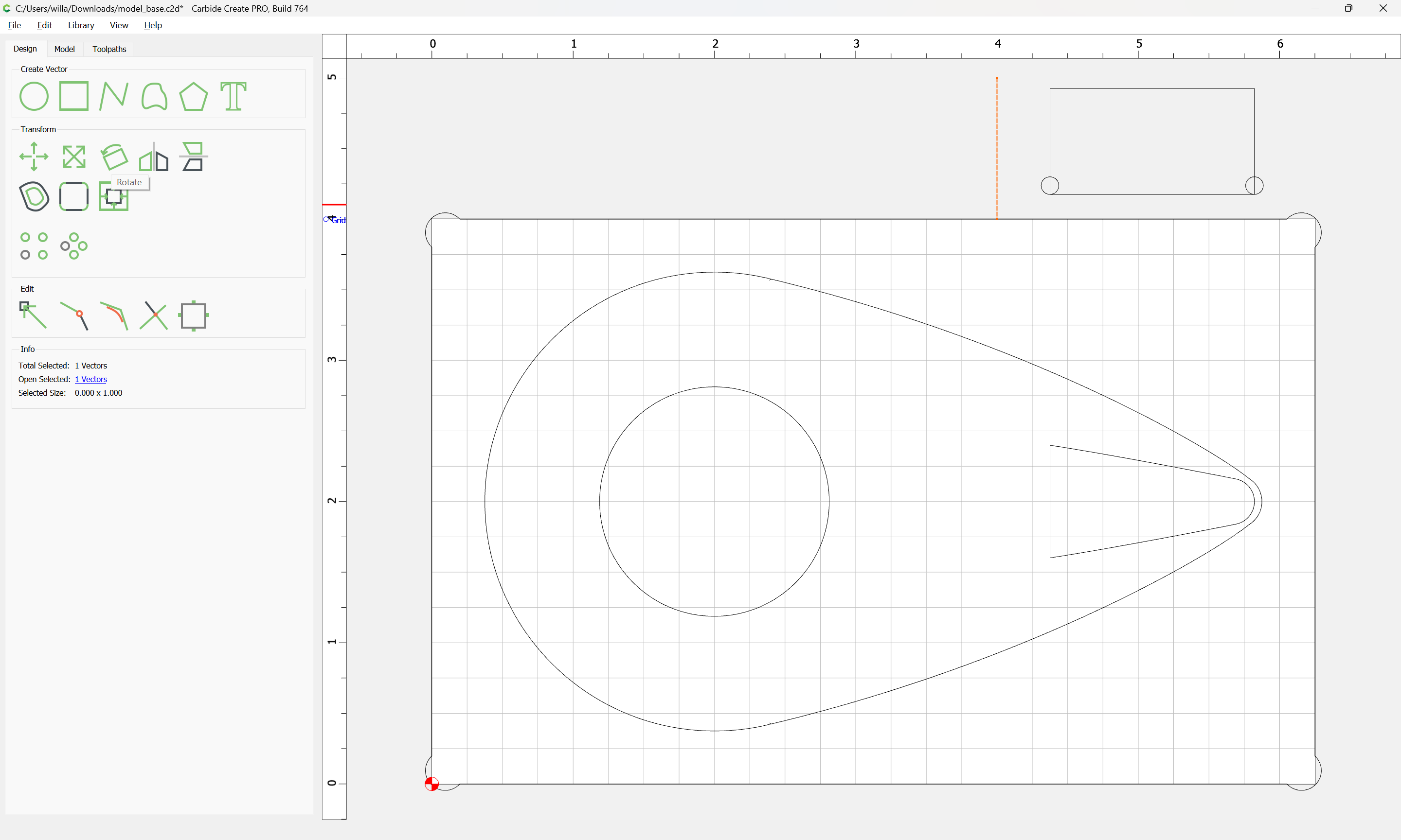
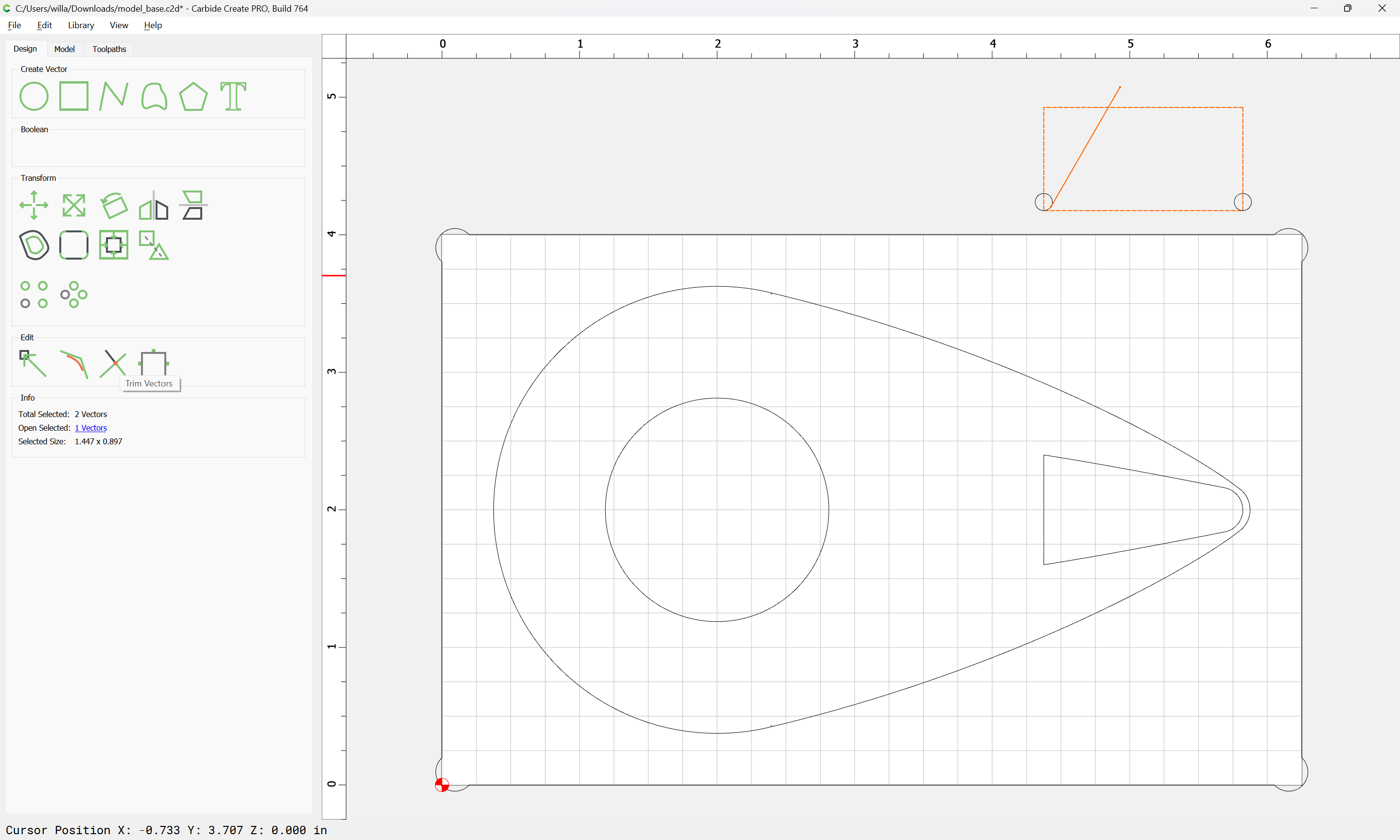
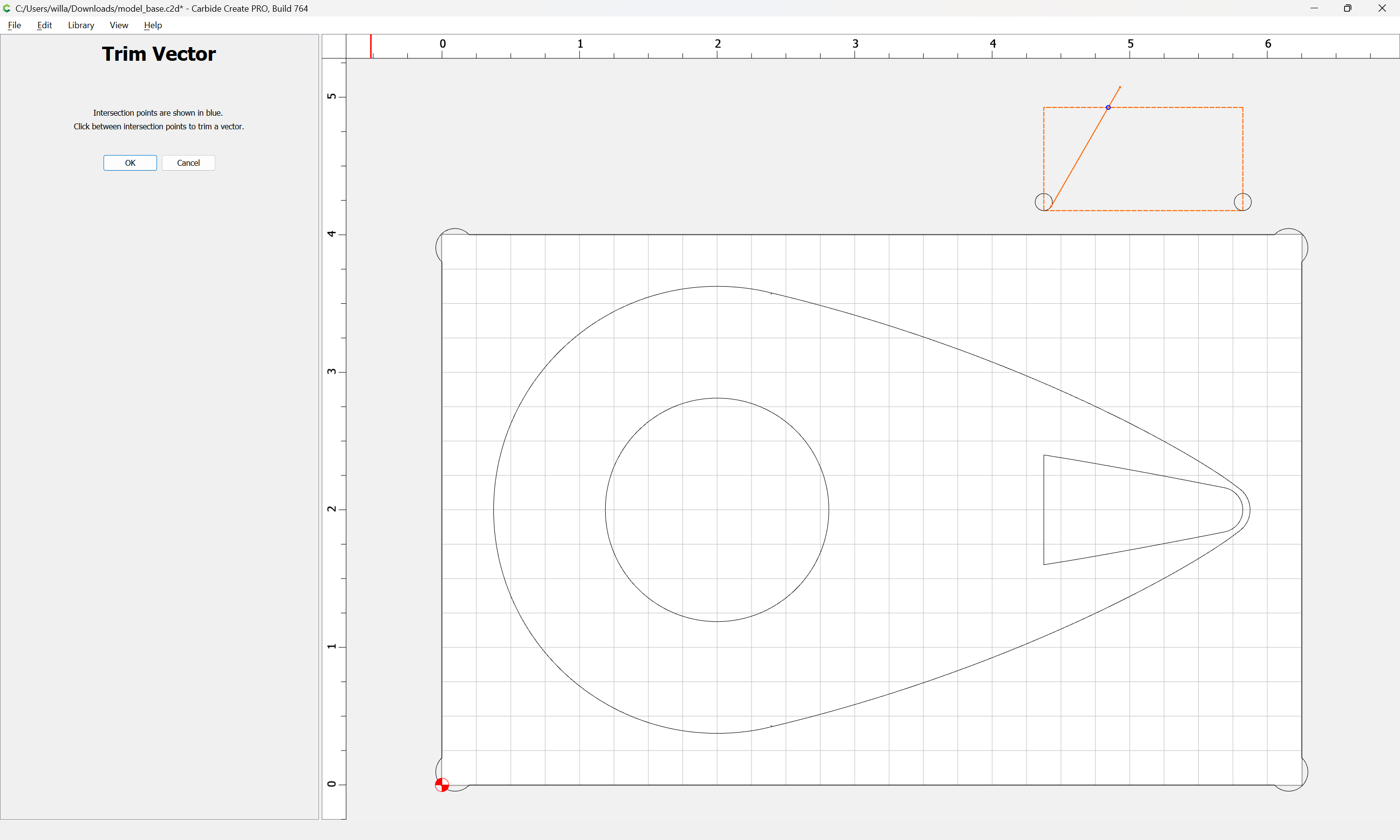
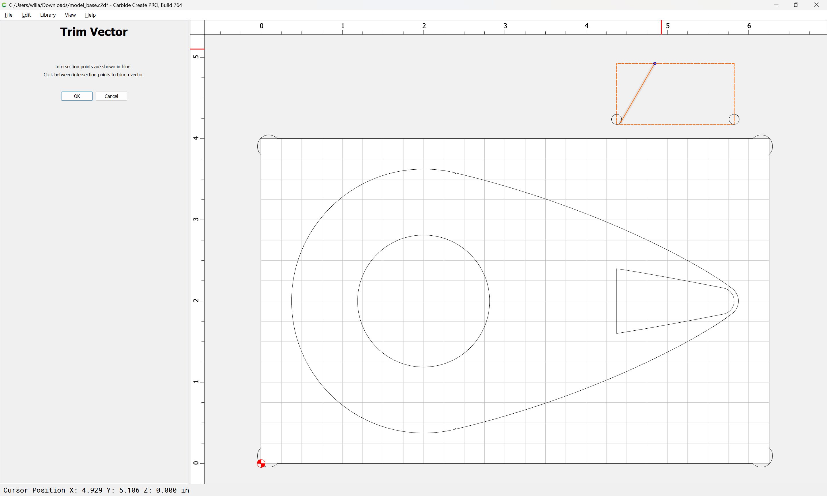
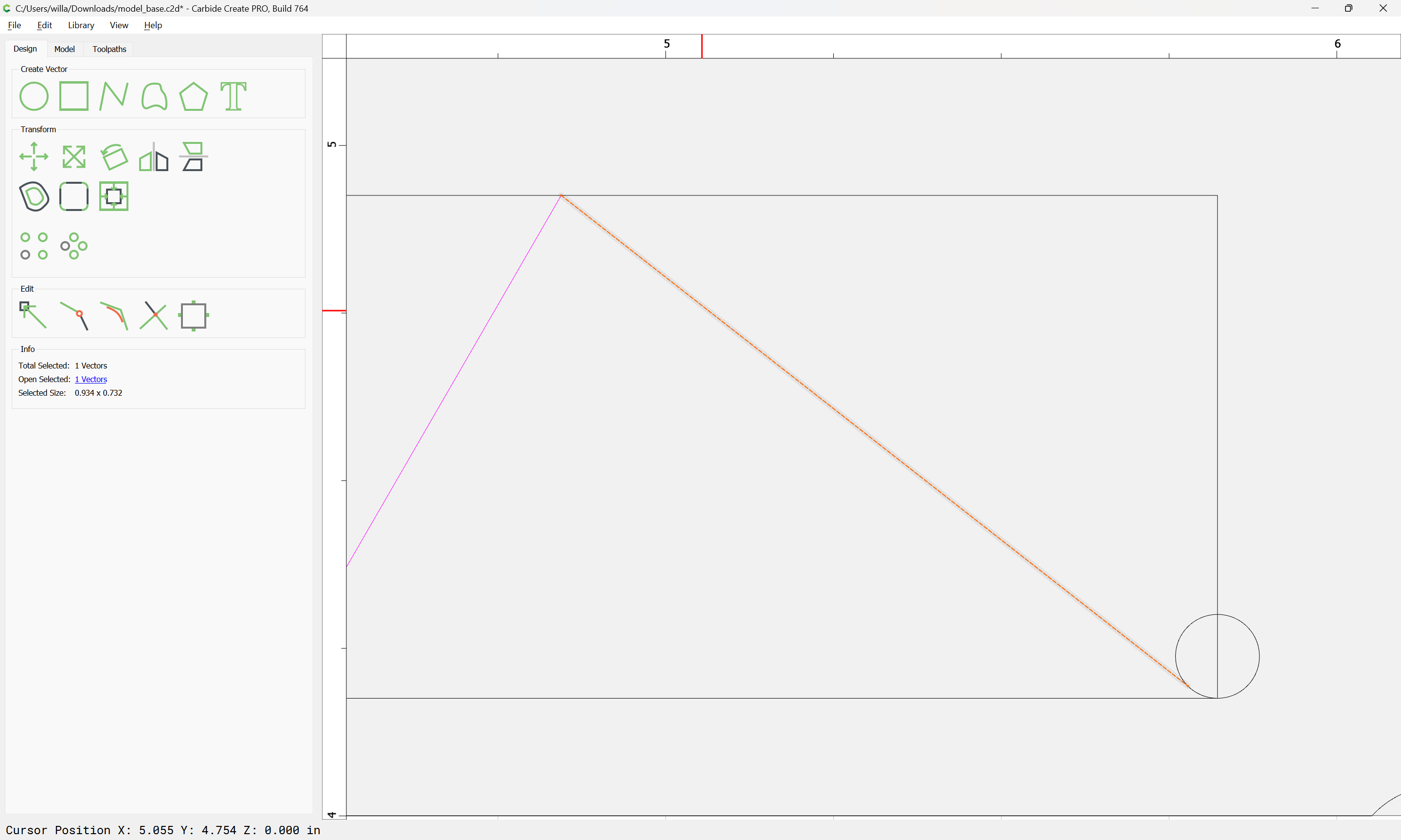
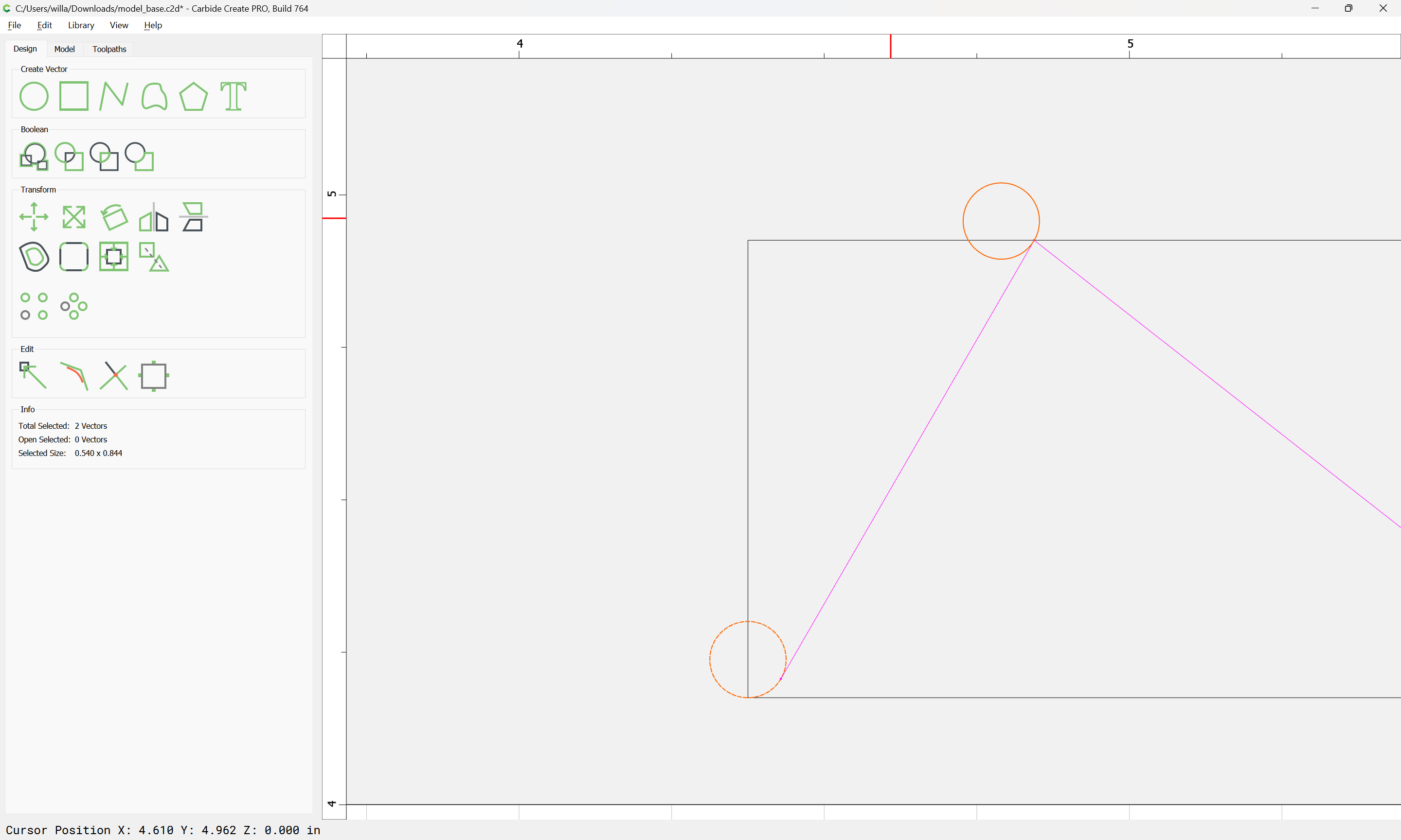
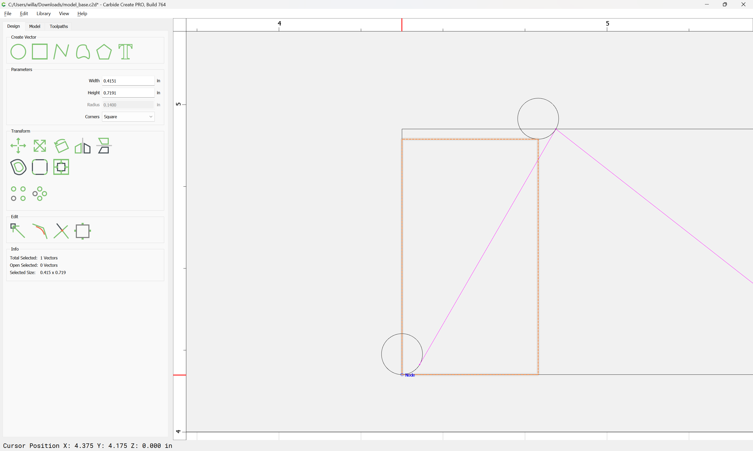
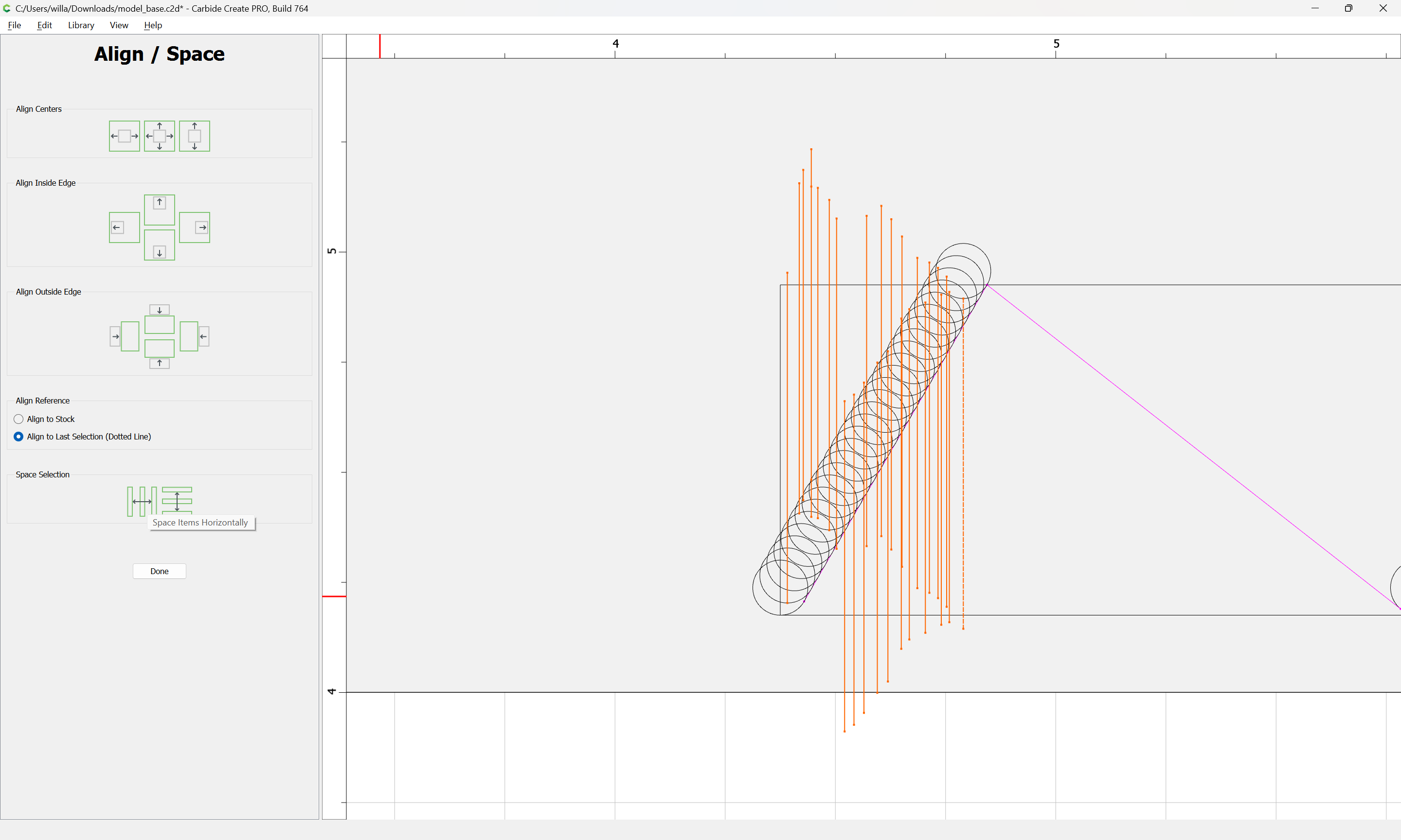
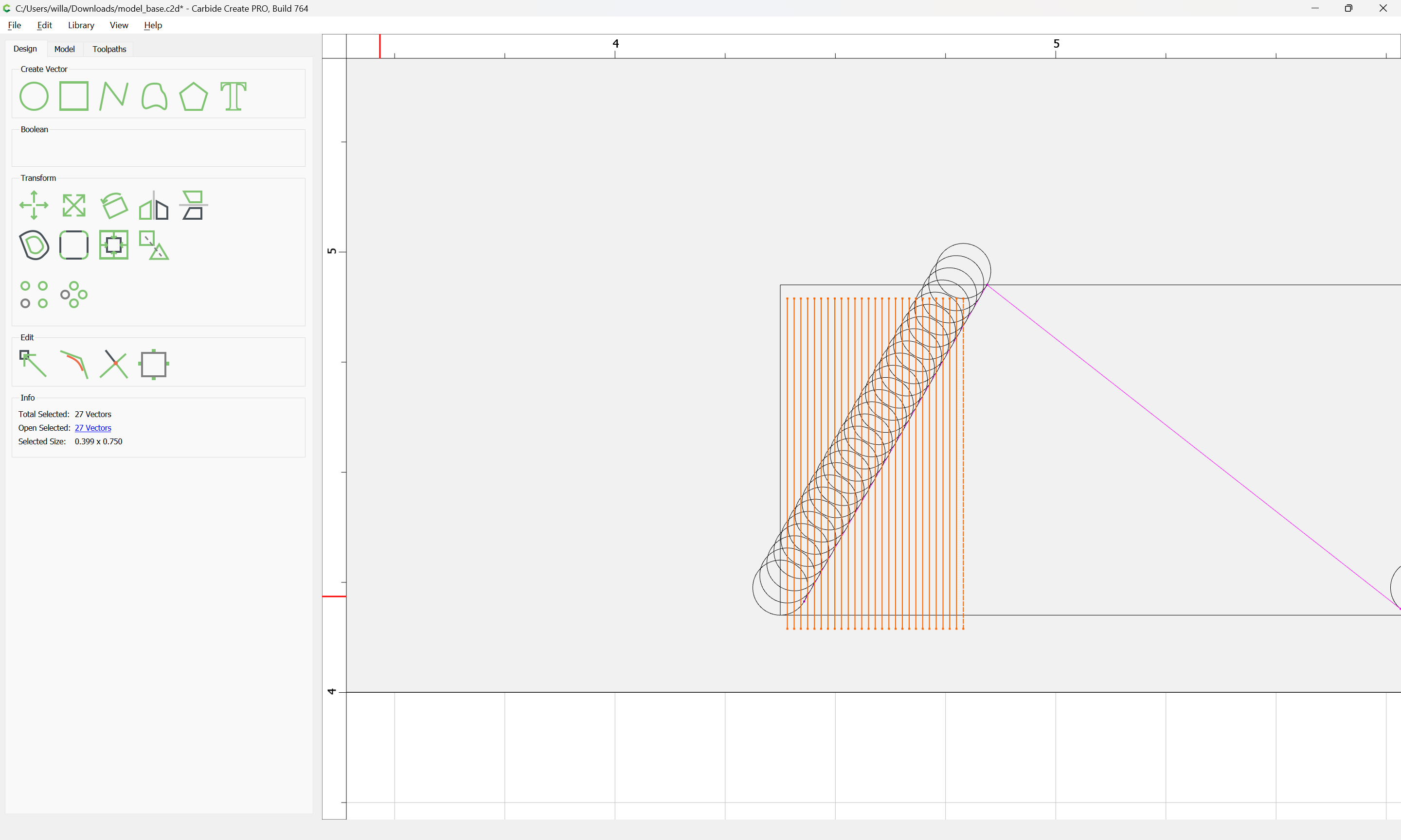
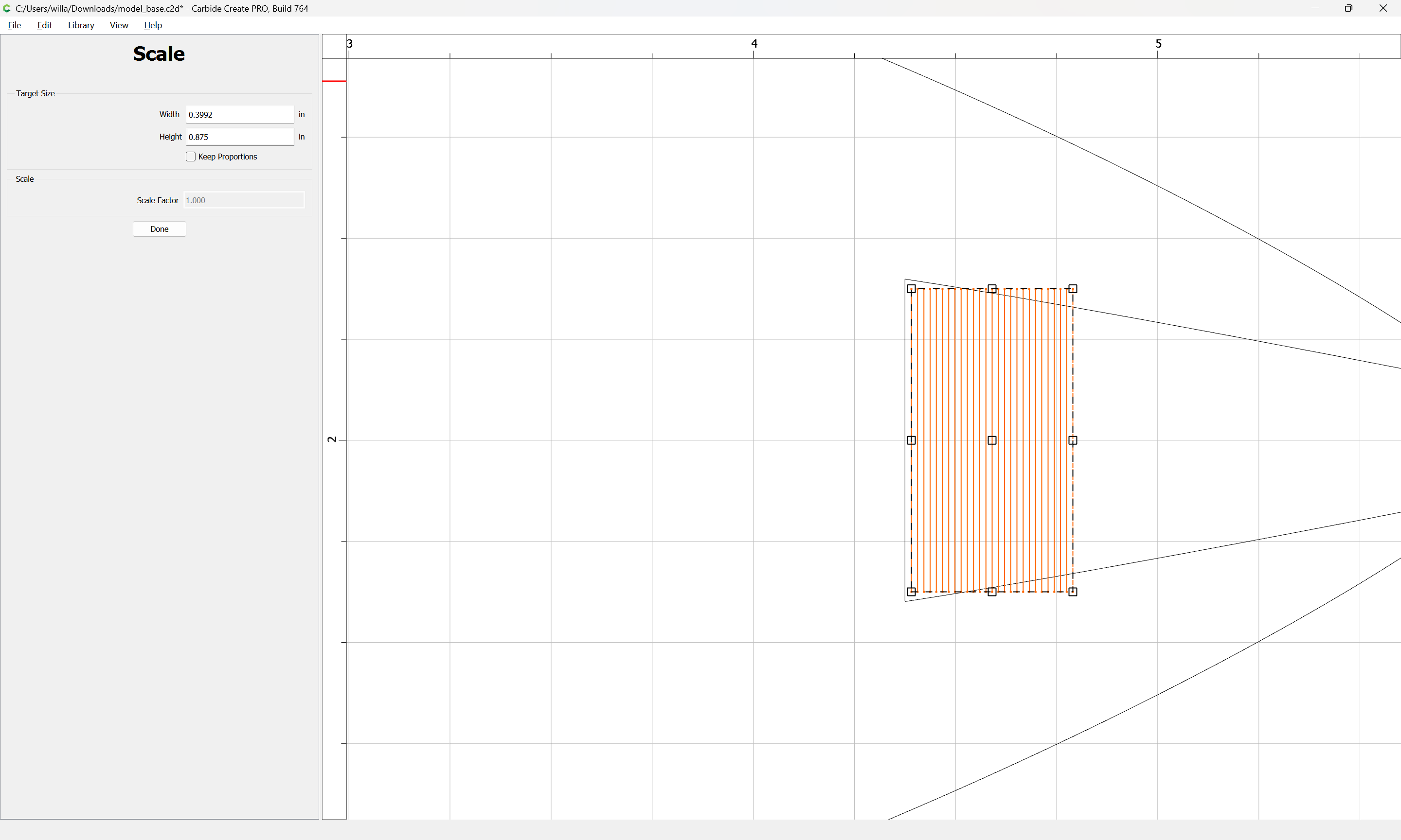
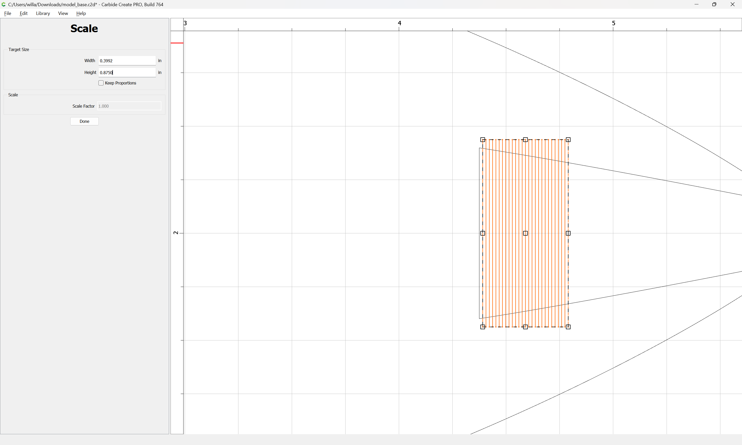
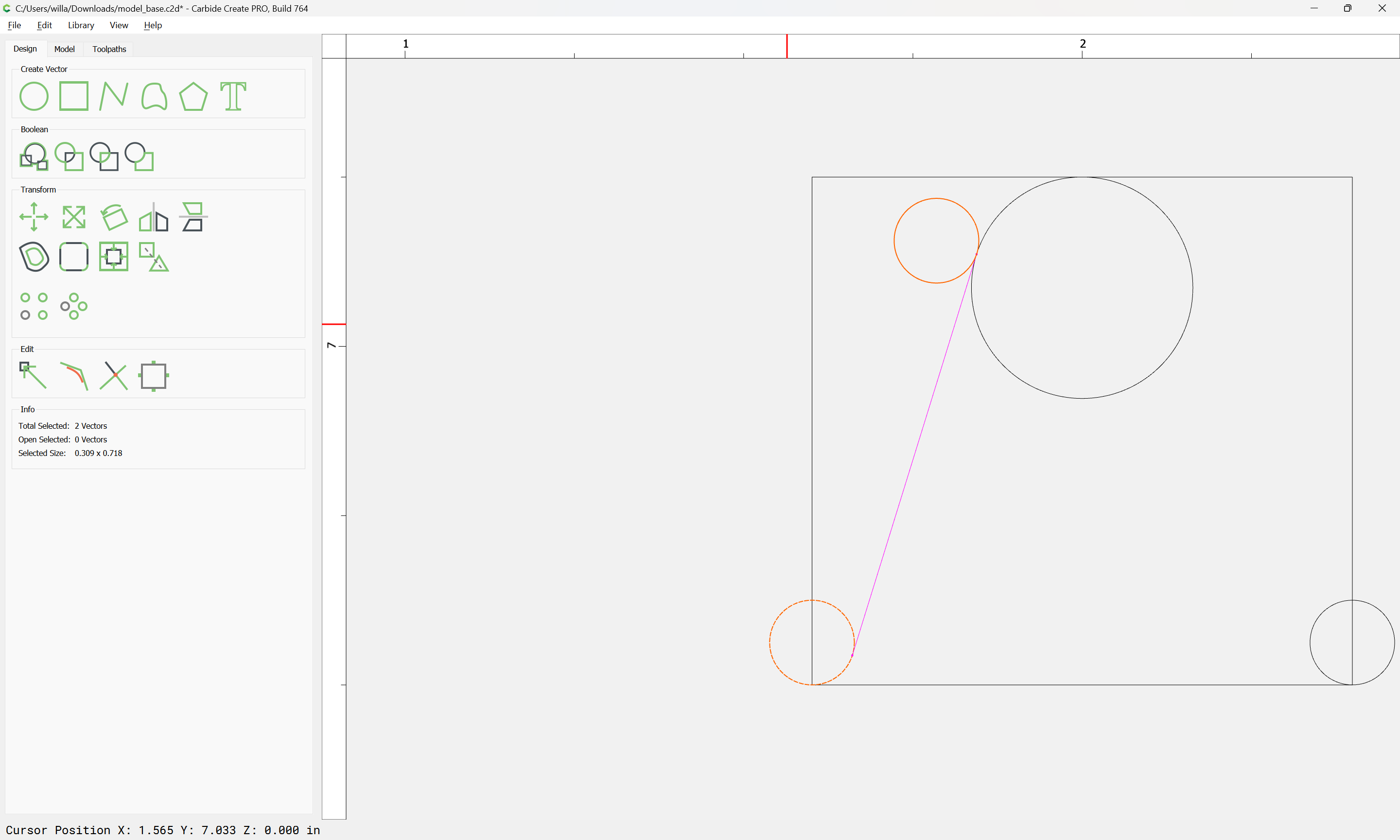
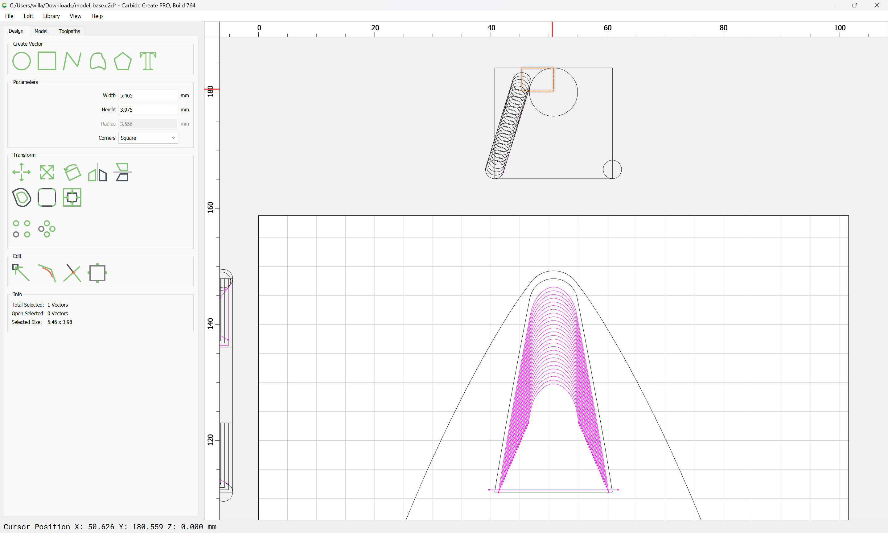
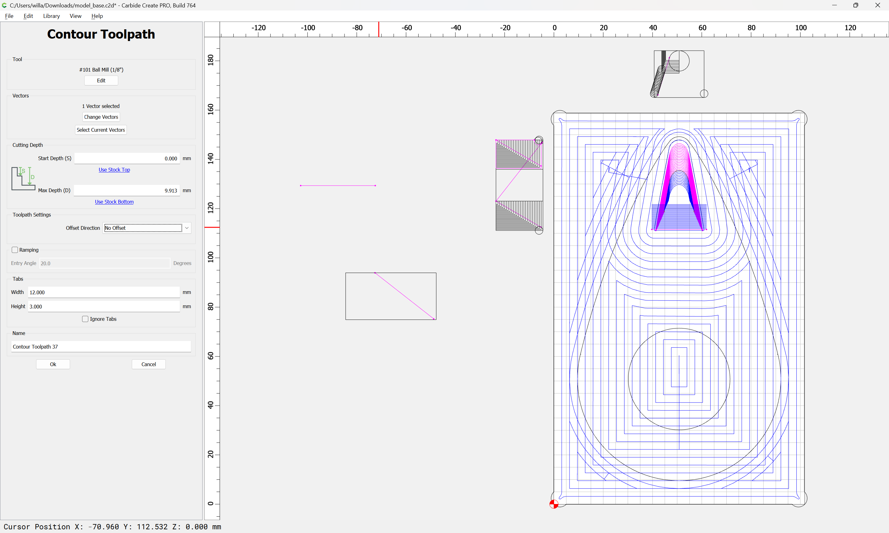
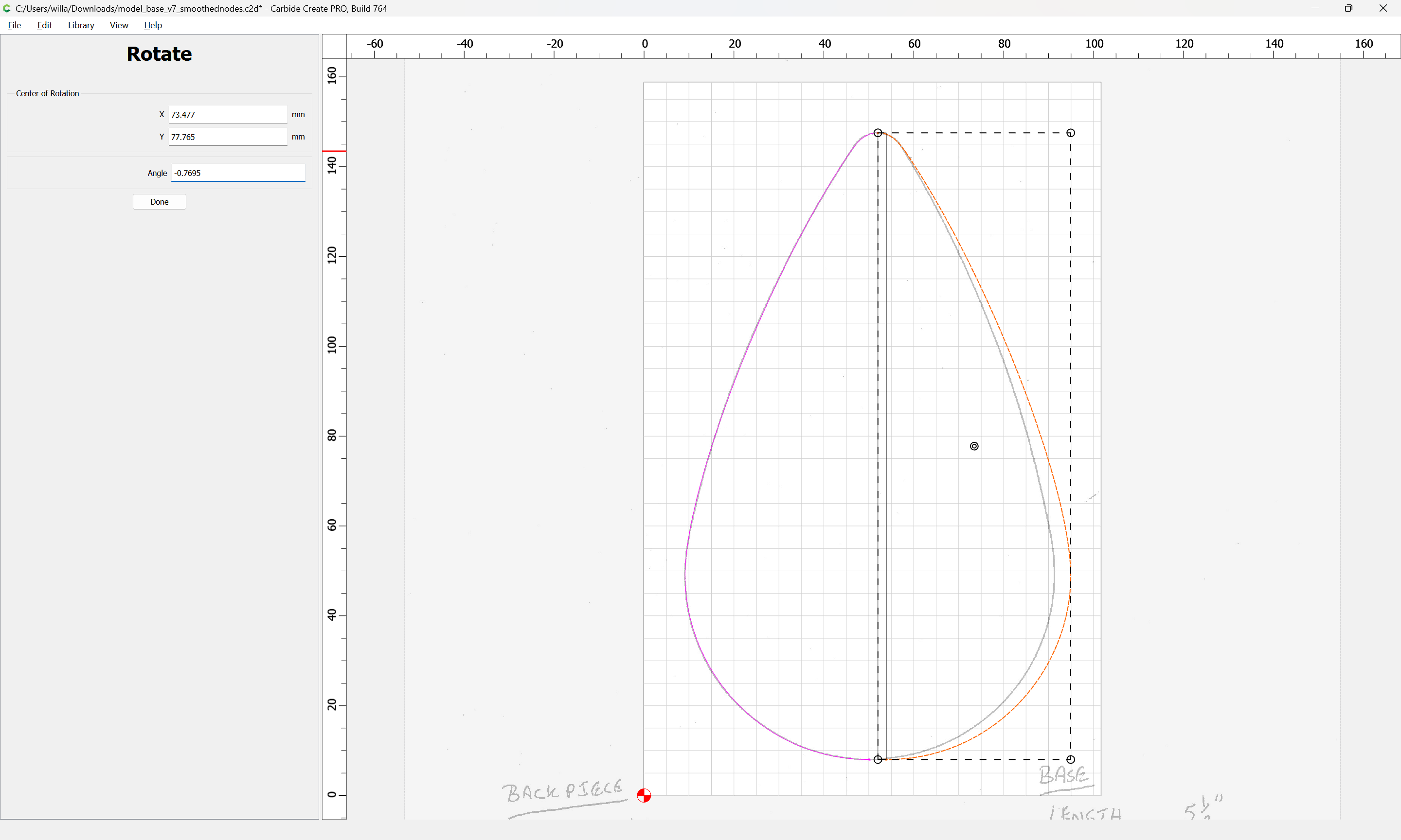
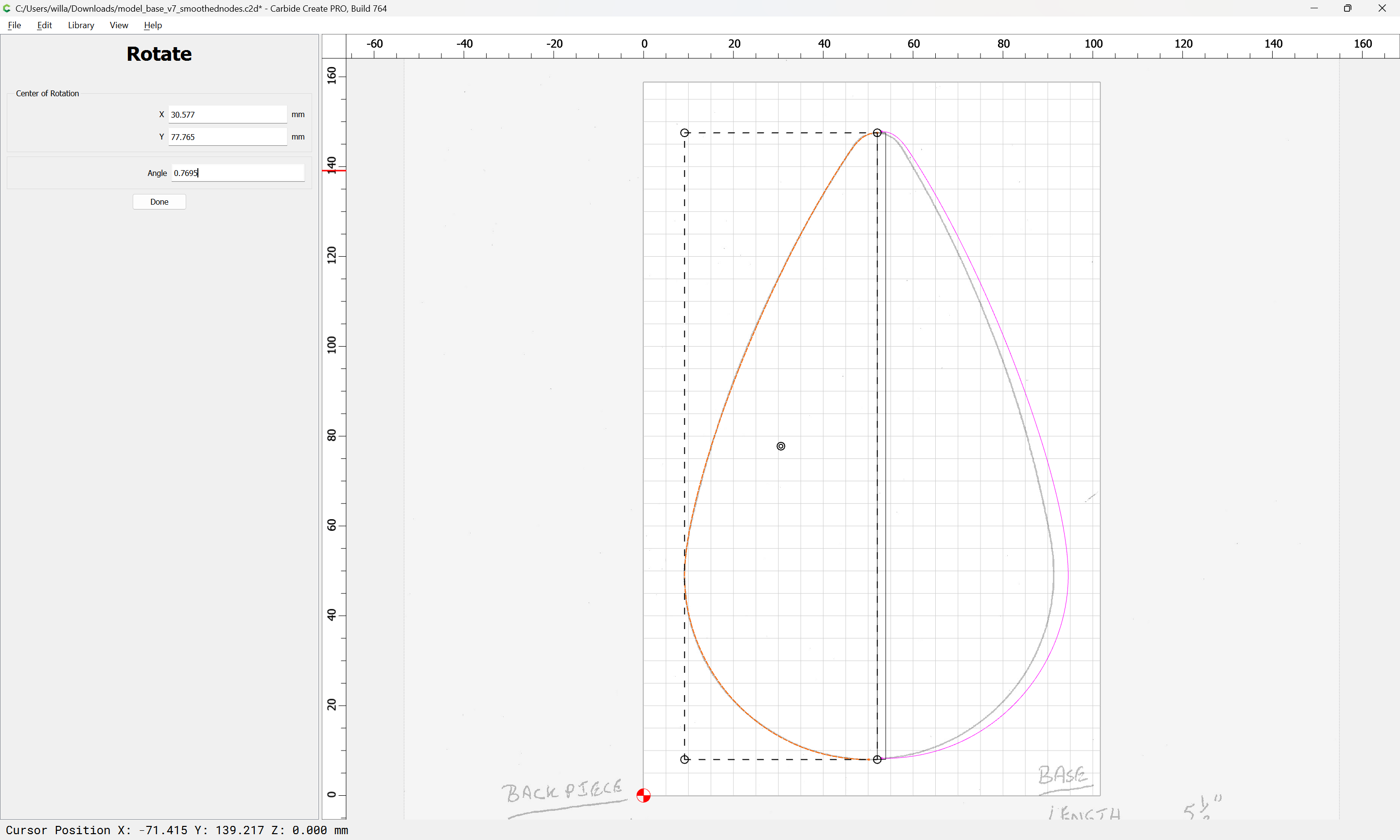
If we draw in a rectangle using the control key (command on a Mac) to get the offset we can get the dimensions of a triangle which we can use a bit of geometry/trigonometry:
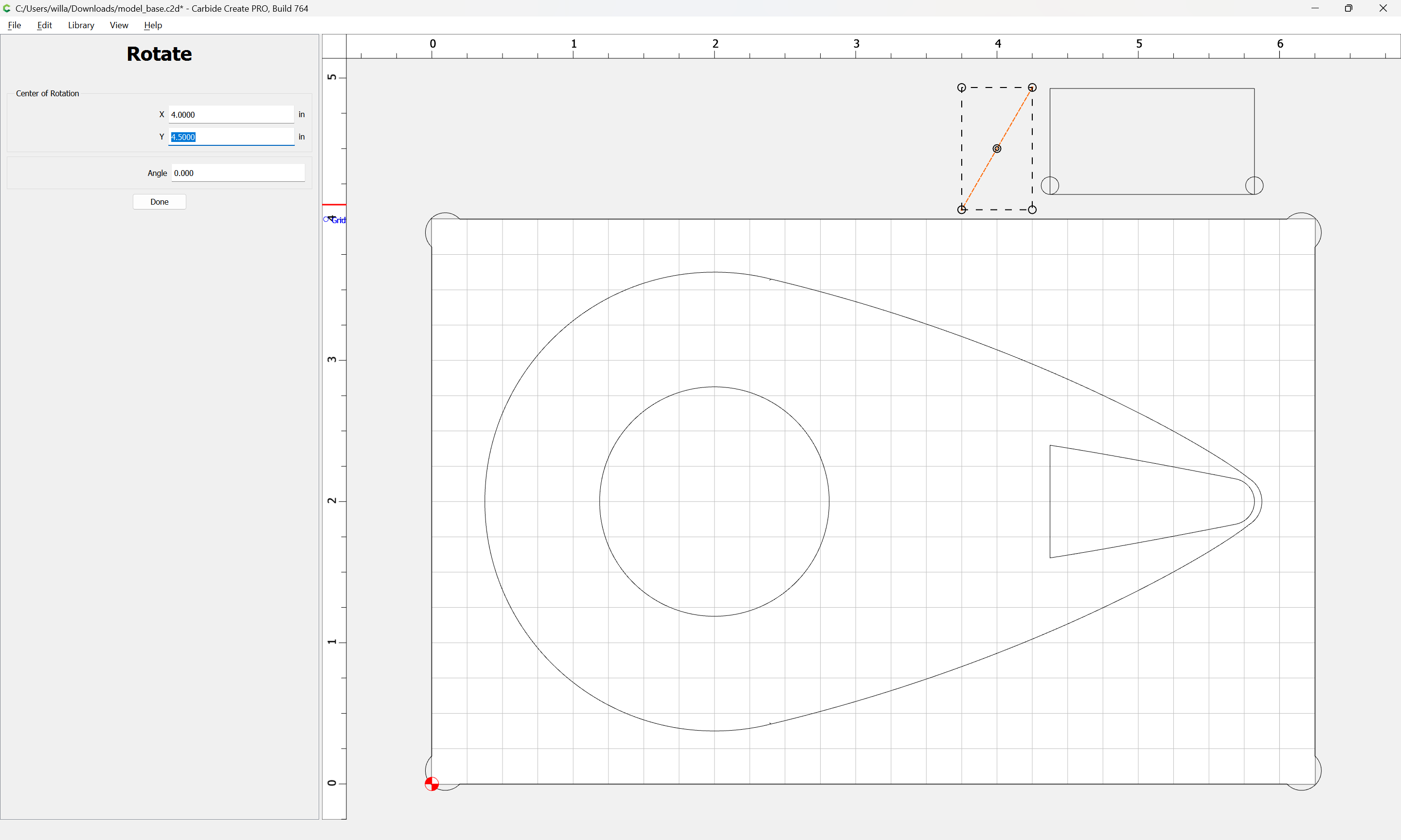
to determine how much to rotate each half to bring them into alignment:
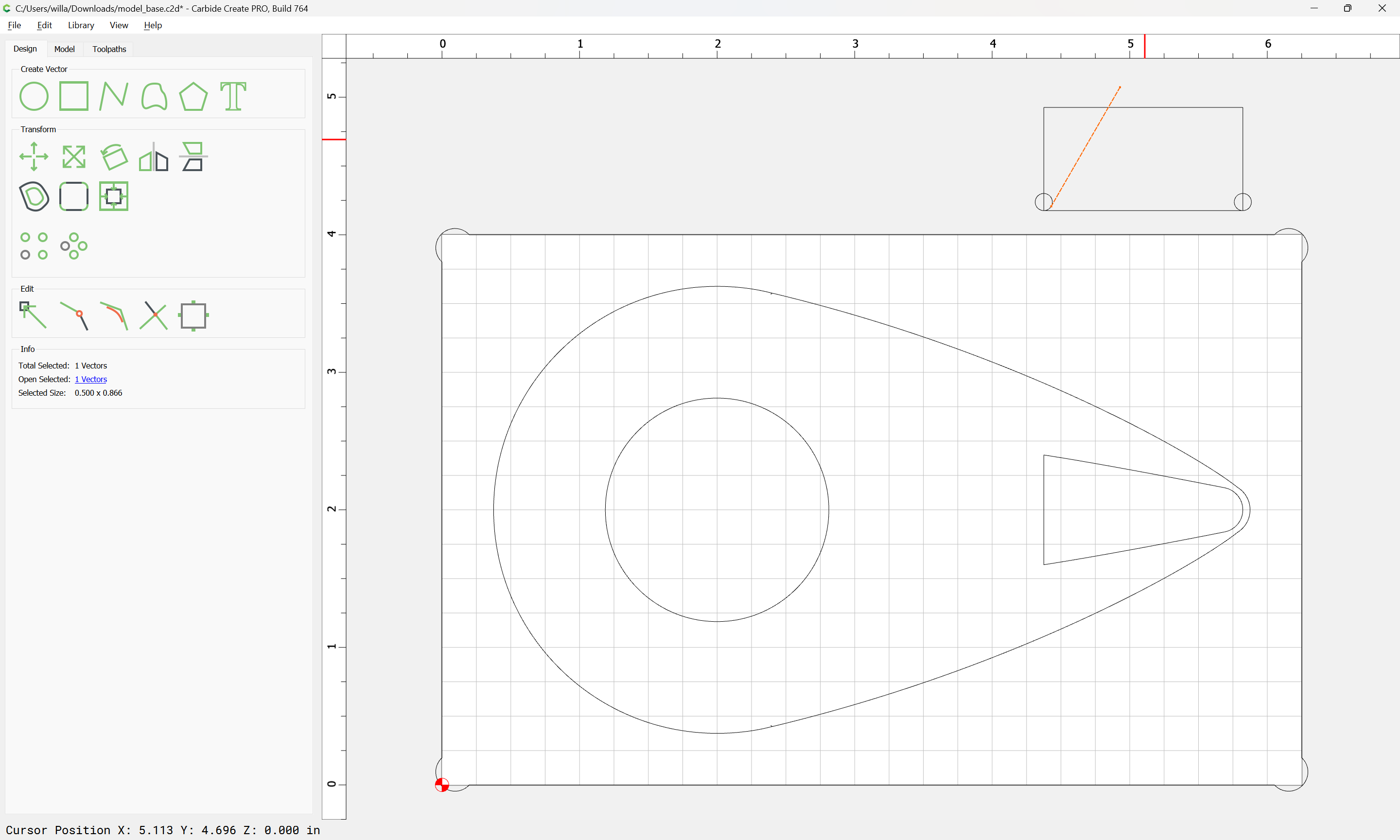
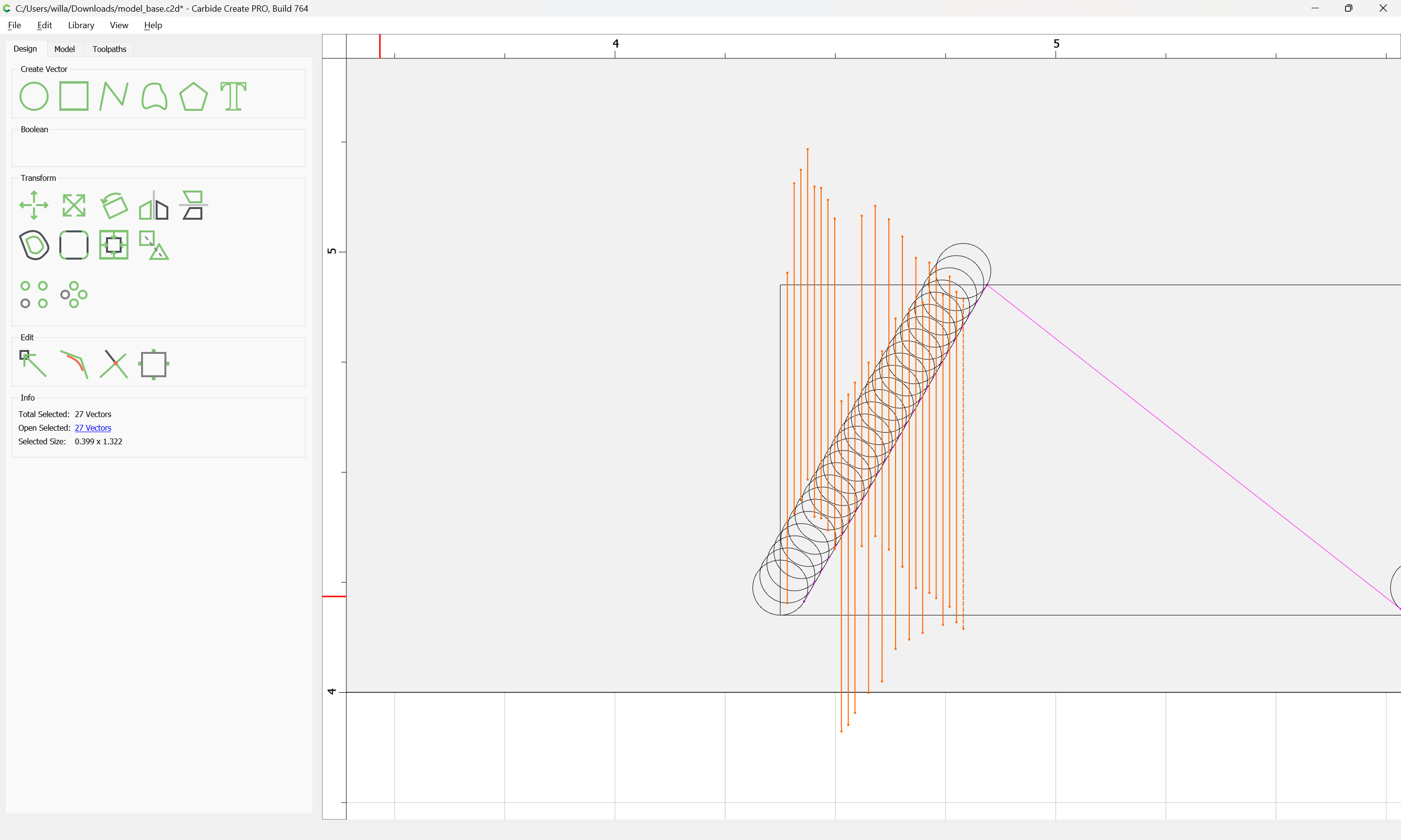
repeat for the other side with the negative/positive of the angle:
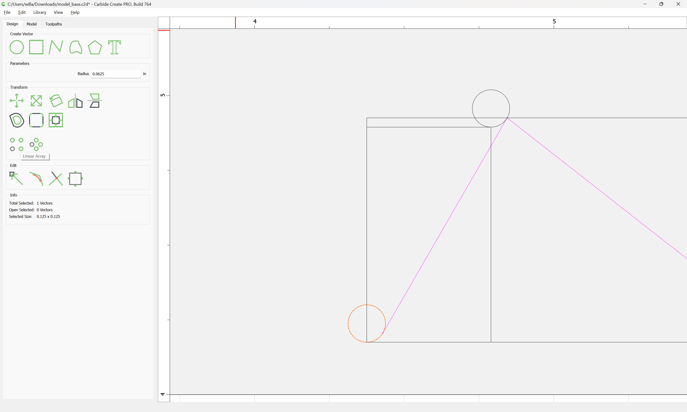
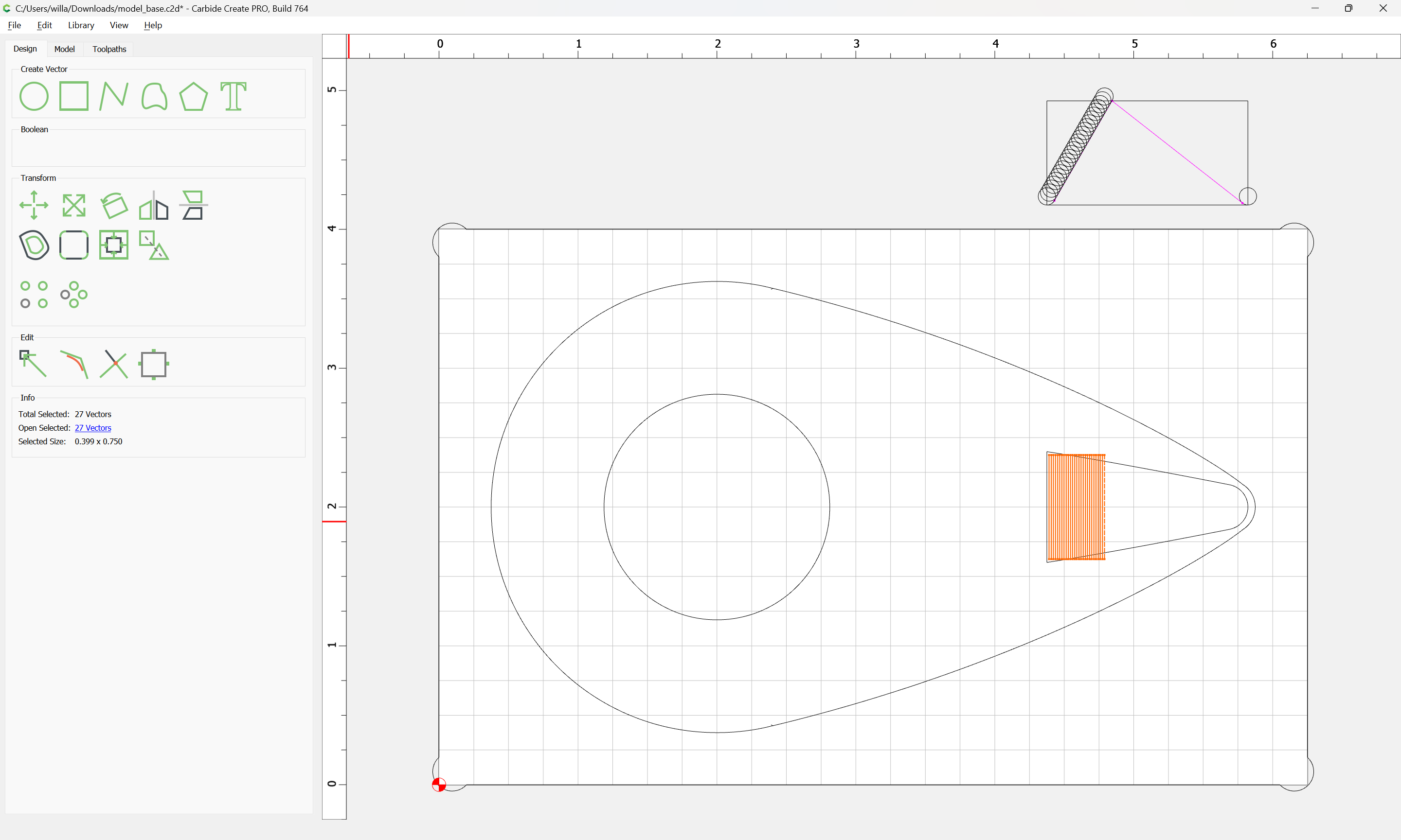
(delete the rectangle)
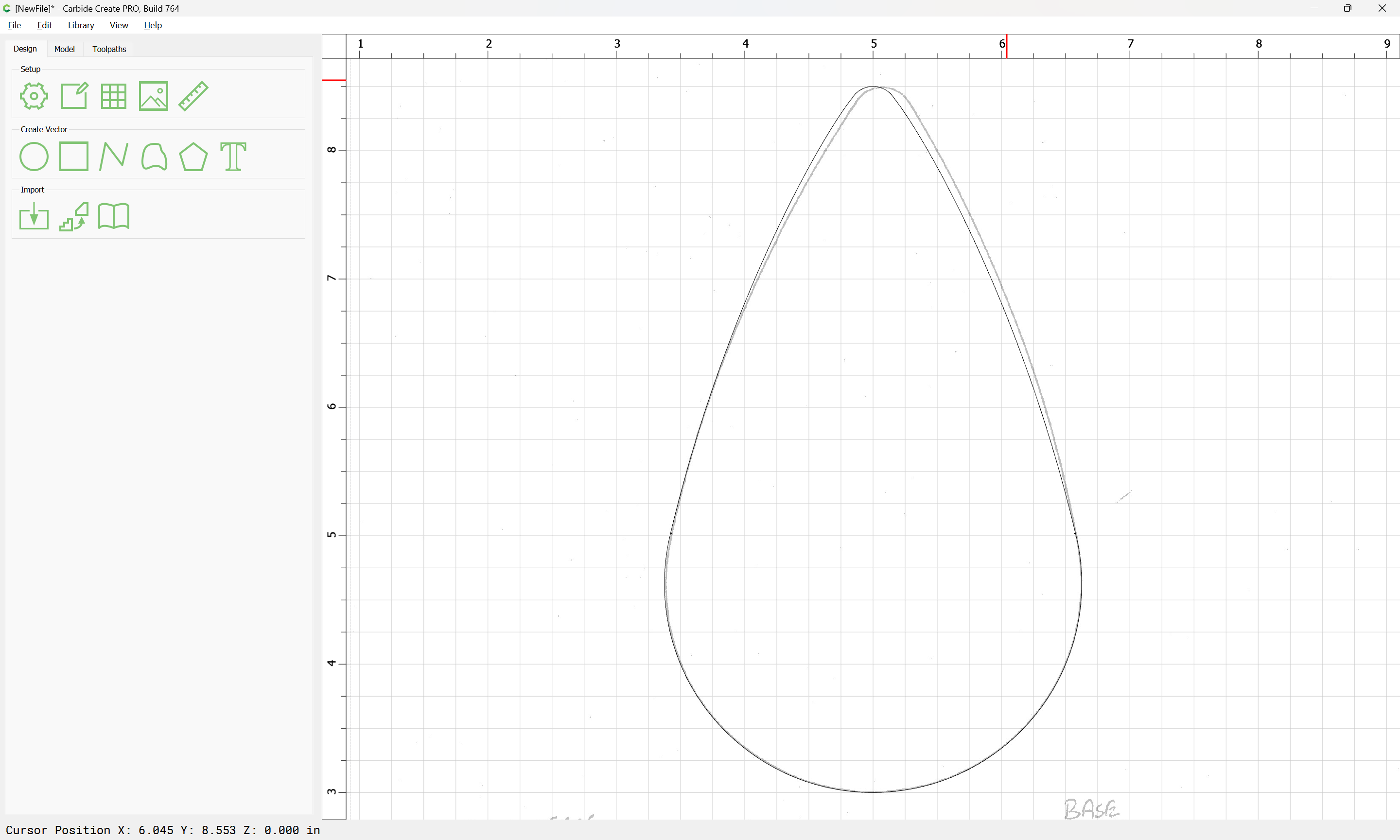
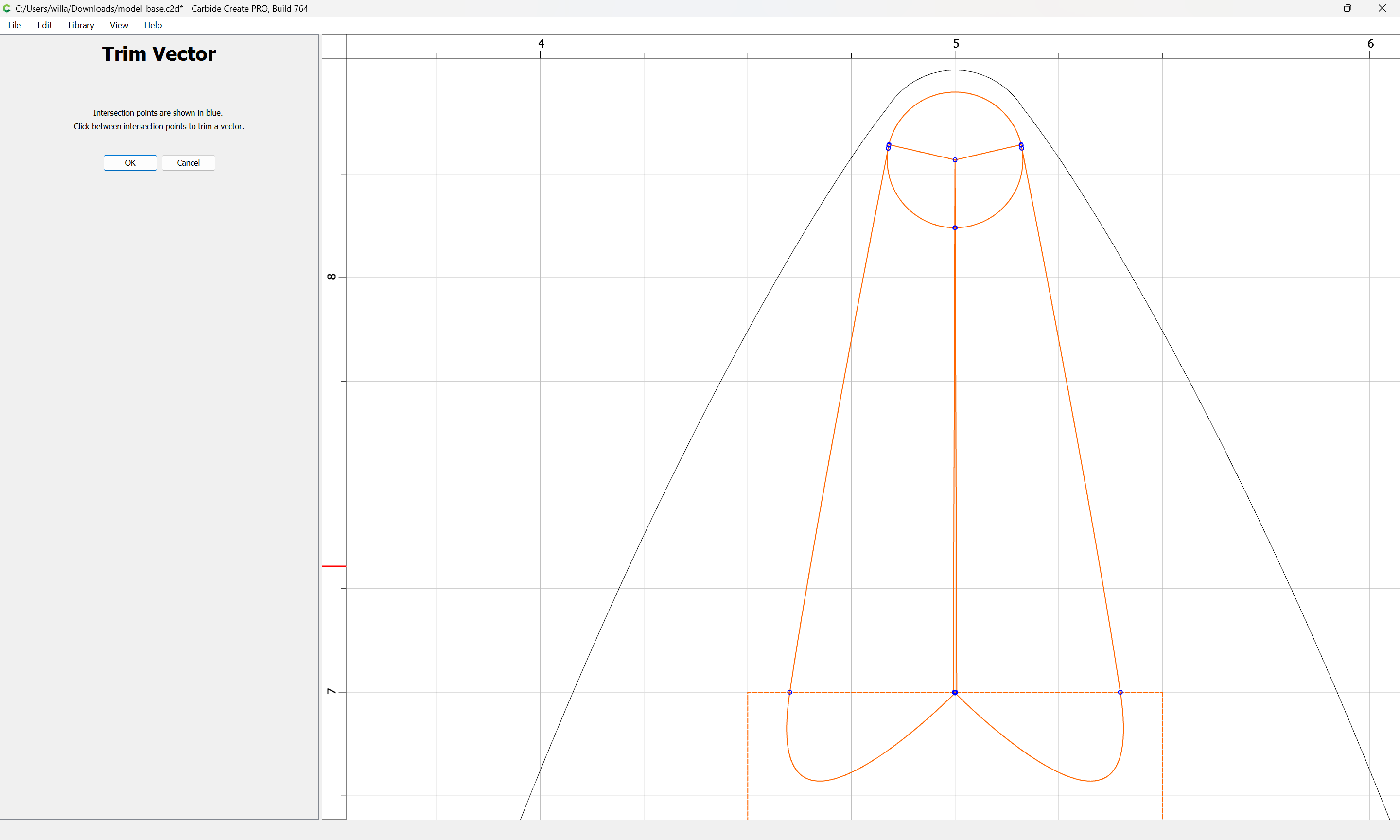
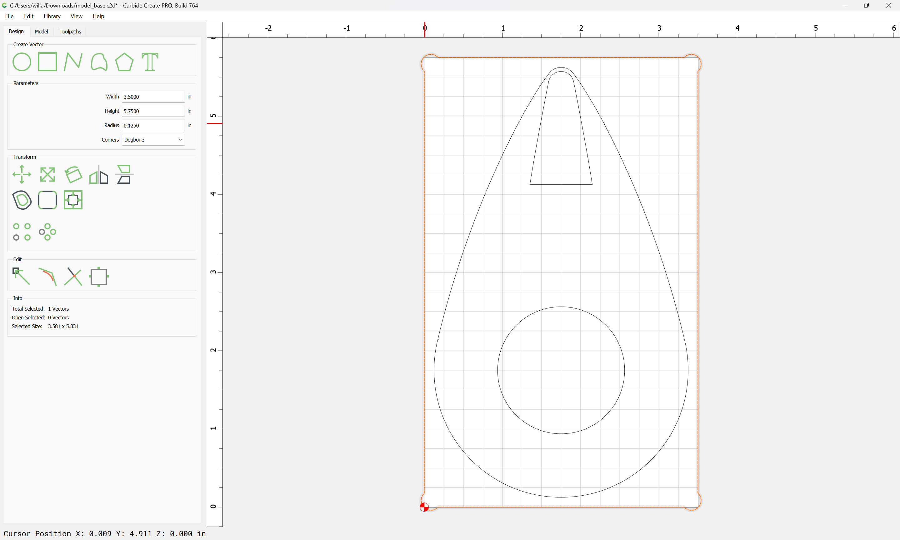
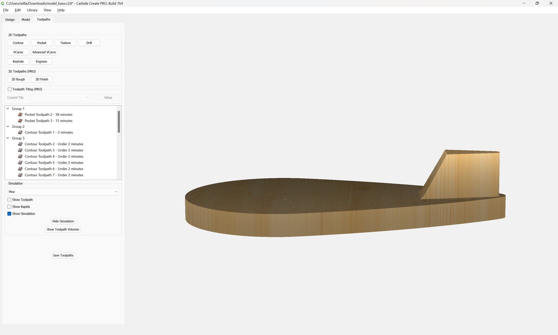
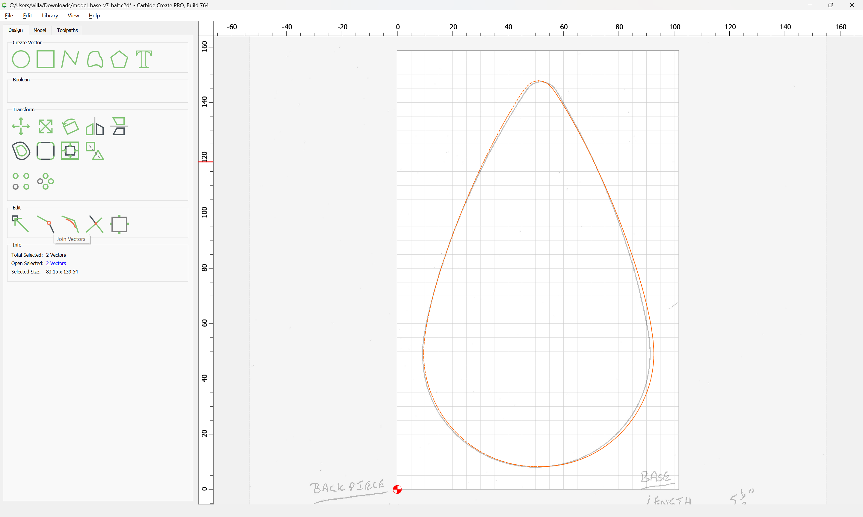
The two halves should now fit together:
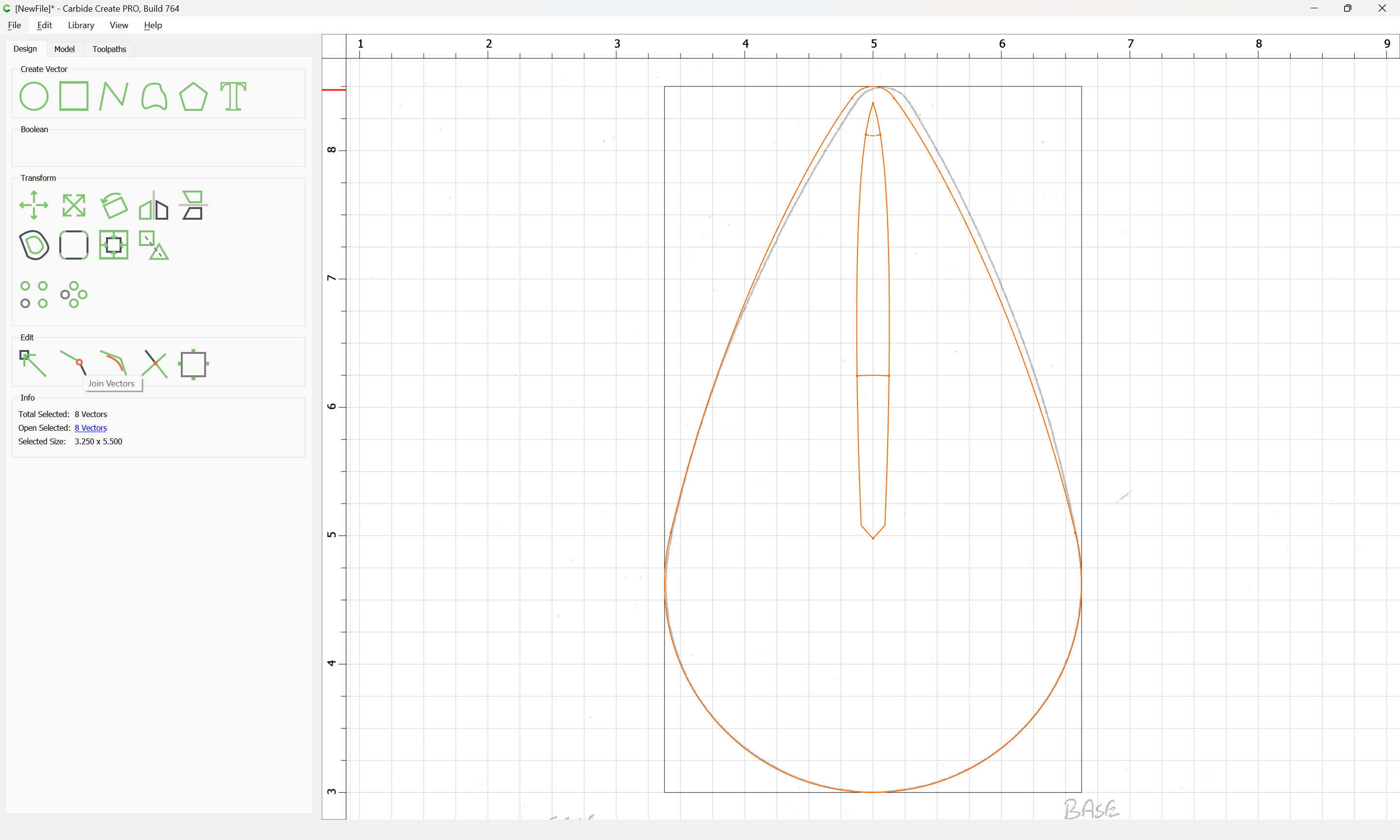
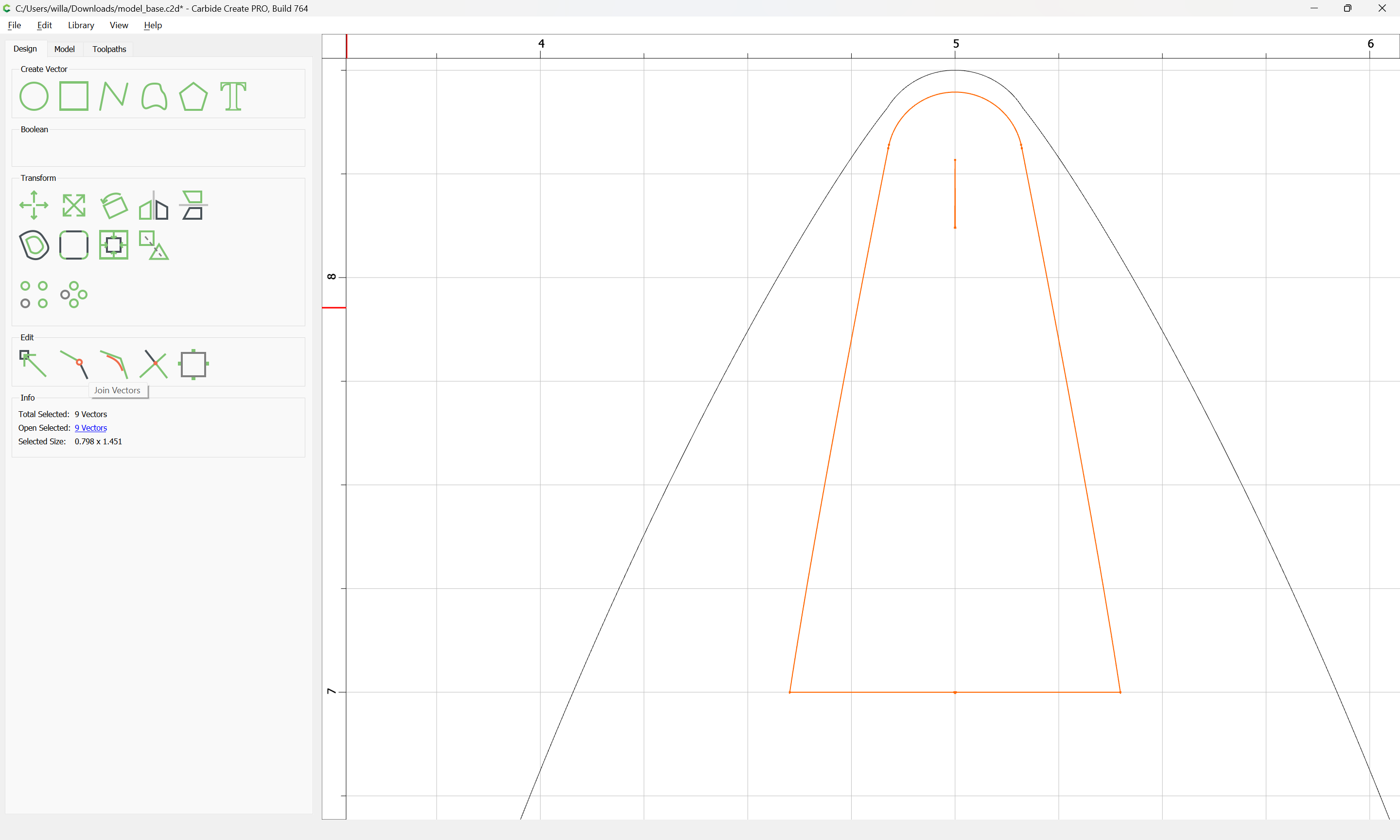
select both:
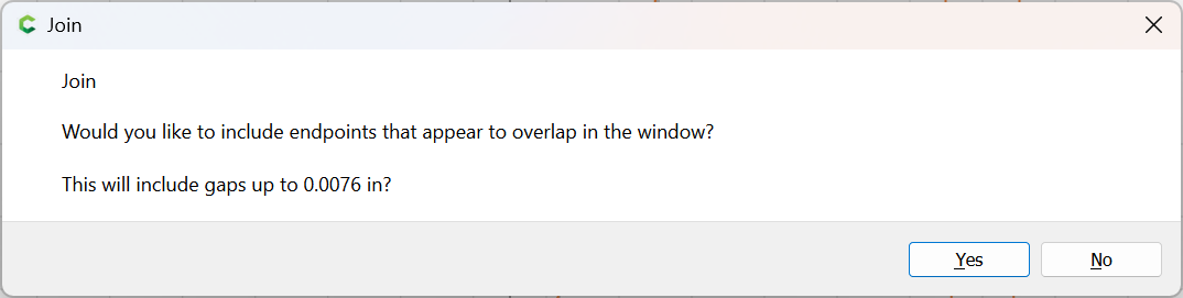
Join Vectors
Yes
If desired, go into Node Edit mode and smooth out the top node.
model_base_v7_outline.c2d (236 KB)