Step-by-step instructions were shown above.
What is your favourite text editor?
Do you have Carbide Create Pro?
Or, is using Autodesk Fusion 360 an option?
Step-by-step instructions were shown above.
What is your favourite text editor?
Do you have Carbide Create Pro?
Or, is using Autodesk Fusion 360 an option?
can i edit text in word?
I don’t have pro, i just have the starter one carbide create.
I haven’t tried any other software just yet, was trying to get to grips with carbide first
Yes, Word can be used as a text editor, but you have to account for any changes it might make, and be certain to save in .txt format.
Notepad would be better to use.
If you get the free/opensource Notepad++ then you can use the NCnetic G-code previewing plugin as noted above.
Thankyou, i go the text saved from the file above 1-p.nc, is that correct?
can i just edit the g-code when i have the file open in carbide create to add this in?
The sequence is:
Thankyou William, i will have a go.
Hello William.
Can i ask, when i have the file above open in notepad ++ what do i select as a file to save it as to be able to put into the machine?
Re-save as a .txt file, if need be, add the file extension .nc back.
Thankyou William, i had a go and got them to slope!
Can i ask, how do i get them to be 330mm overall span instead of 190mm?
It should work to just select the lines and scale, then carry out the balance of the process with the new file.
Hello William.
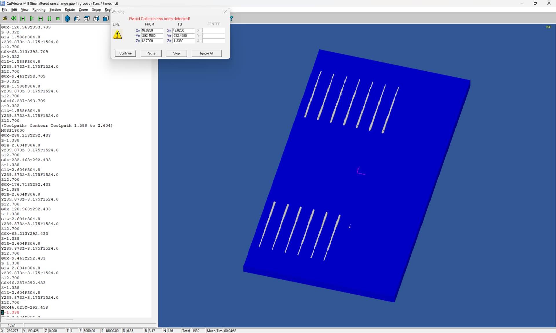
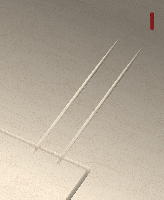
I have tried this file with the edited sections added, having a touch of trouble with the grooves, ideally trying to make the 330mm long all in and it seems to do random slopes, the sink cutout seems to be working ok though, is there anything obvious i have missed?
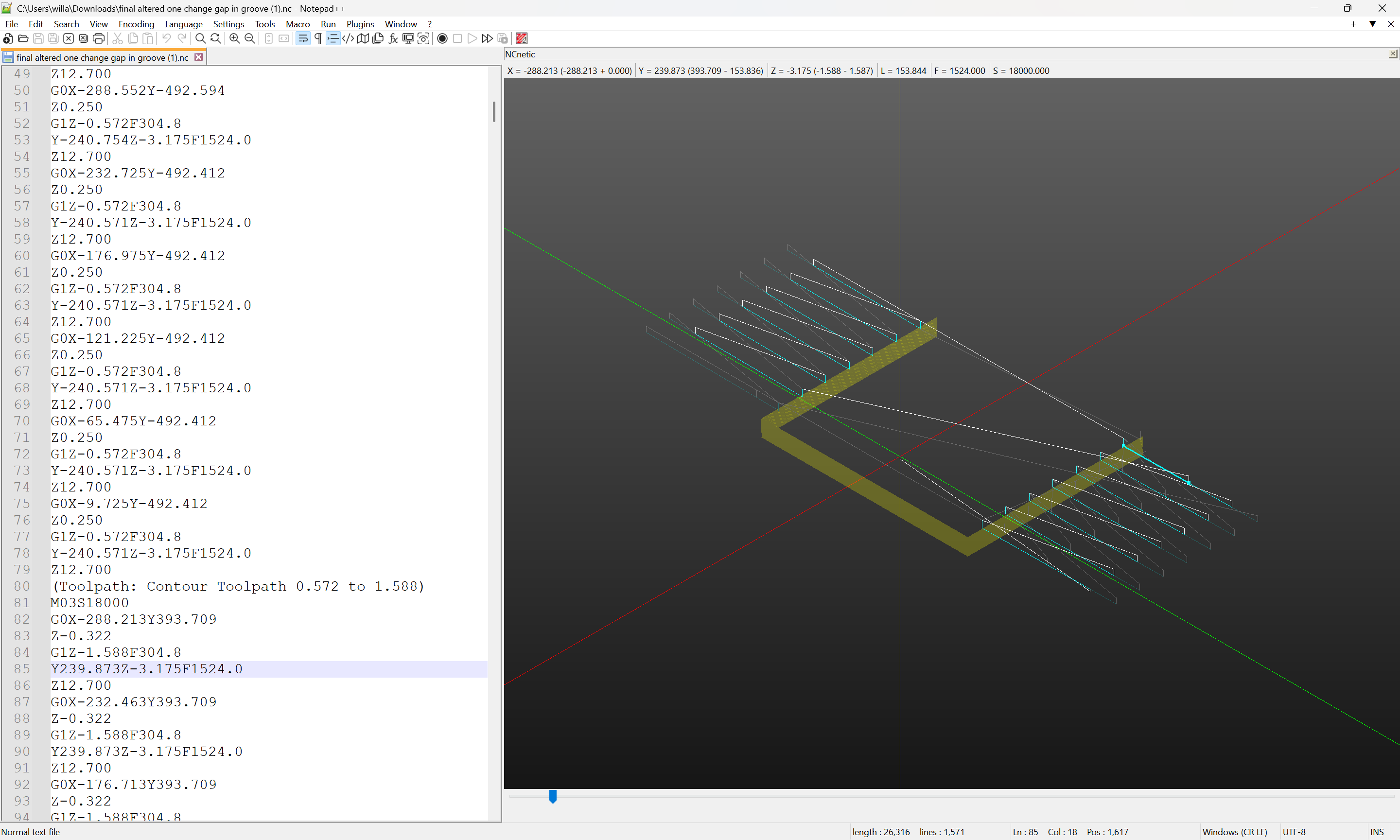
final altered one change gap in groove (1).nc (25.7 KB)
The partial movements seem to have been edited for a Z-axis movement as well:
(and they come after the full length move)
Other than that it seems okay:
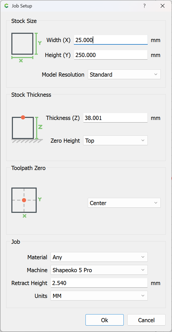
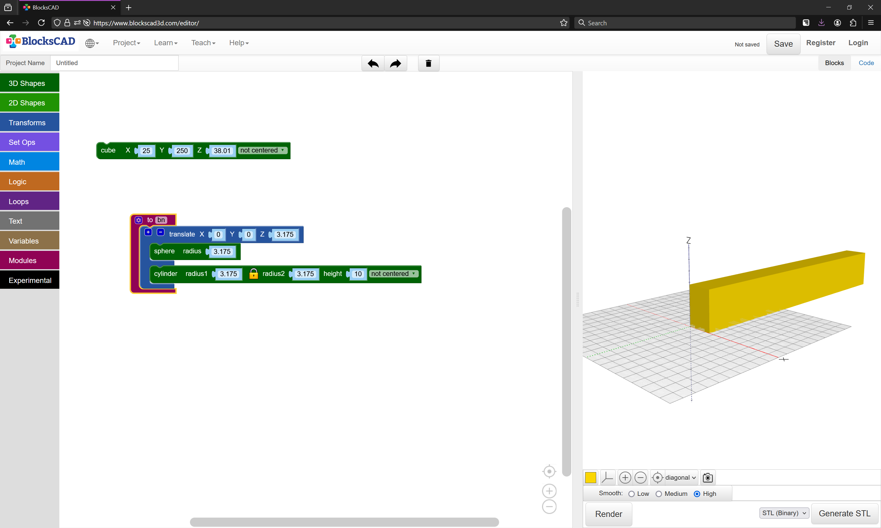
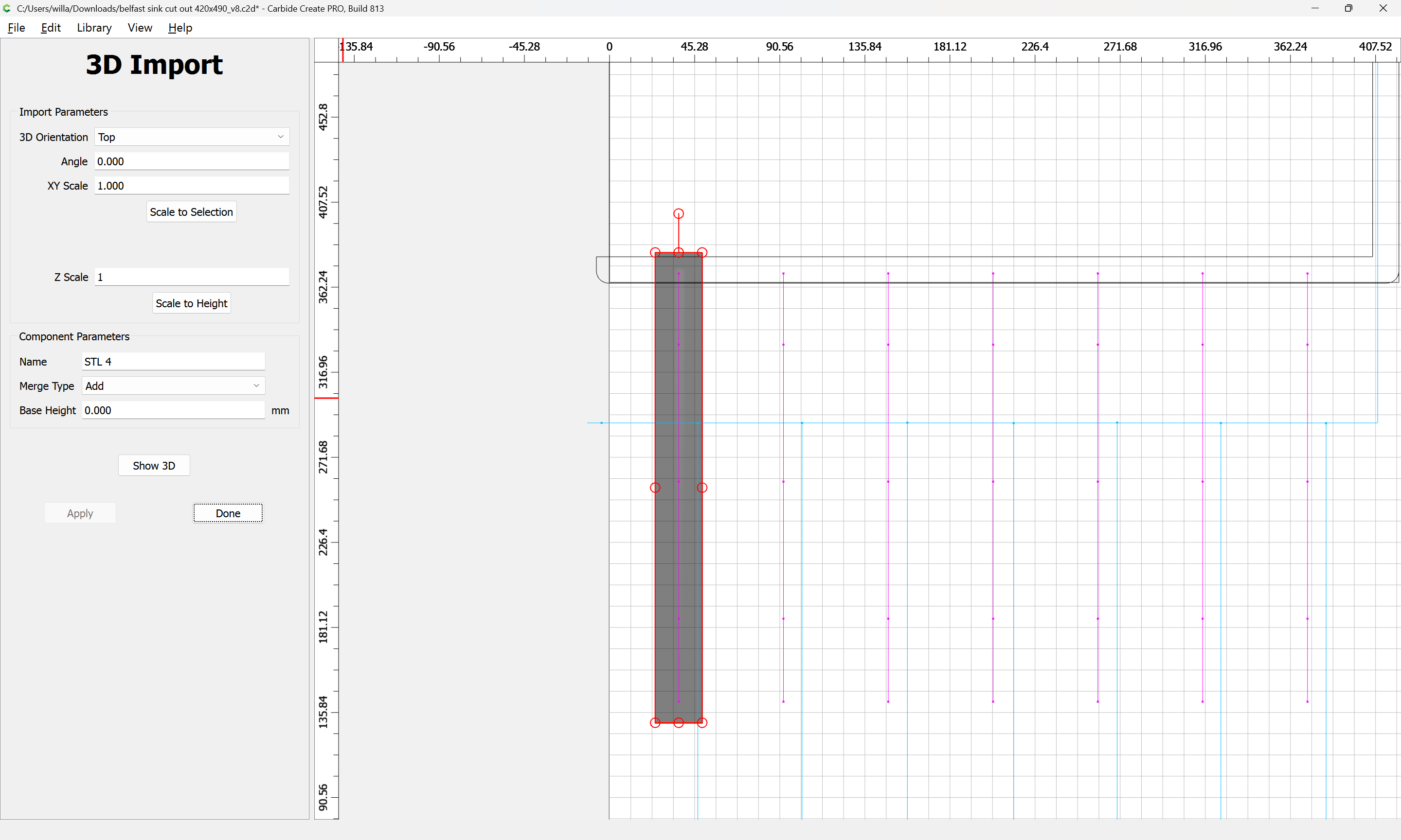
doing this in Carbide Create Pro is pretty straight-forward — draw up the stock around one groove:
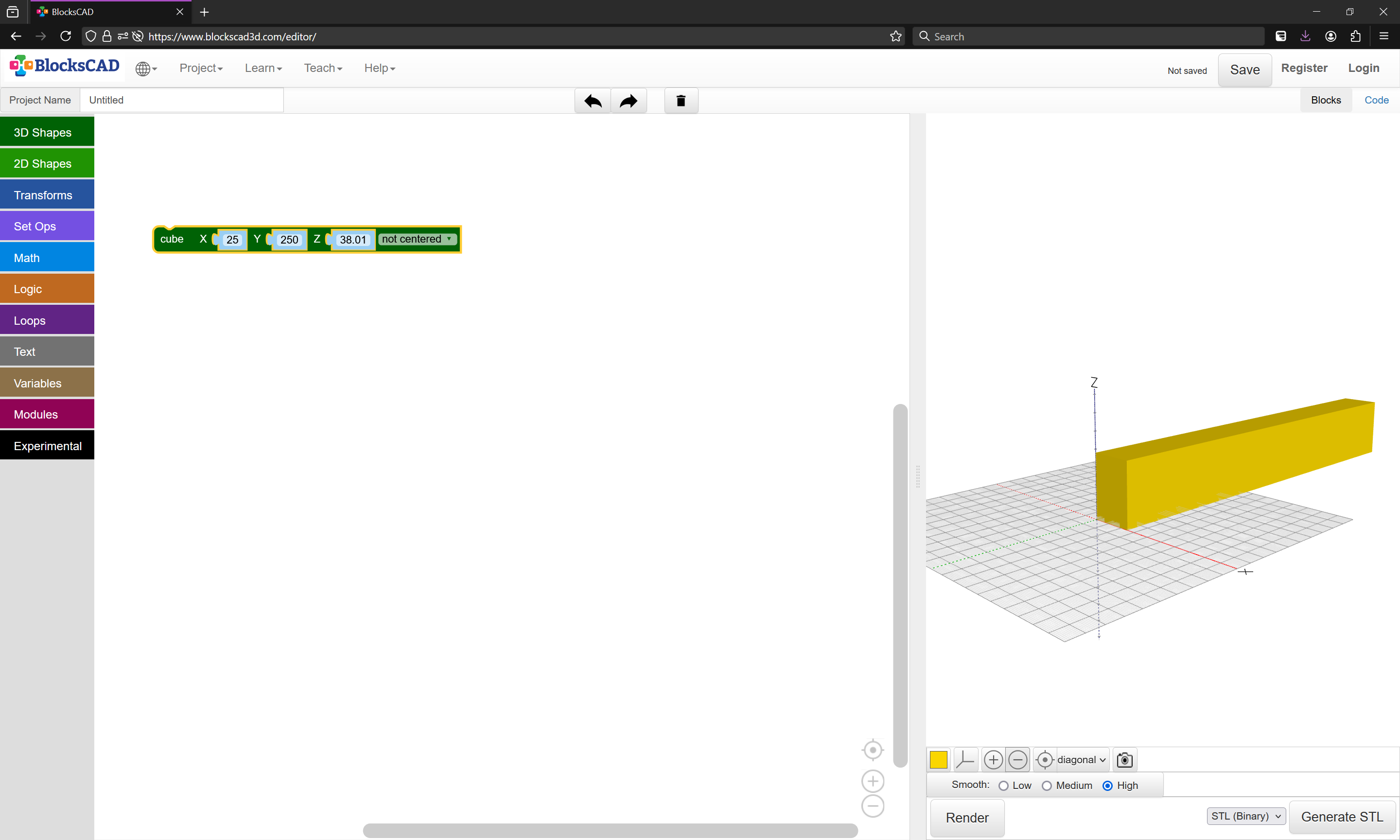
Model that in 3D:
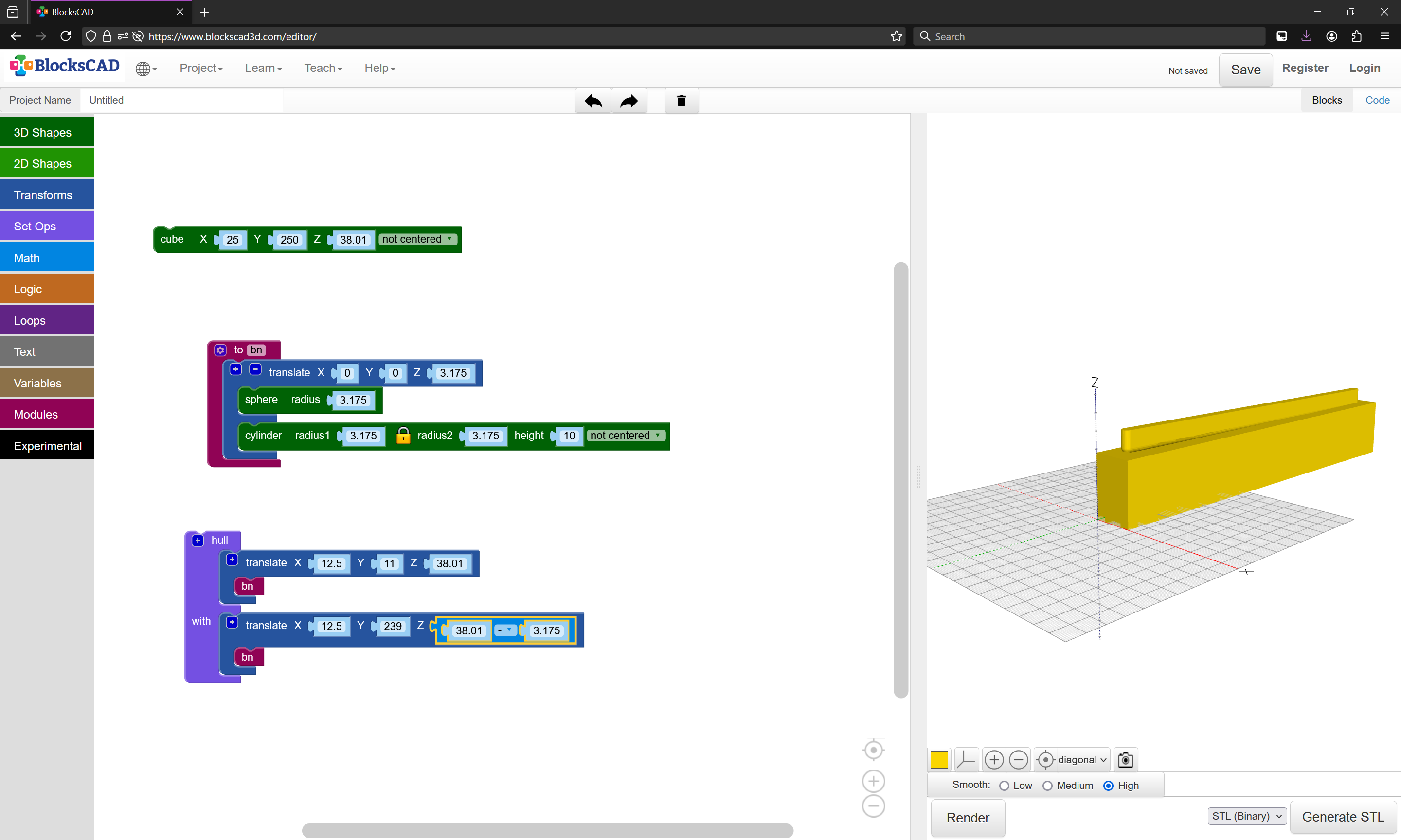
Then model the tool:
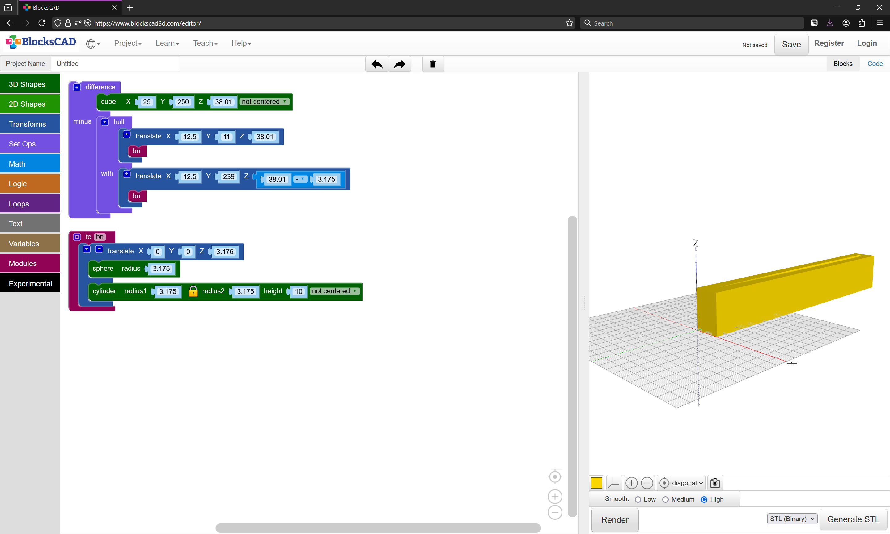
and use it in a Hull() operation to make the cutout:
which is Difference(d) from the stock:
Save as an STL:
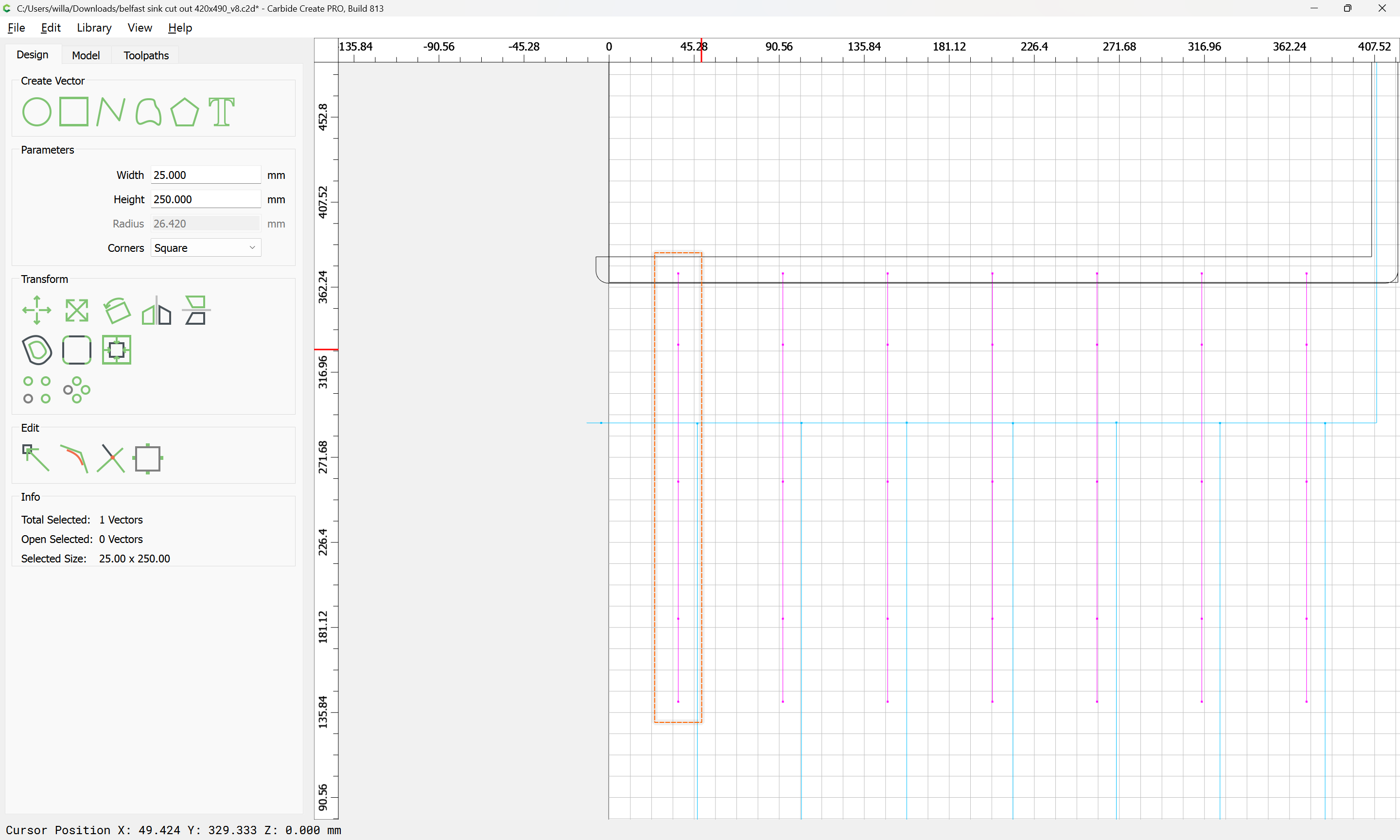
Then model it into the Carbide Create file:
Repeating for each groove, then assign 3D toolpaths as described at:
https://carbide3d.com/hub/courses/create-pro/
Or, use a traditional 3D tool such as Alibre:
or Fusion 360
Thankyou William.
I think i will get carbide pro and put it in that way, when i get it and try and put it in would you mind double checking it over for me?
Sounds like a plan!
Glad to try to help out!
Thankyou, i will let you know.
Hello William, me again!
I have downloaded Pro and had a go again at the sink cut out and drainer grooves.
Could you take a look at this for me please?
I have tried to do the 3d slope in sketch up and managed to import the stl file, in my thinking i was going to just set it as a ball mill bit and do a straight line.
I’m a bit stuck as how to plan the toolpaths for the grooves now, either as the image or by using the shapes options?
belfast cutout in create pro.c2d (76 KB)
Unfortunately, CC can’t do a contour cut following a 3D shape. (Yet! ![]() )
)
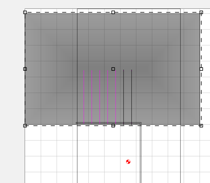
But you can limit the extent of the 3D finish path using a really skinny boundary. You have your groove modeled at about 6.7mm wide, and using a 1/4" tool (6.35mm), if you make a boundary 6.7 - 6.35 (0.35mm) wide, and the length of the groove, with a very small stepover [0.1 - 0.2mm], and cut at 90°, you get a path like this…
You don’t need to model the groove as a groove, just a tapered surface.
Thankyou, i can’t seem to get to the settings you show there William?