as requested on support…
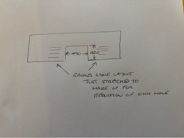
Given a rough sketch:
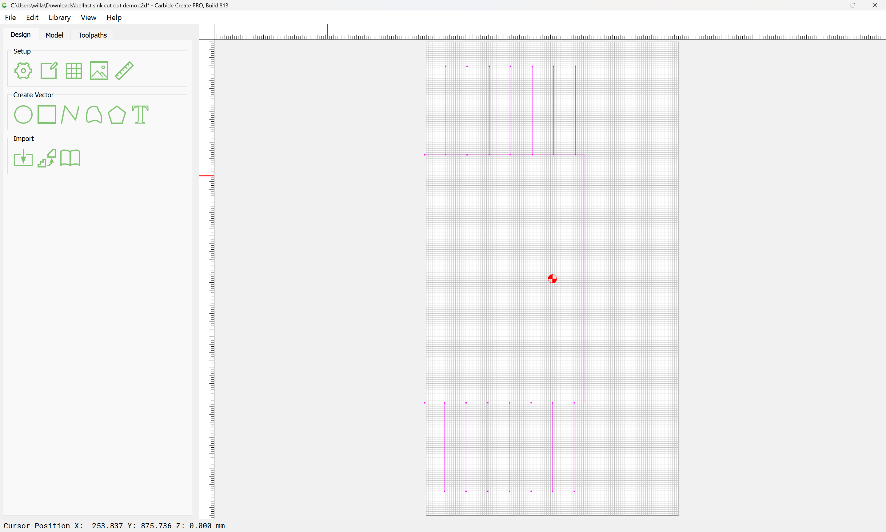
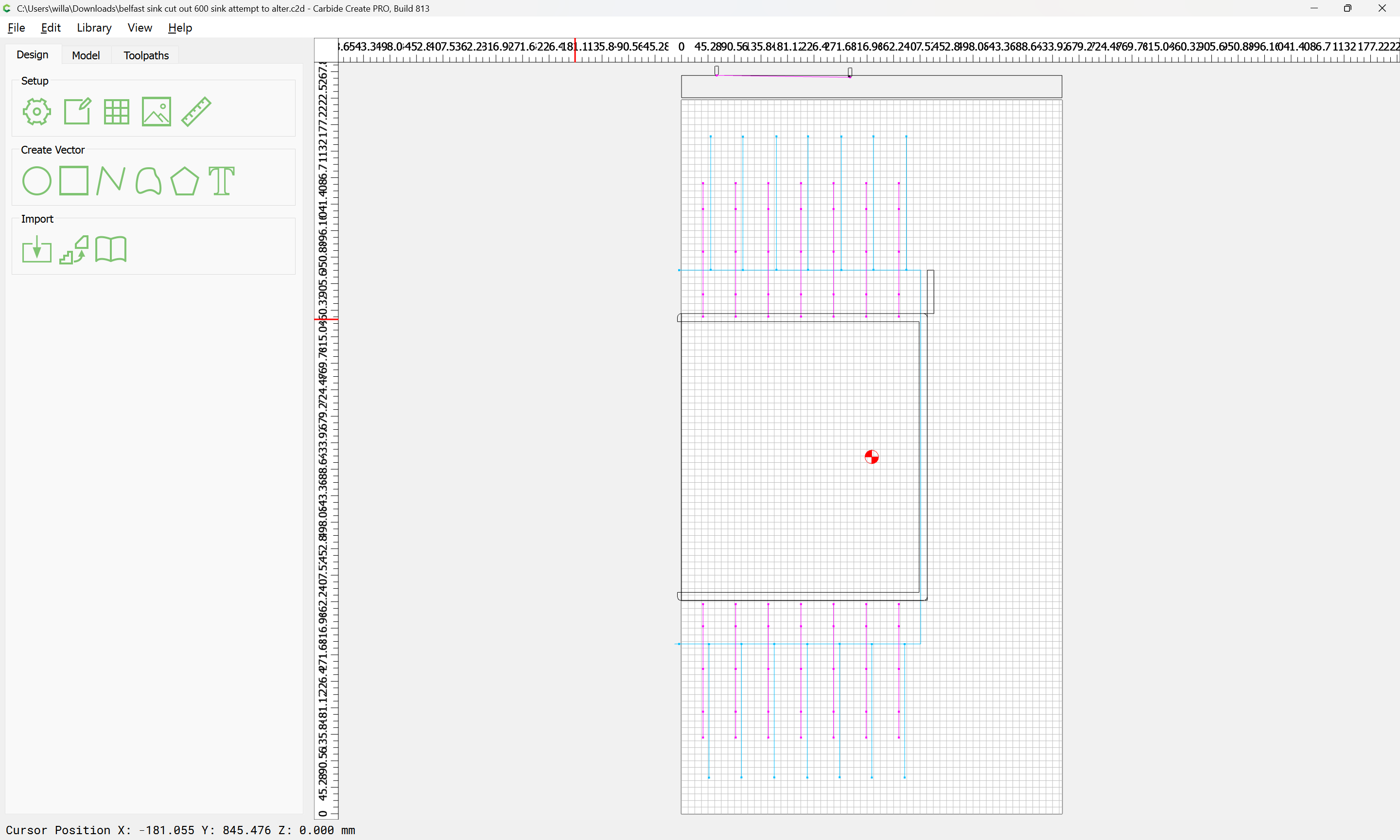
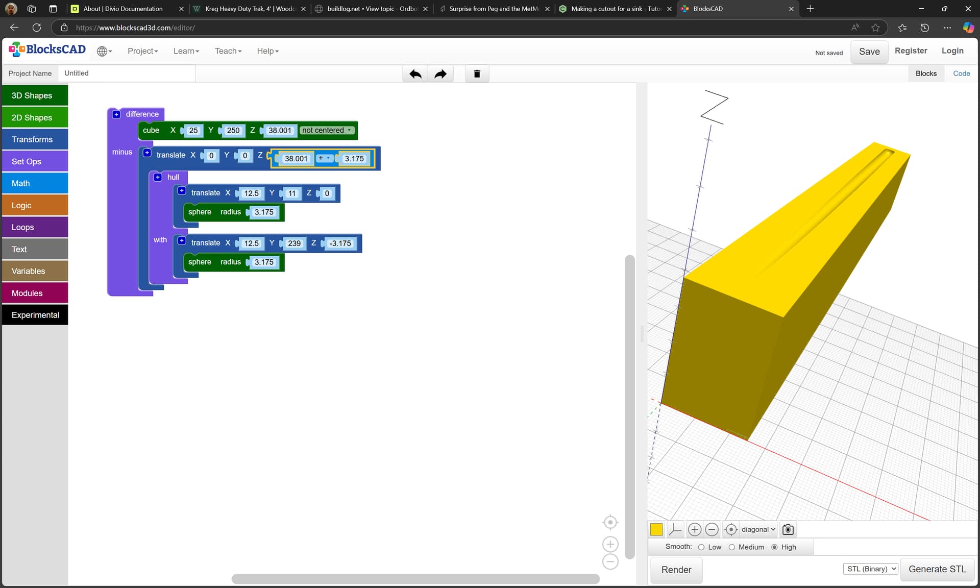
The goal is to make grooves using a 1/4" ball-nose (vertical lines), and a cutout for a farmer-style sink (the rectangle missing the left side)
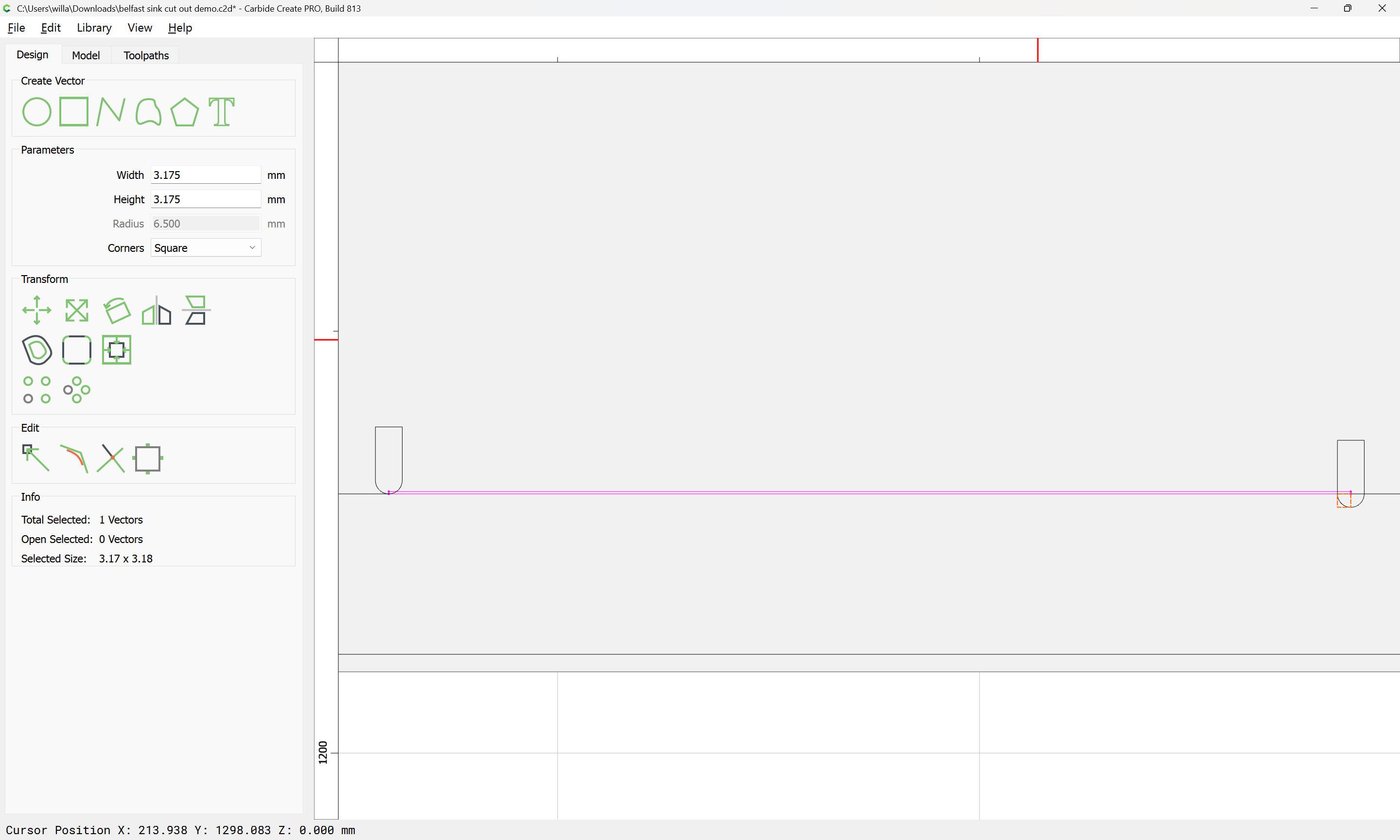
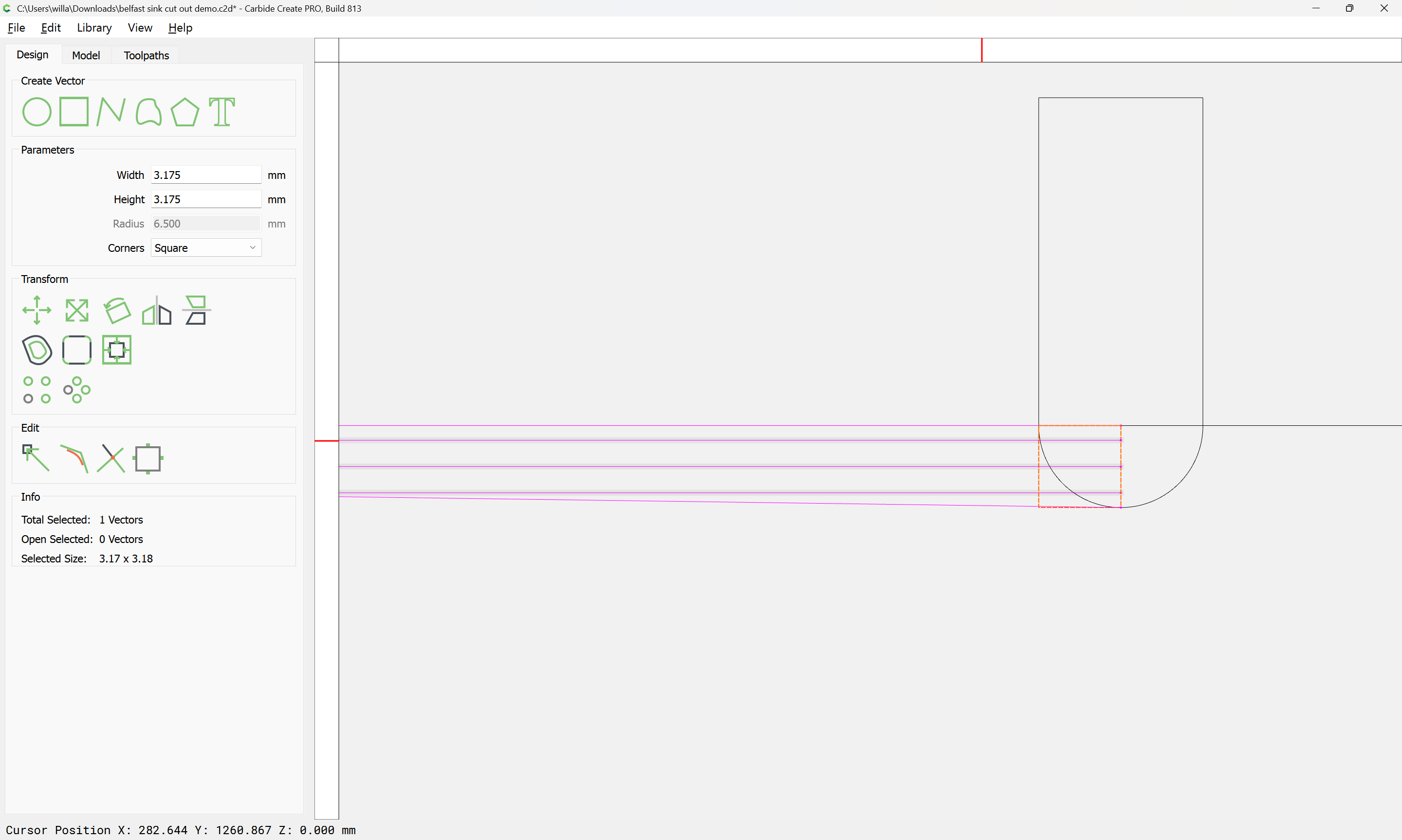
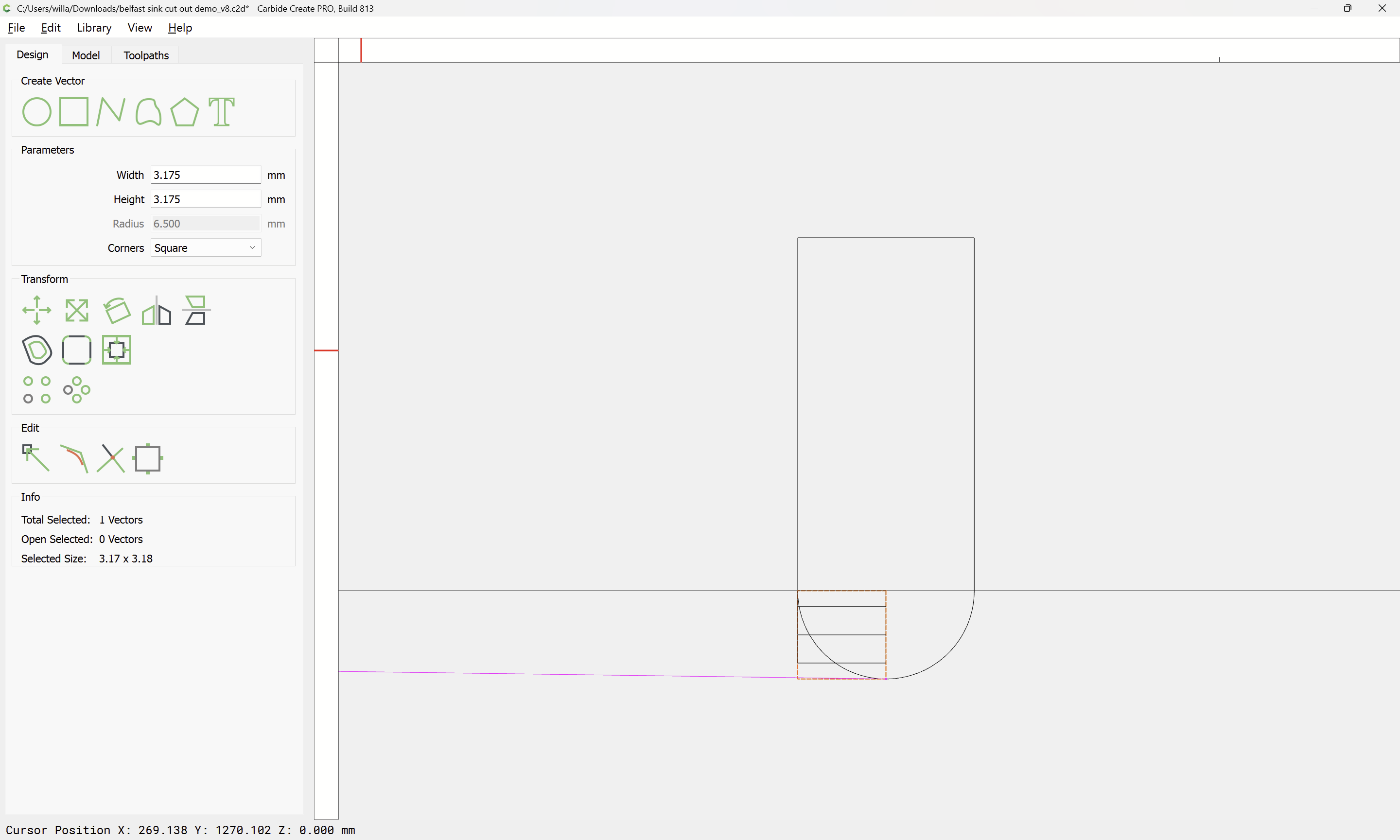
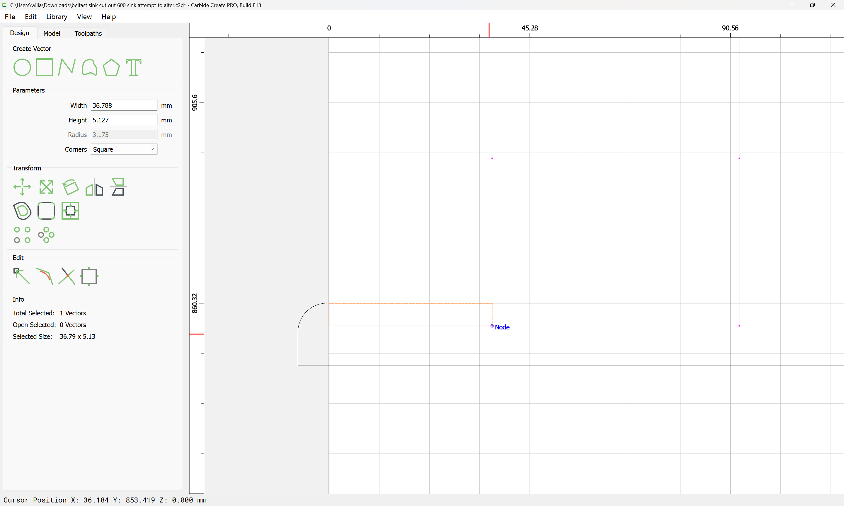
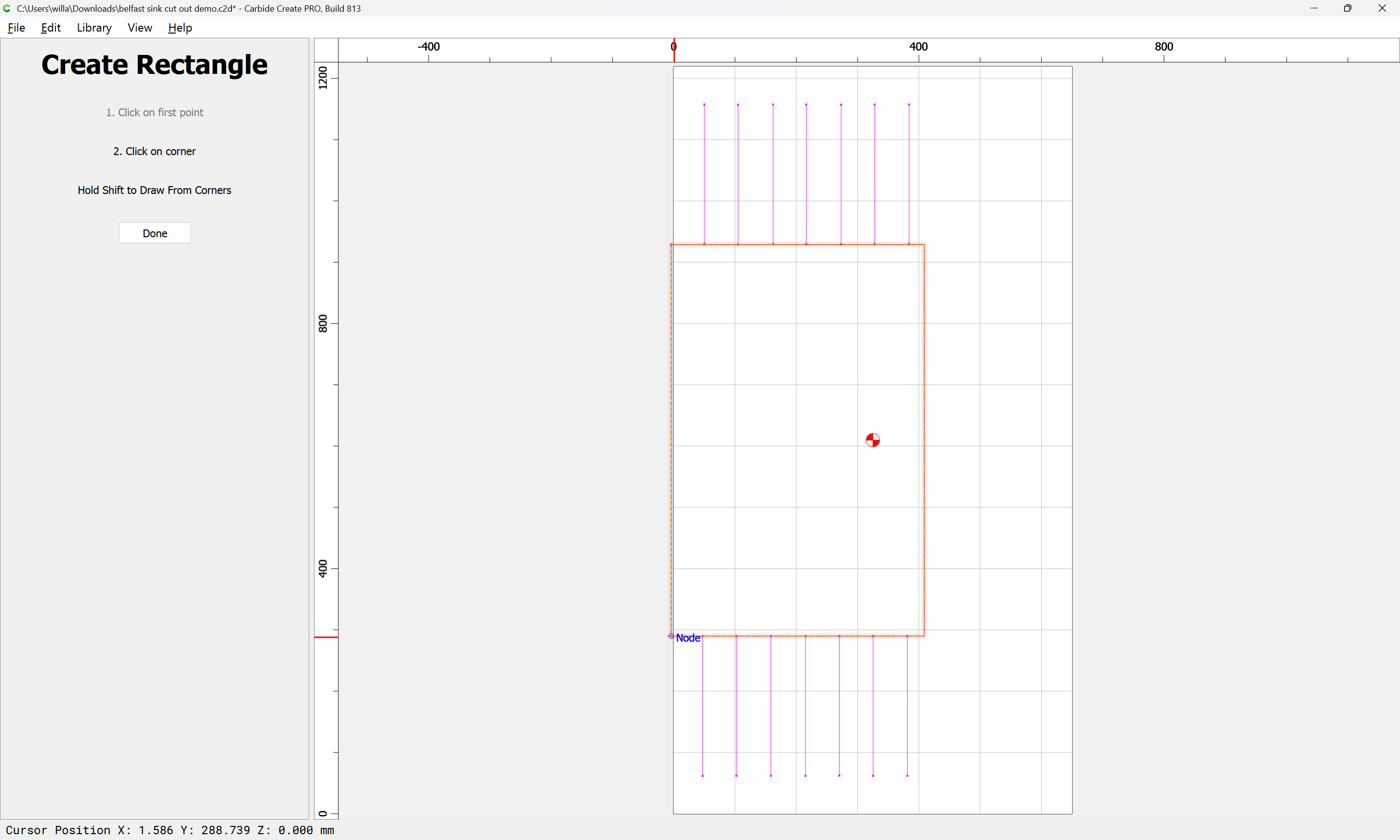
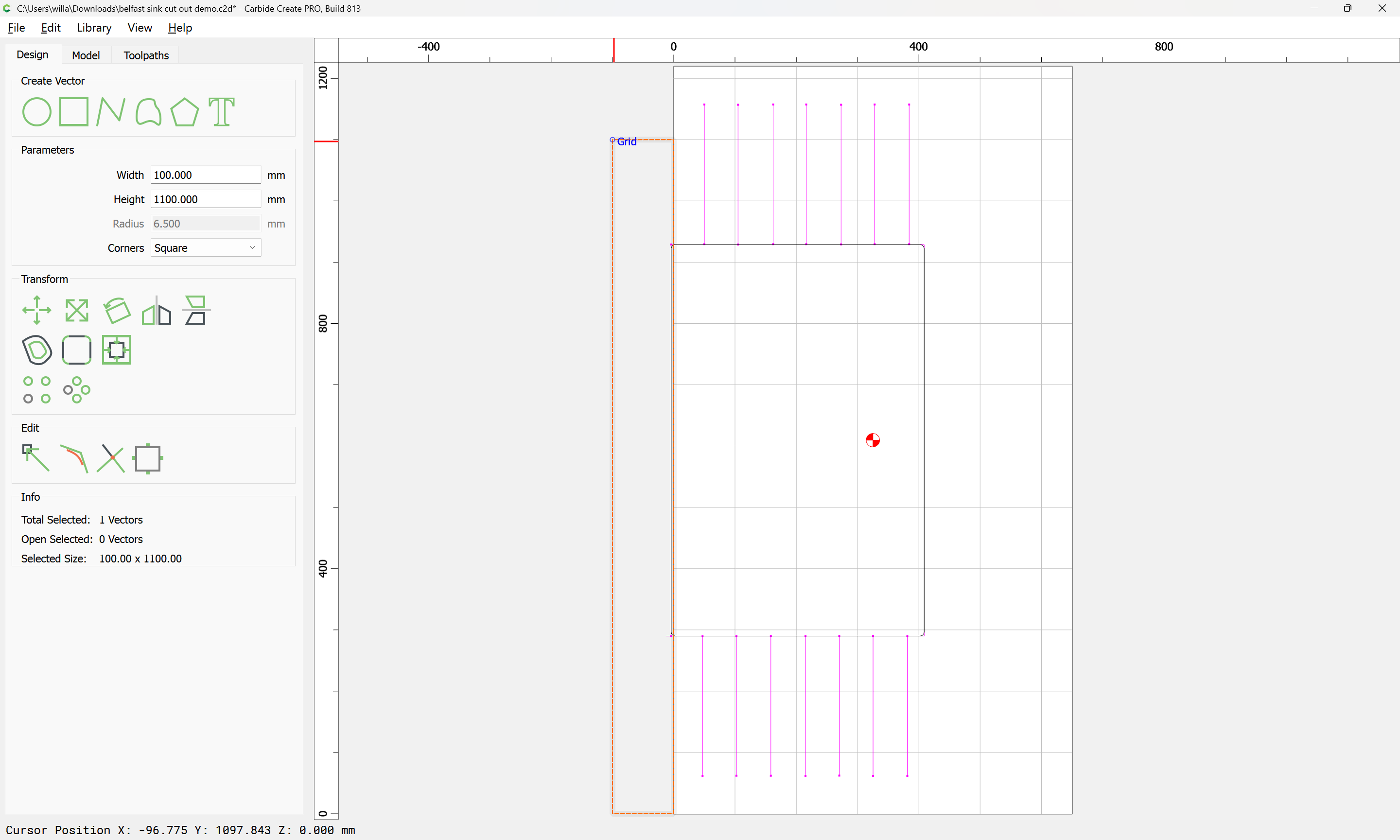
Since the cutout is easiest, we do that first — begin by drawing a rectangle:
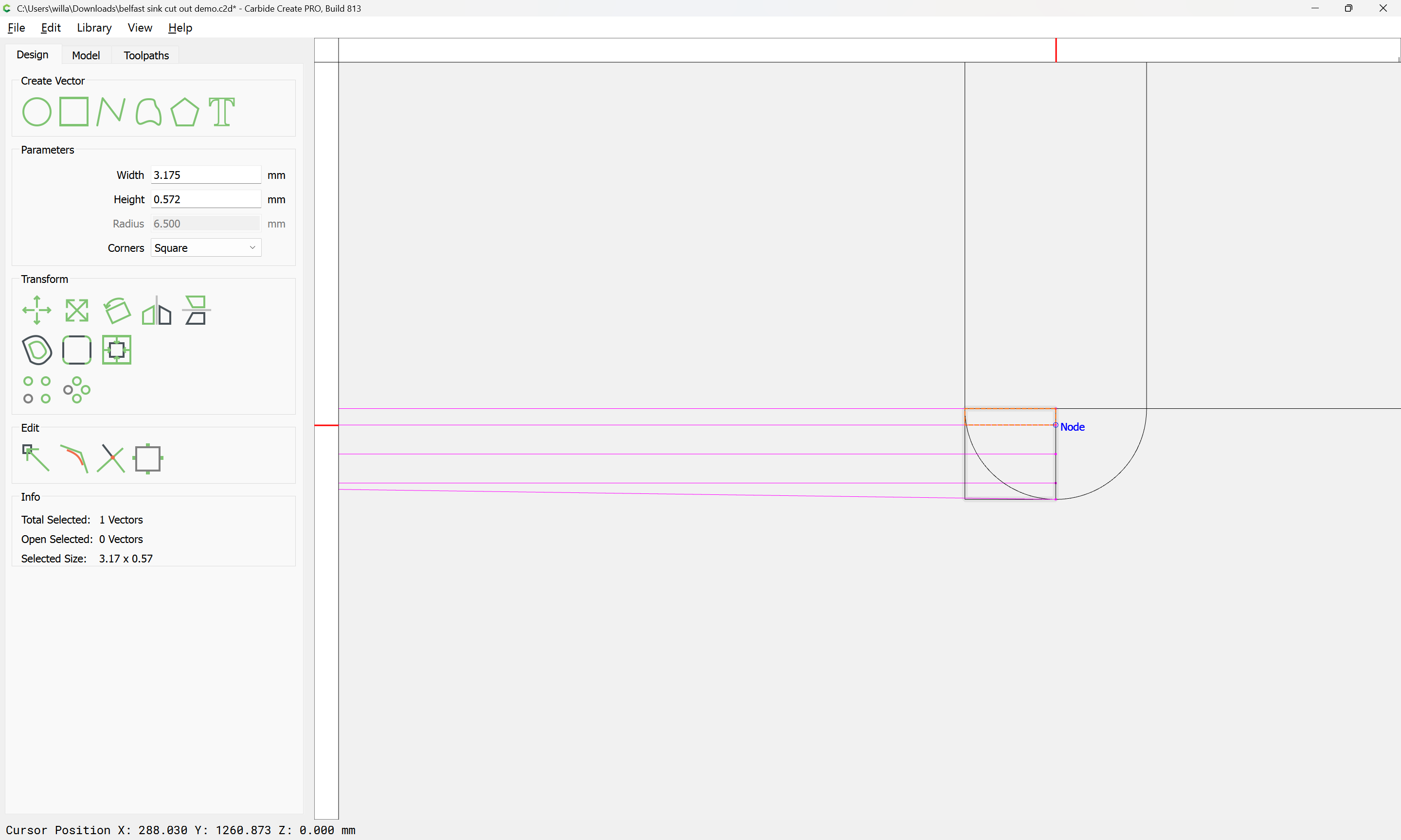
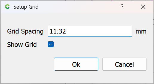
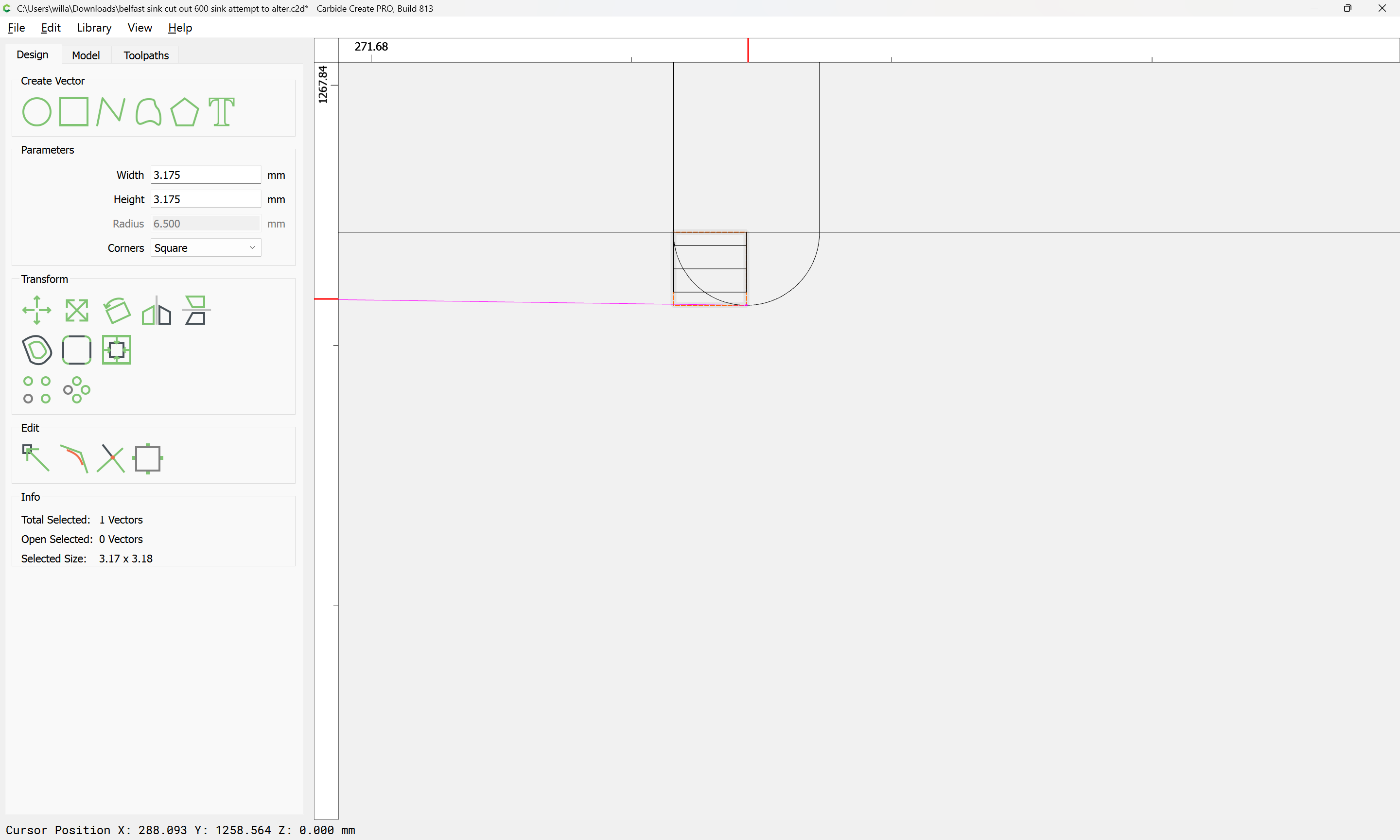
and adjusting it to have a radius greater than the 1/2" diameter tool envisioned for making this cut:
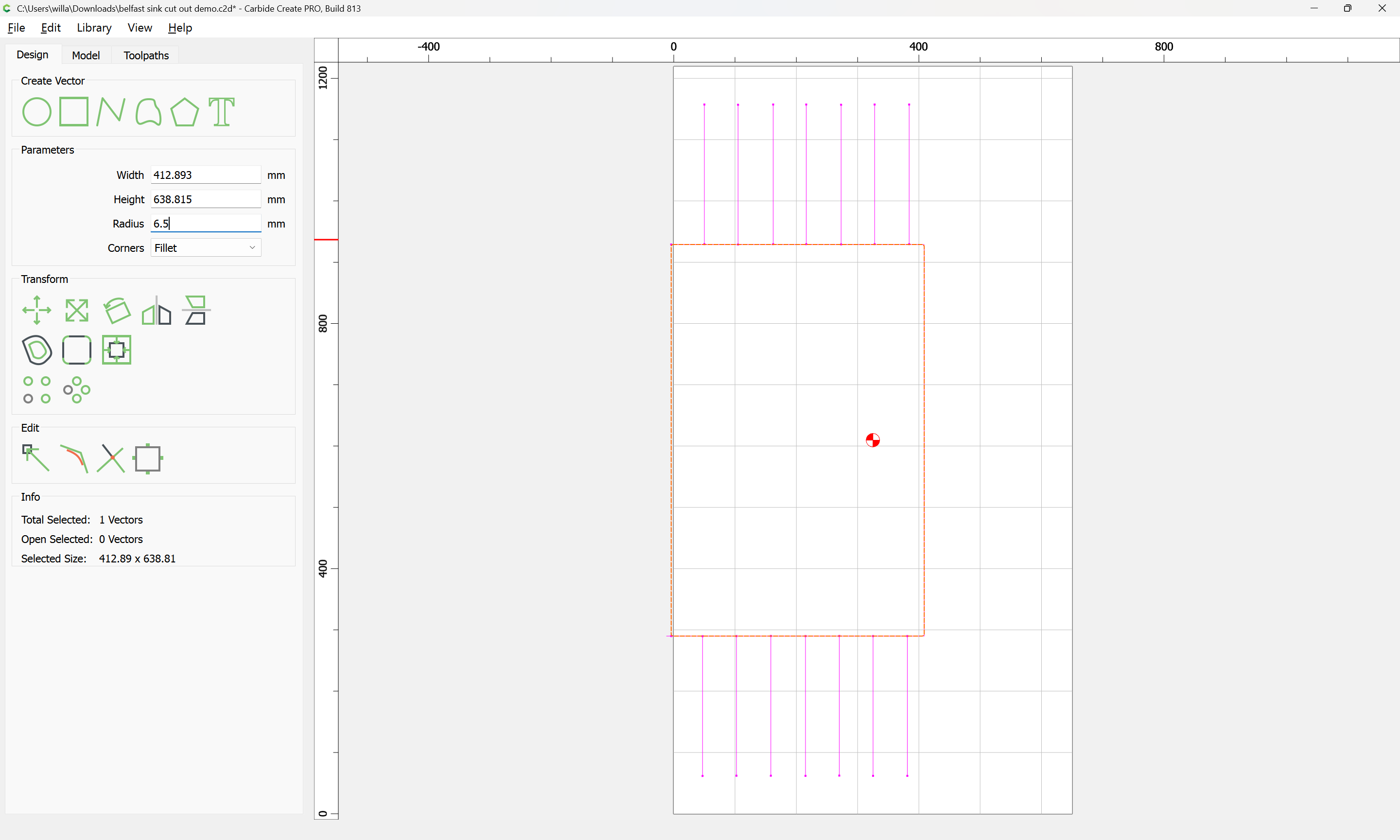
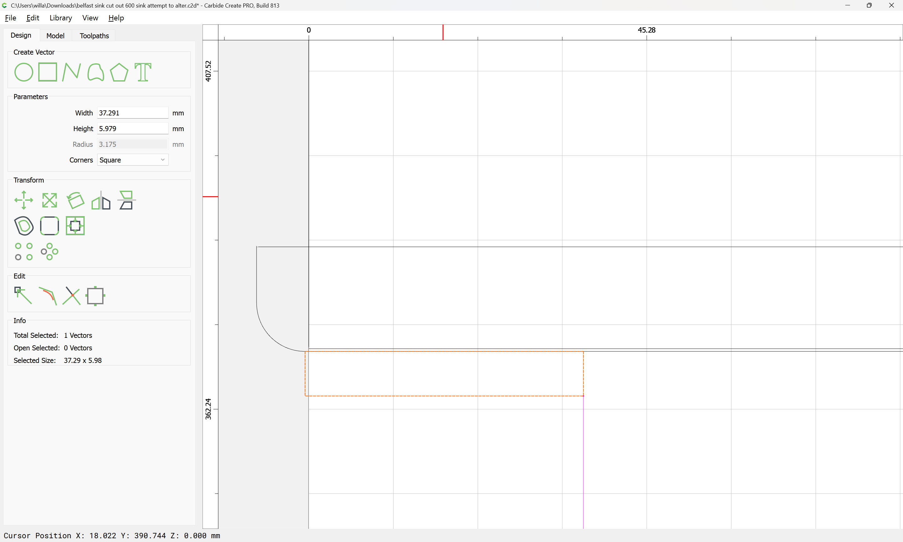
It is also necessary to ensure that it projects by a bit more than tool radius beyond the stock origin to the left:
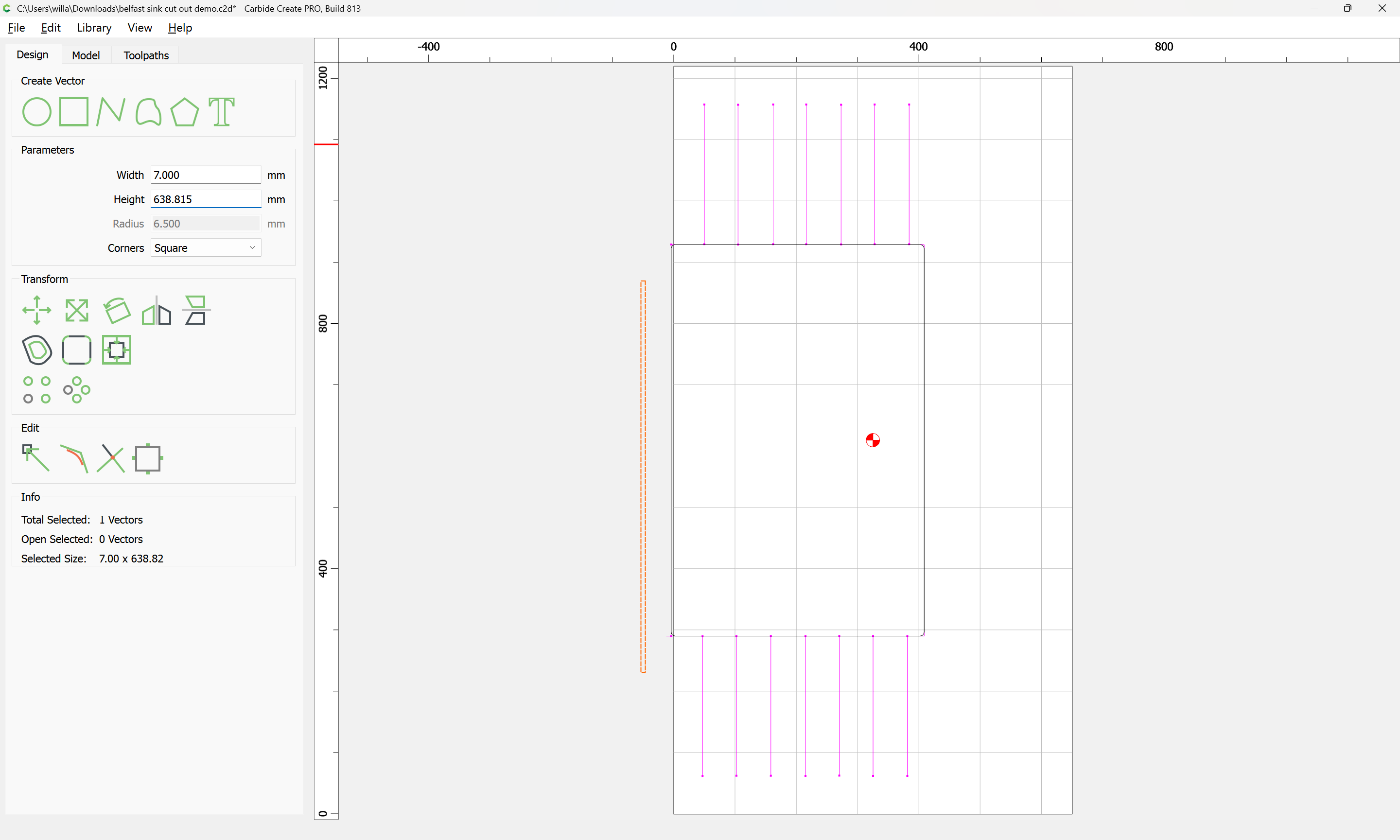

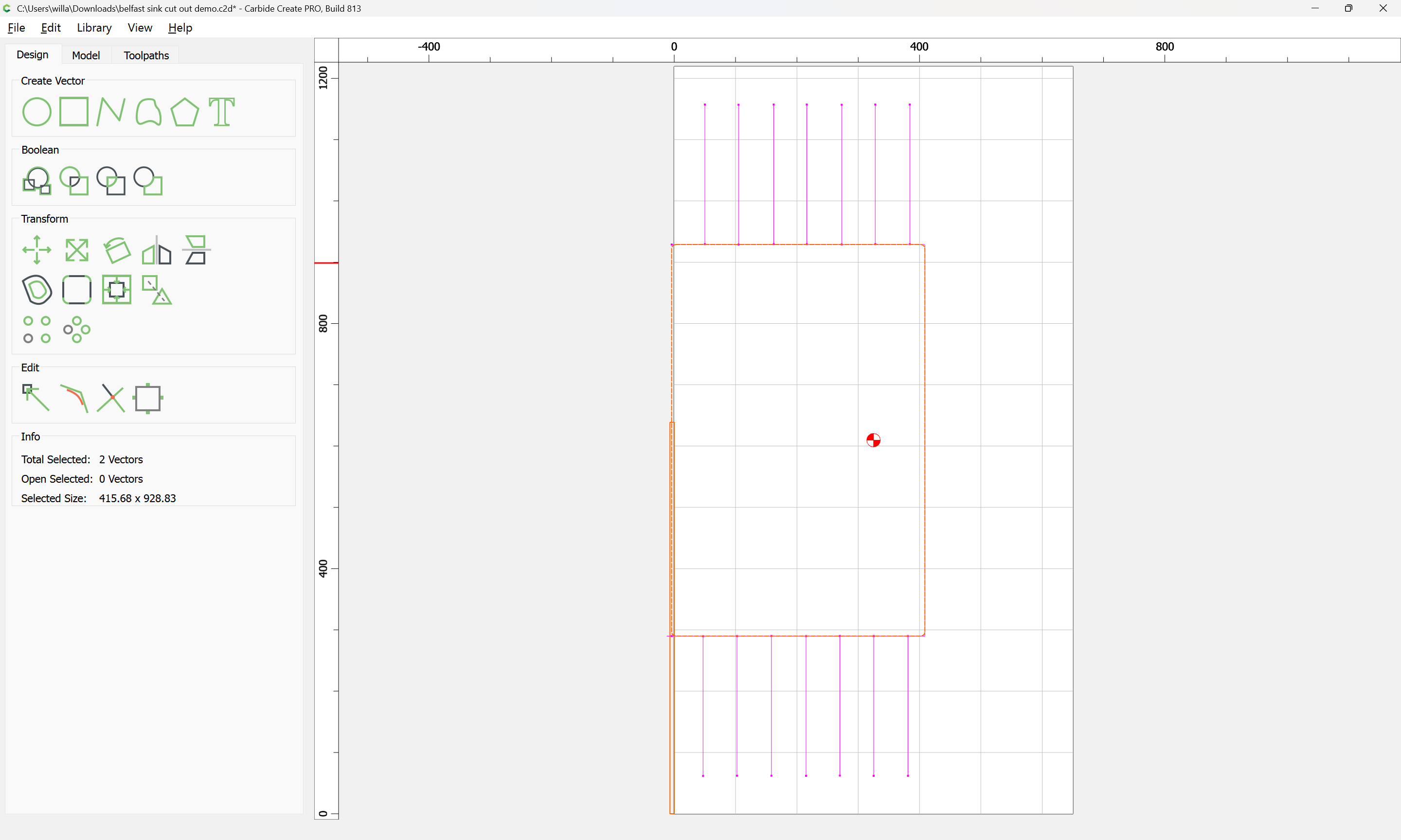
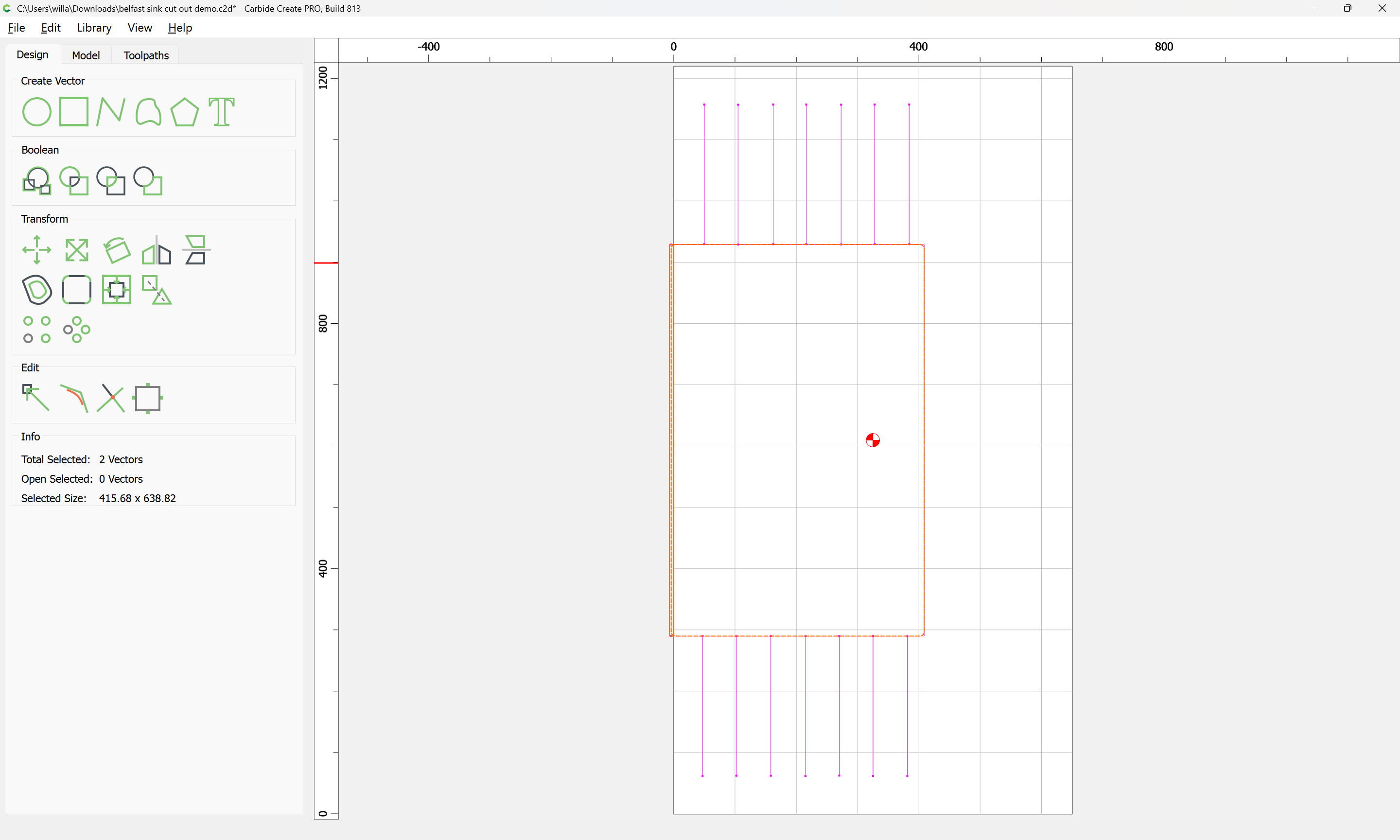
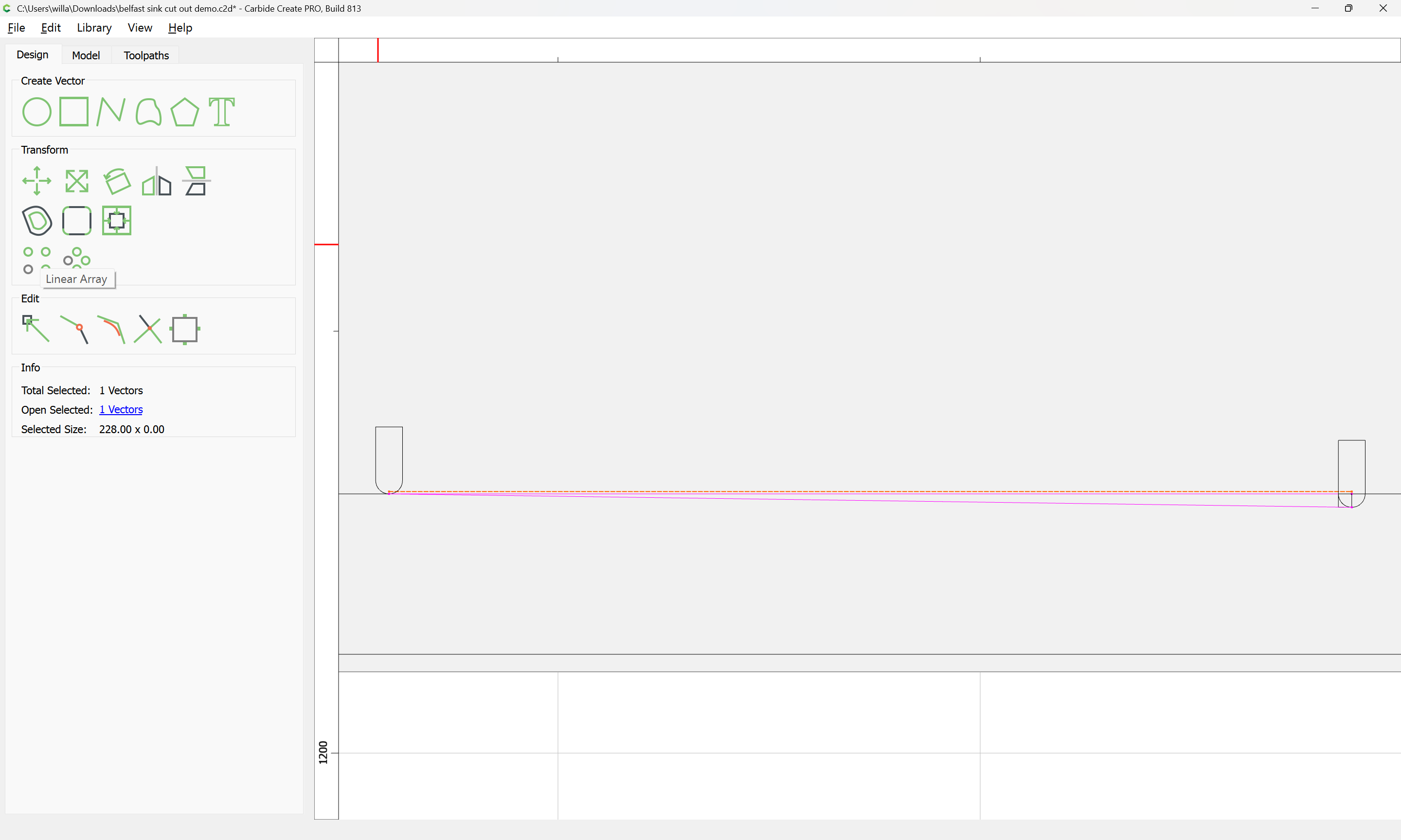
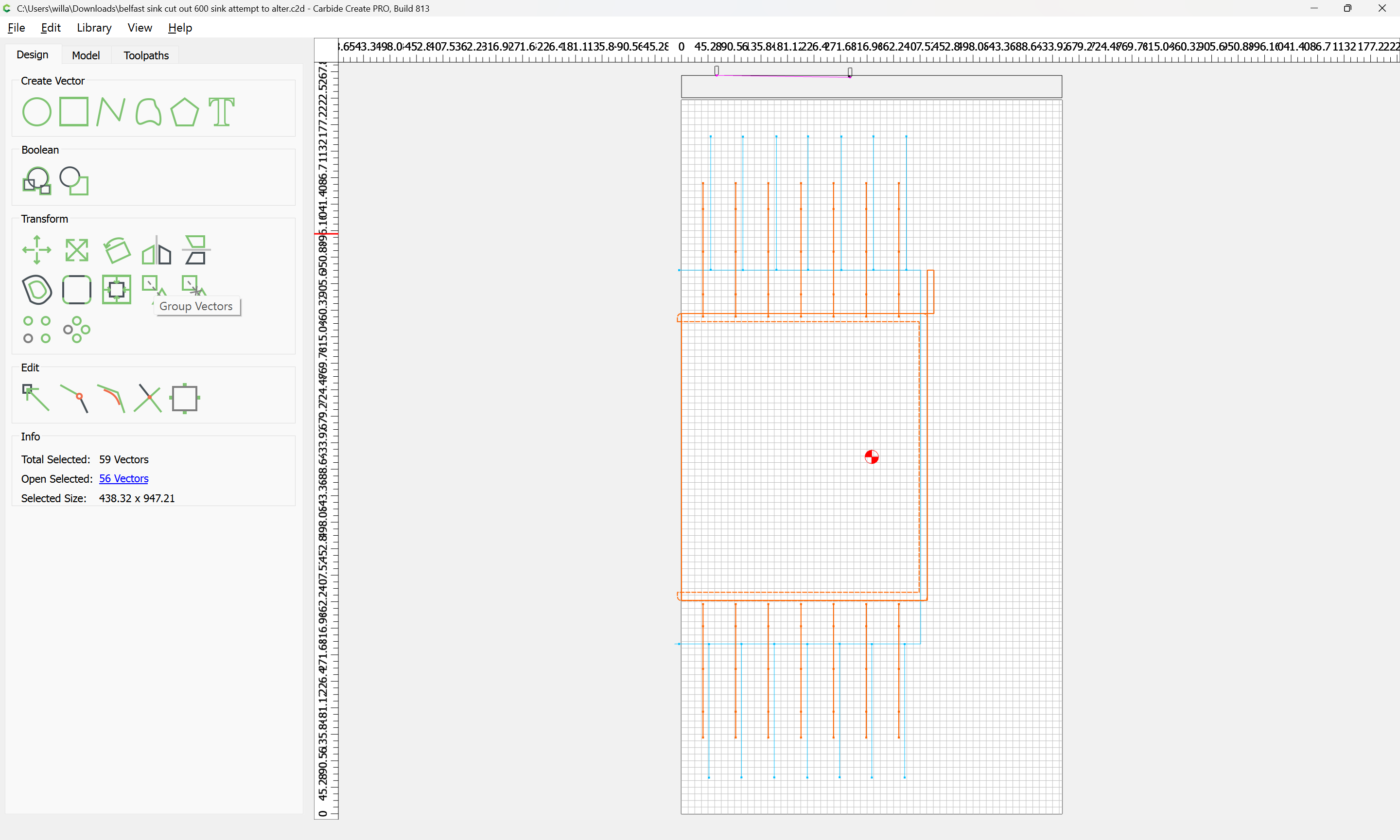
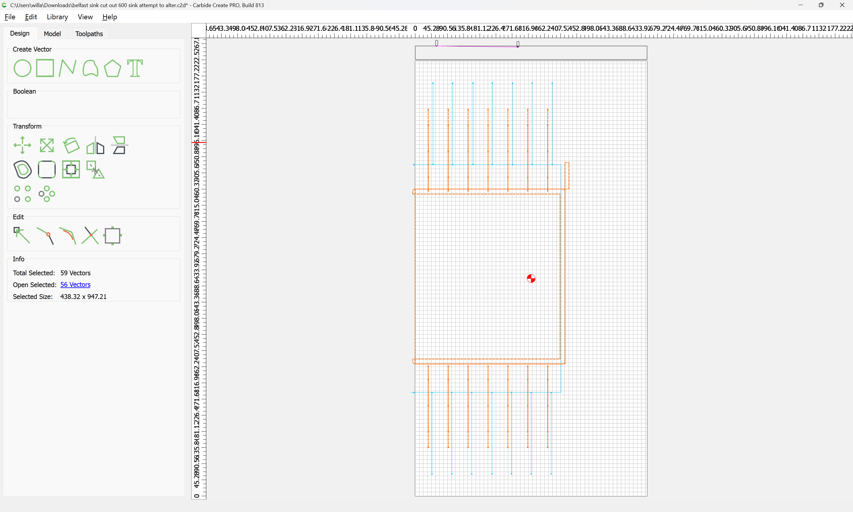
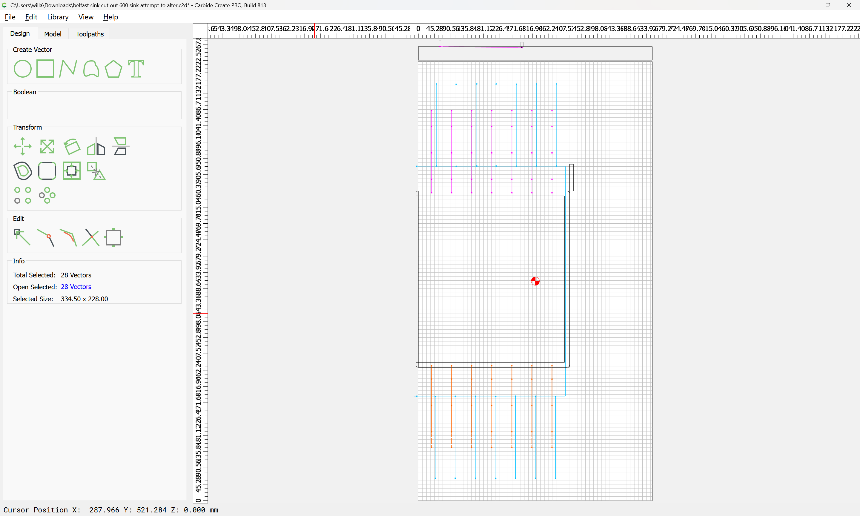
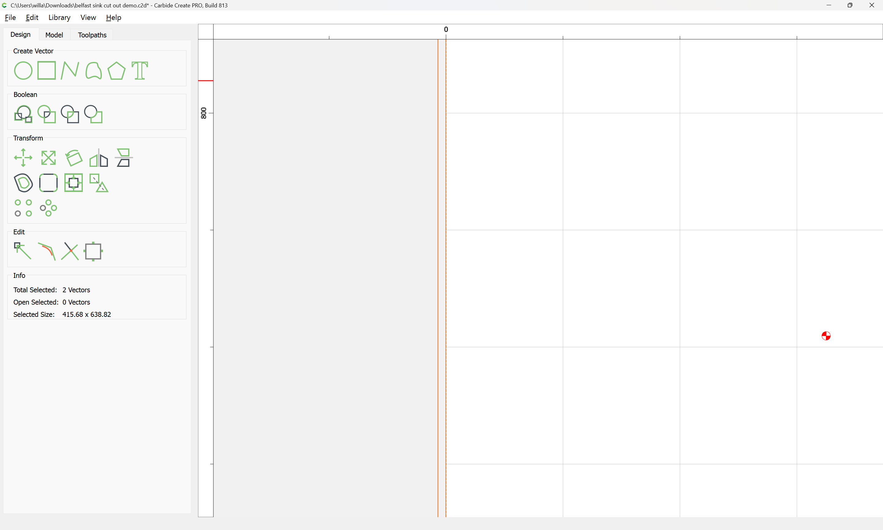
Note the width dimension for the selection, 415.68:
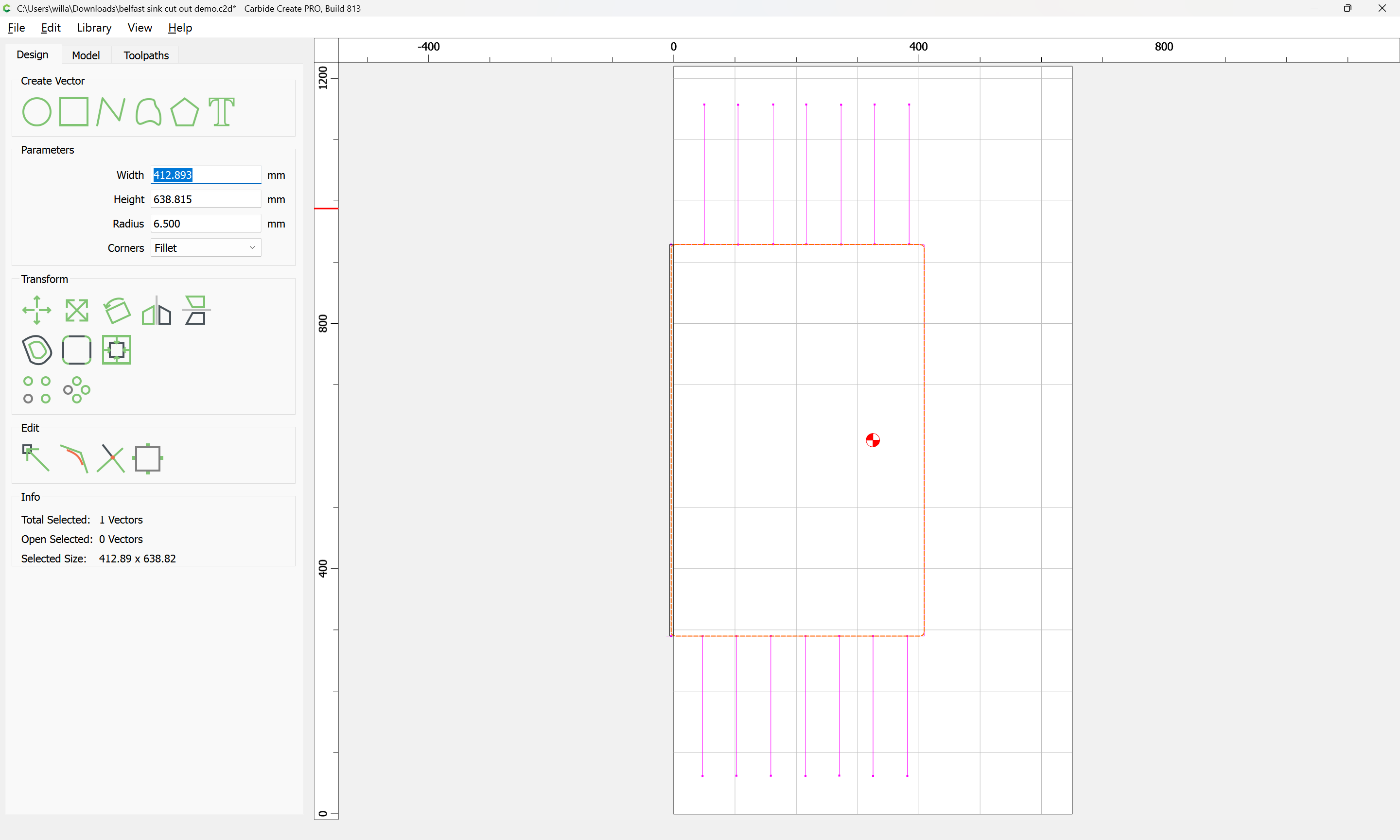
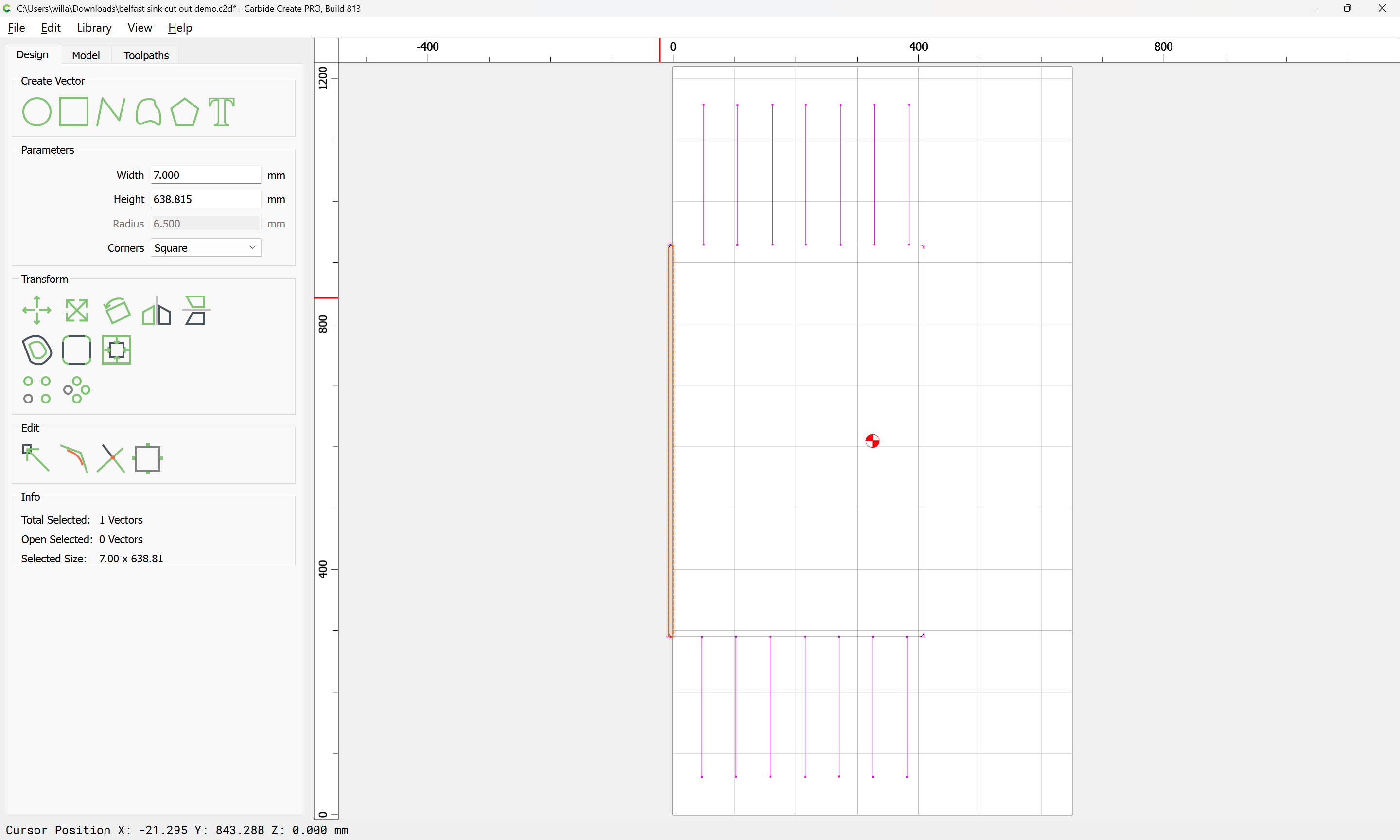
and change the original rectangle to that width:

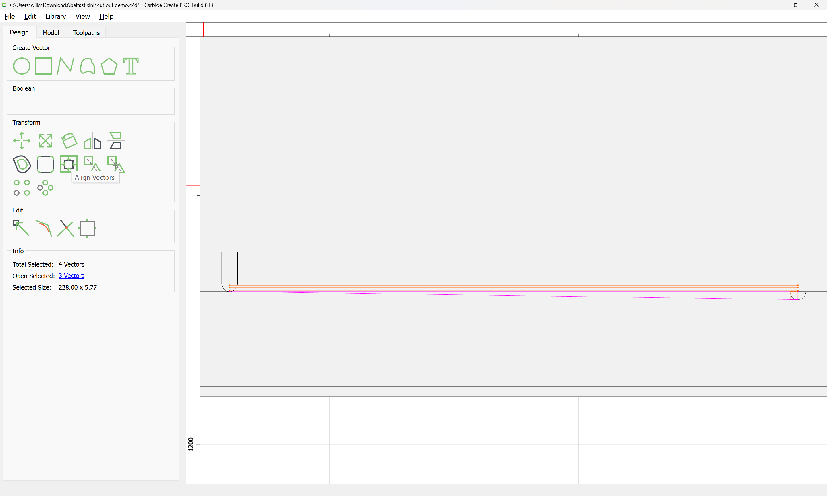
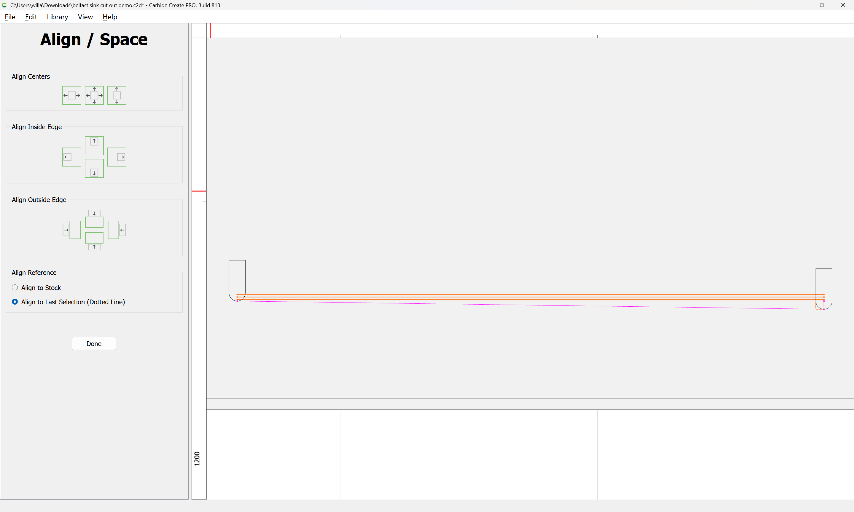
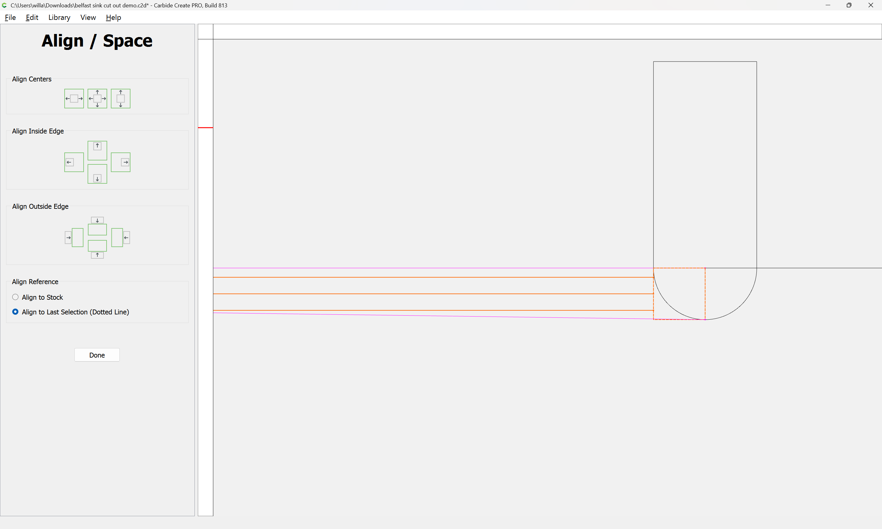
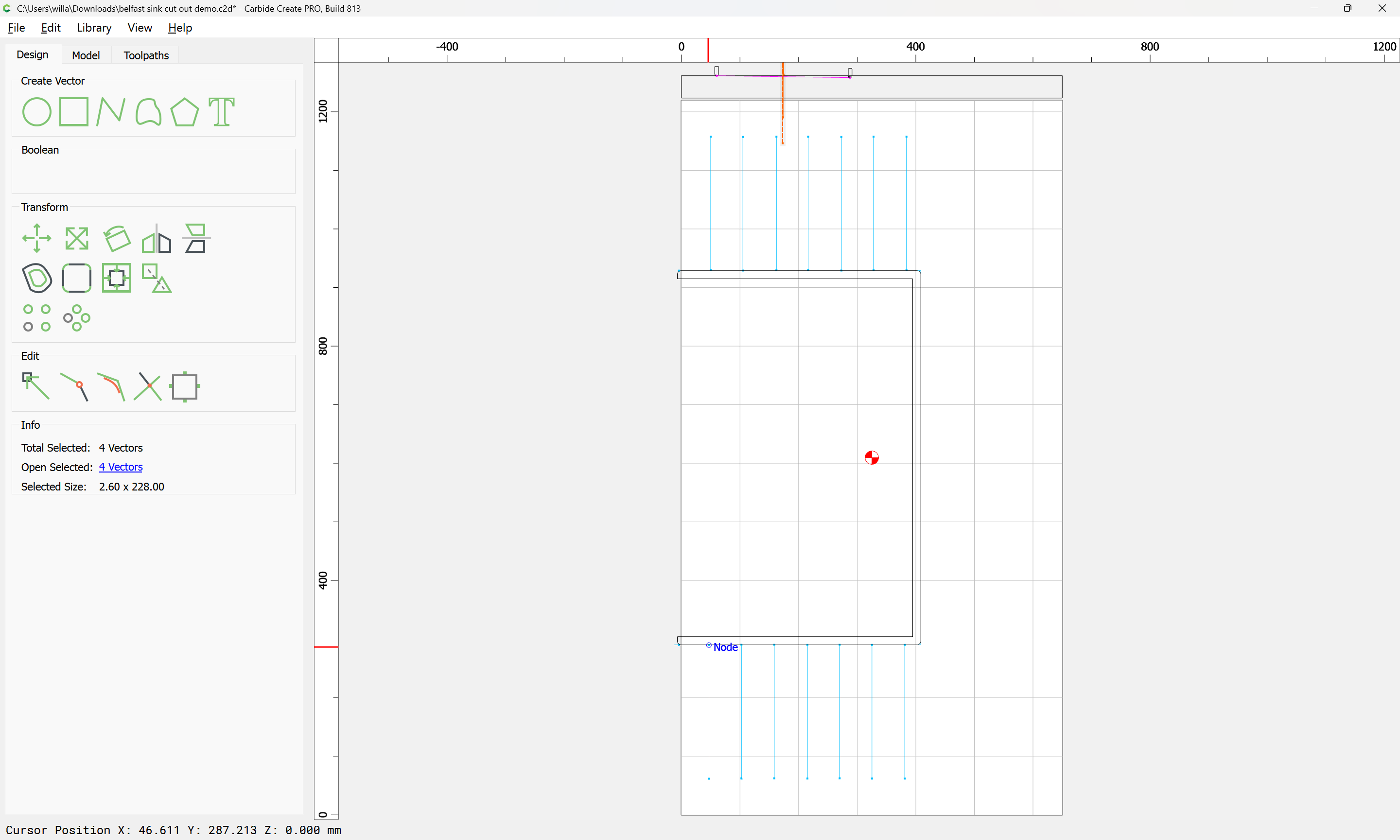
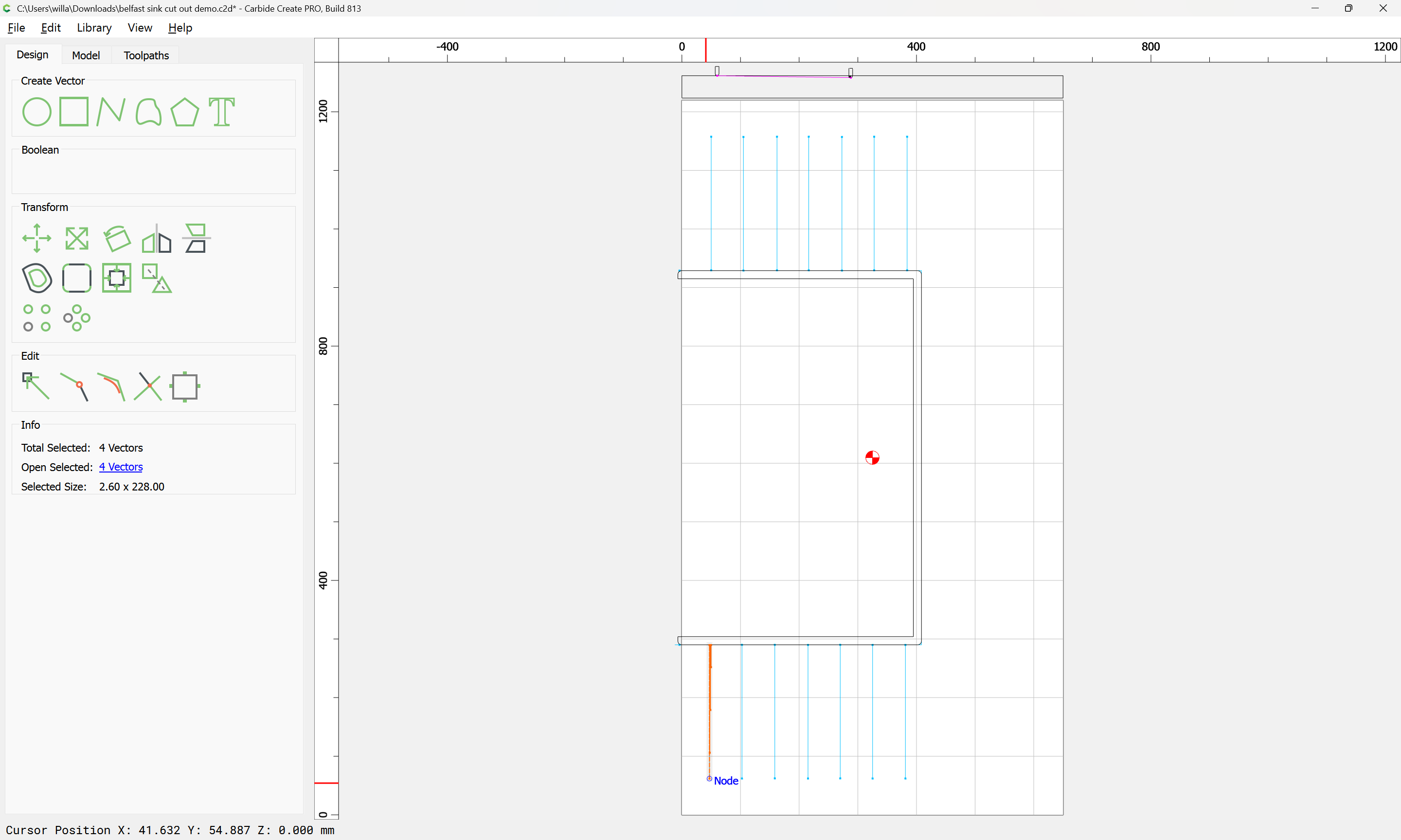
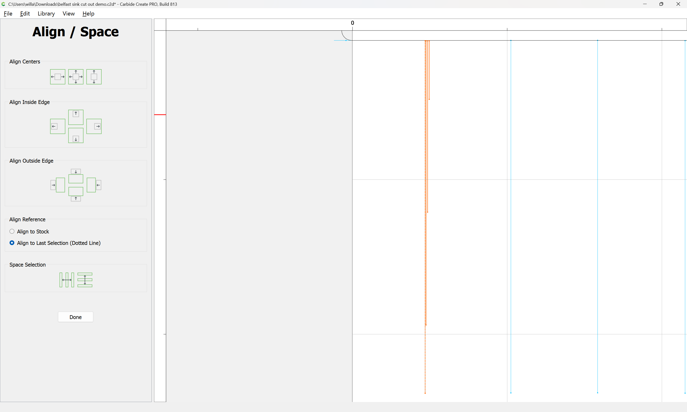
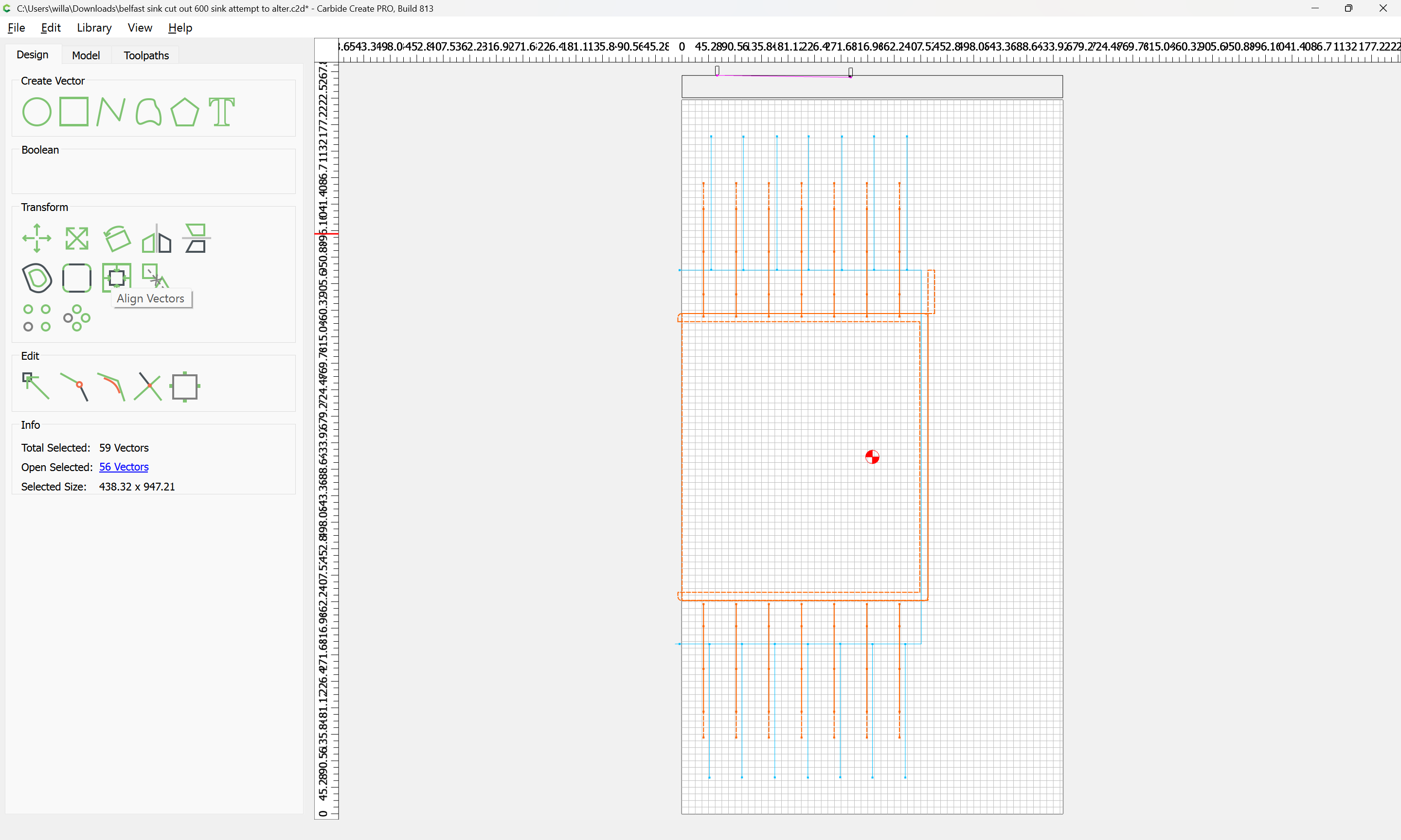
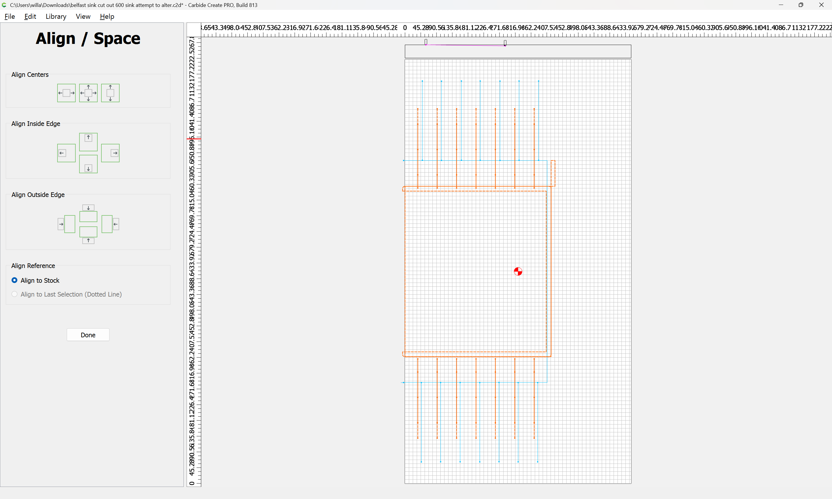
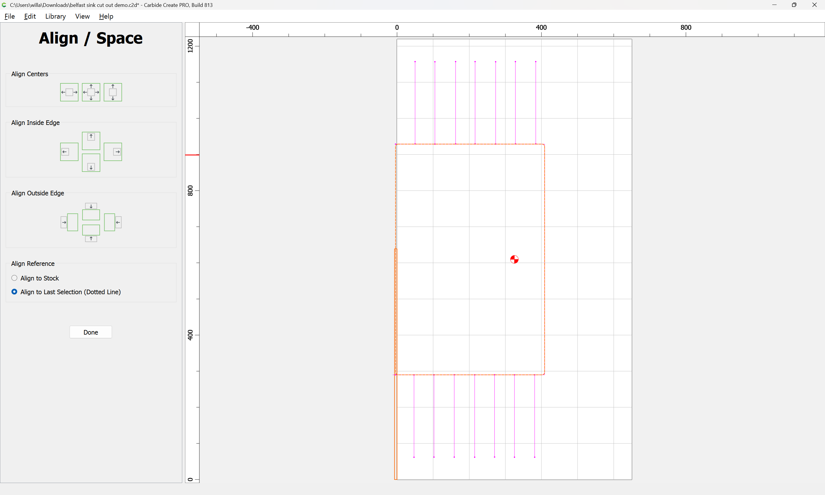
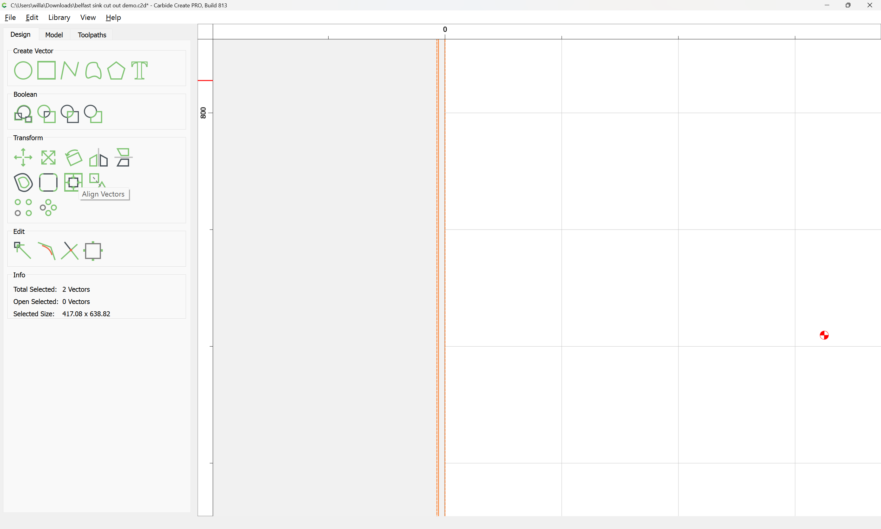
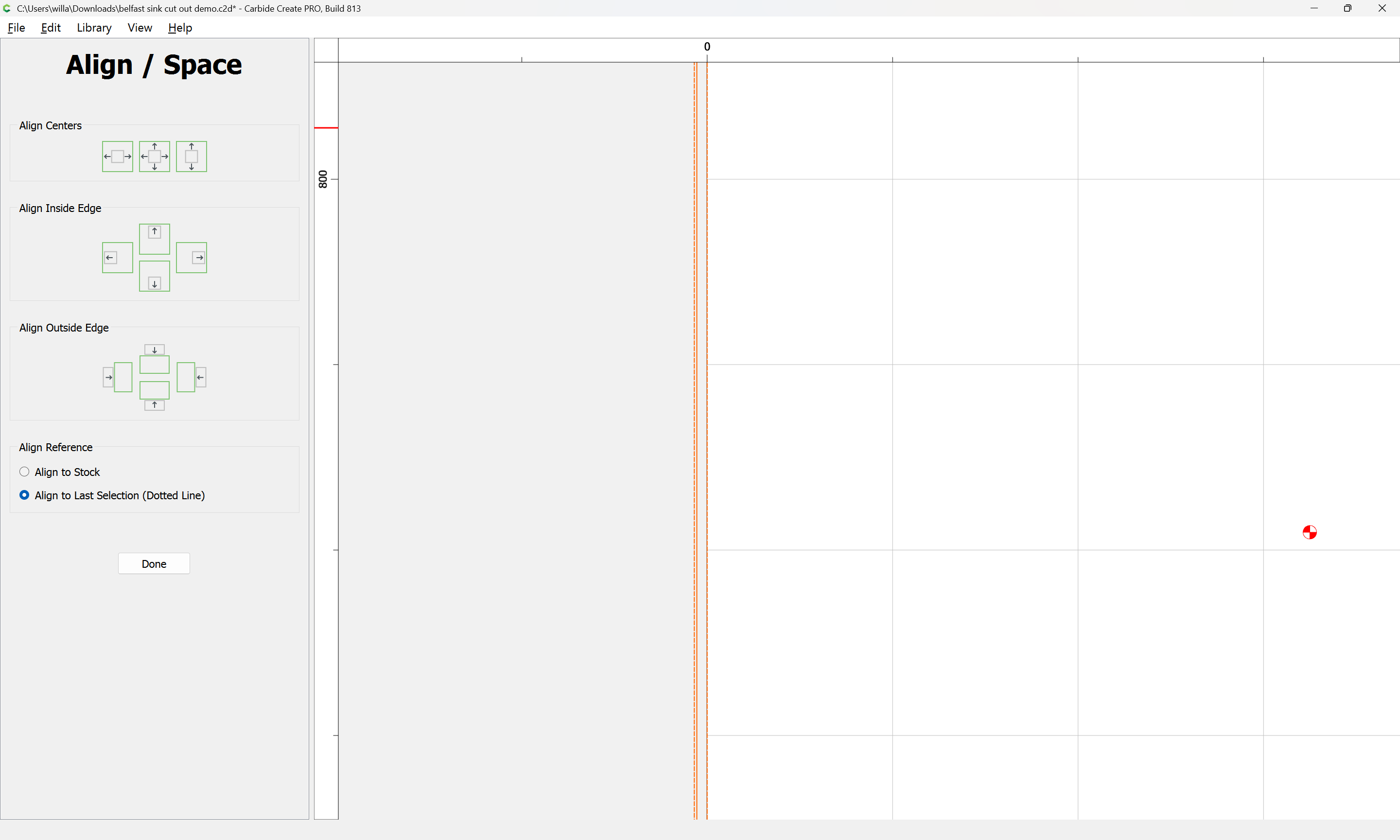
and then align it against the narrow one used to set the radius:
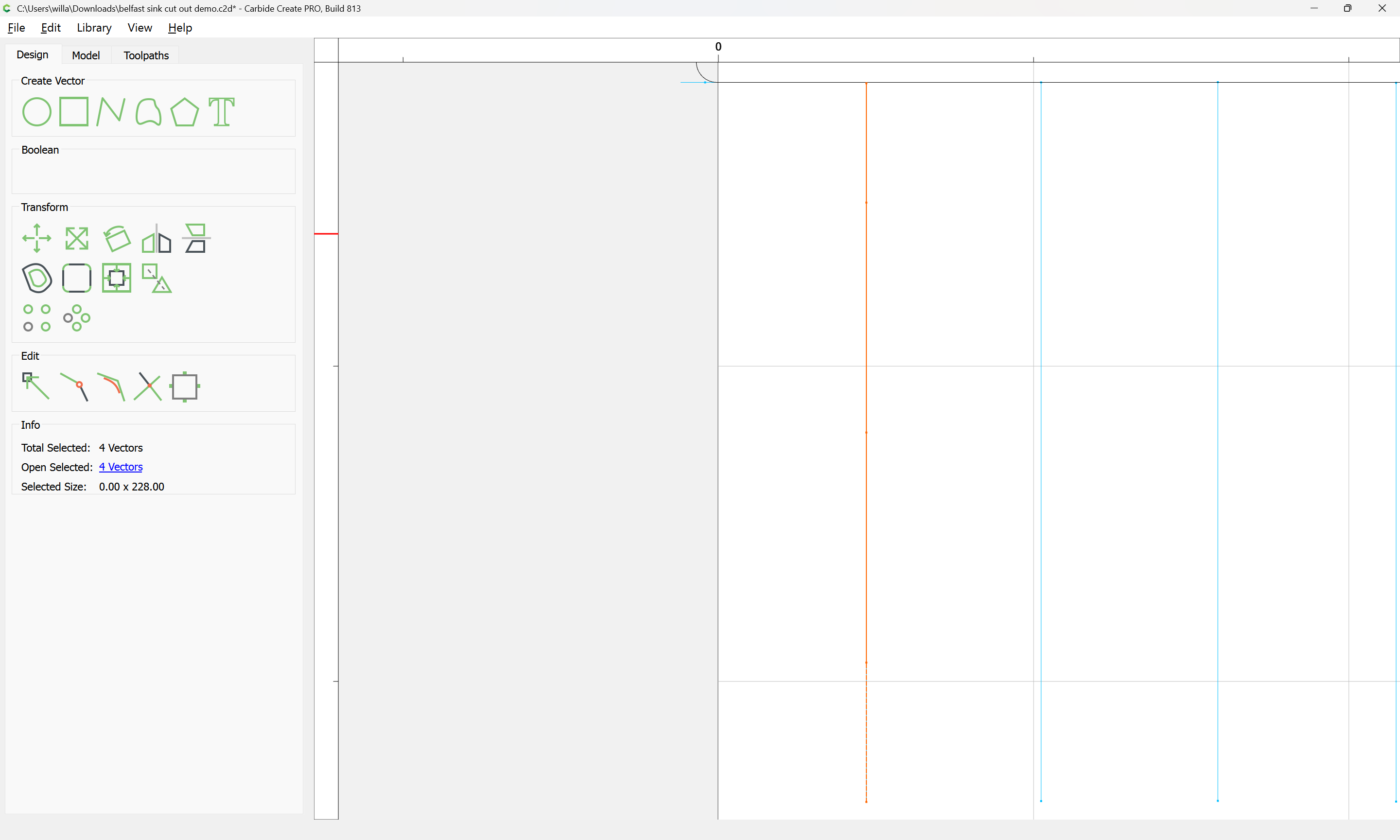
which may now be deleted:
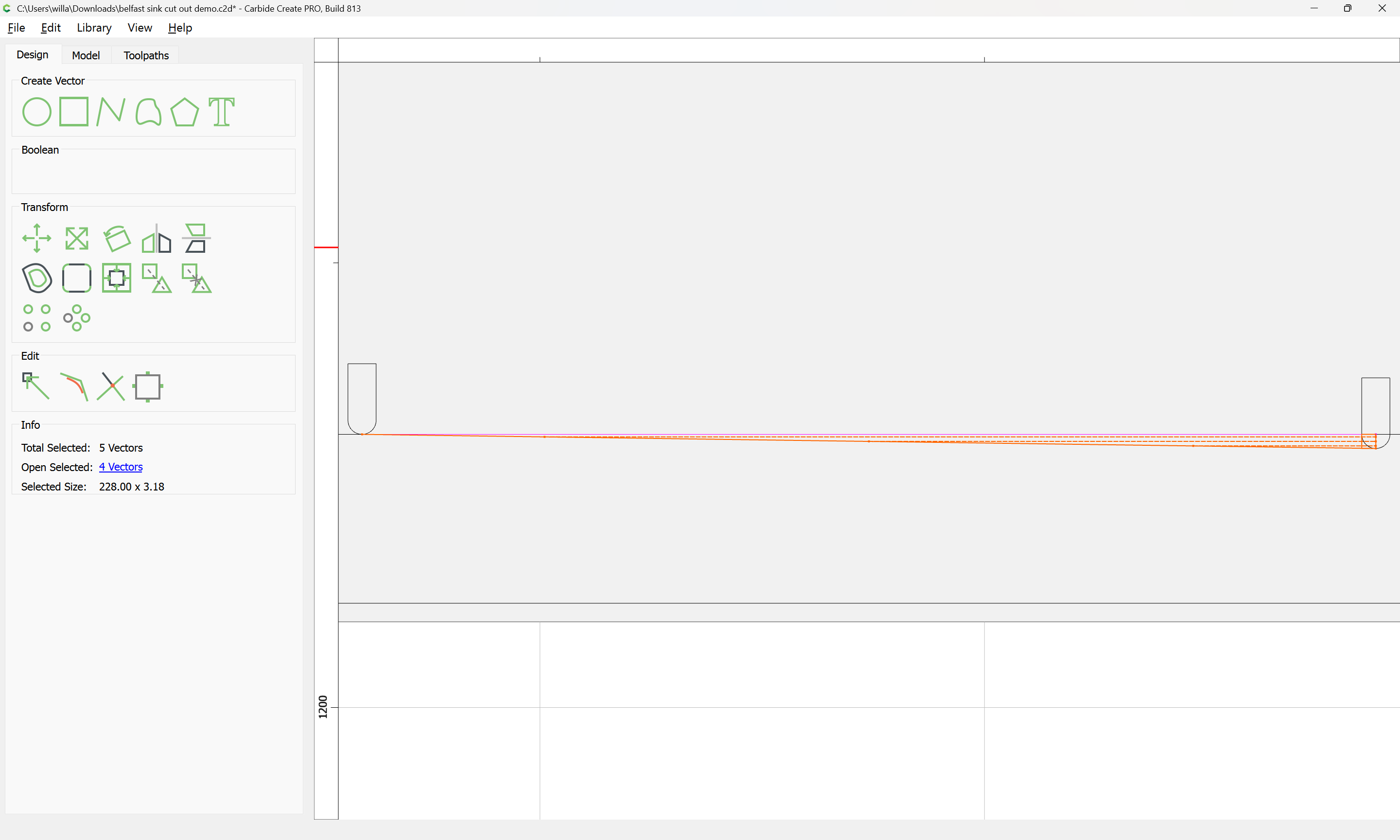
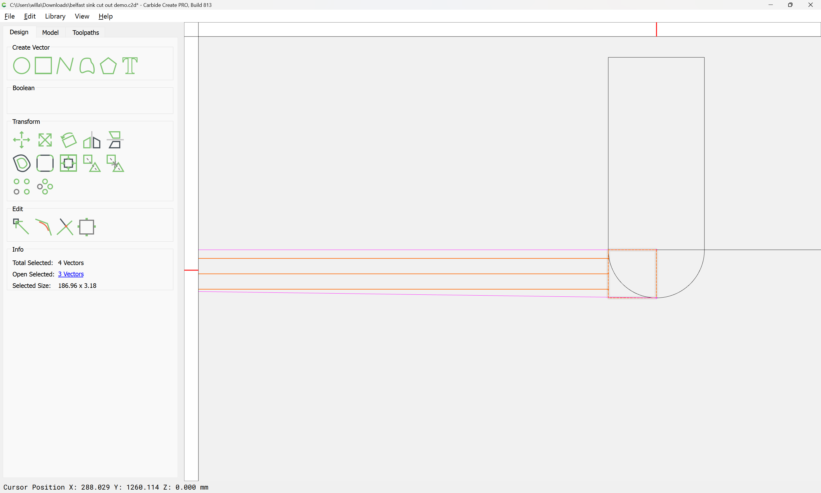
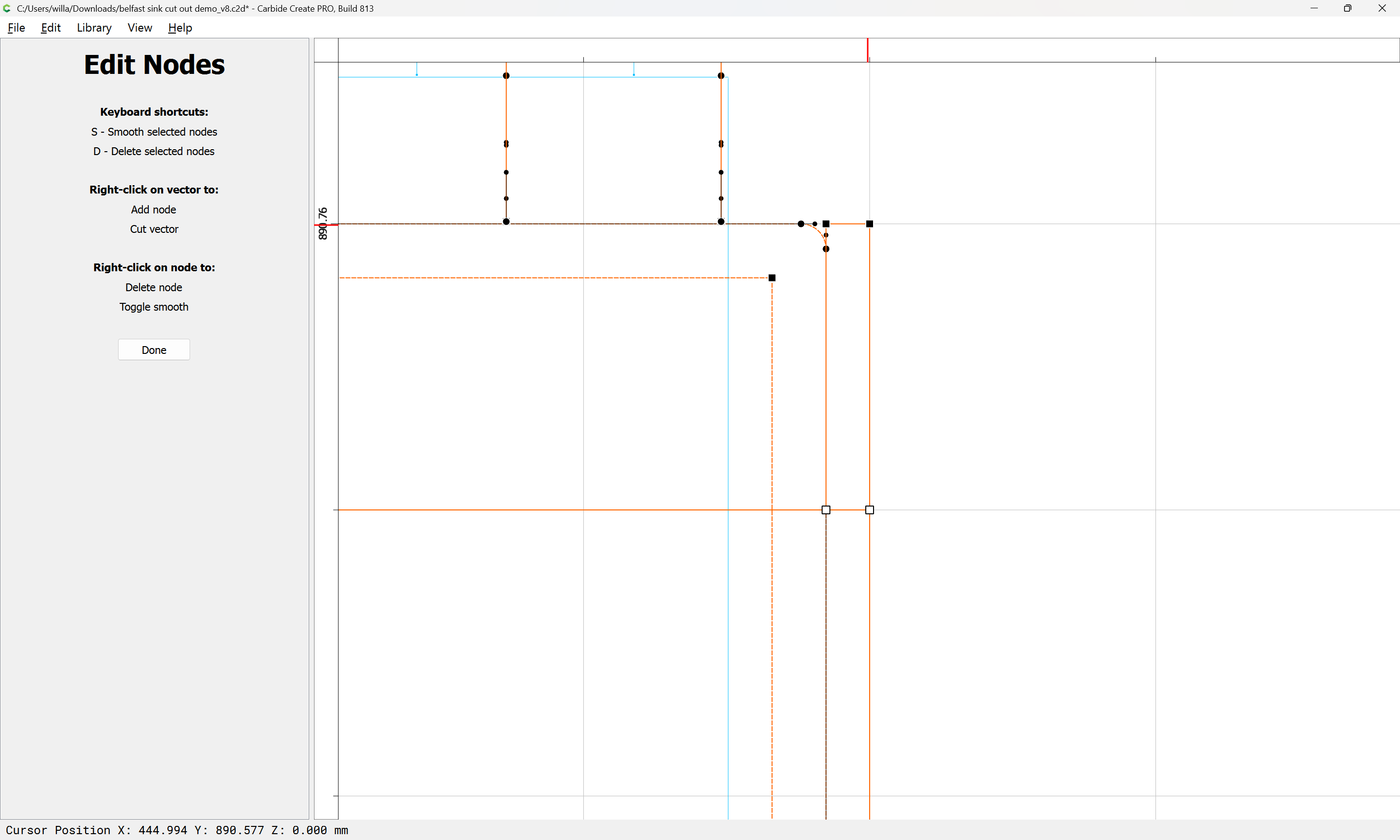
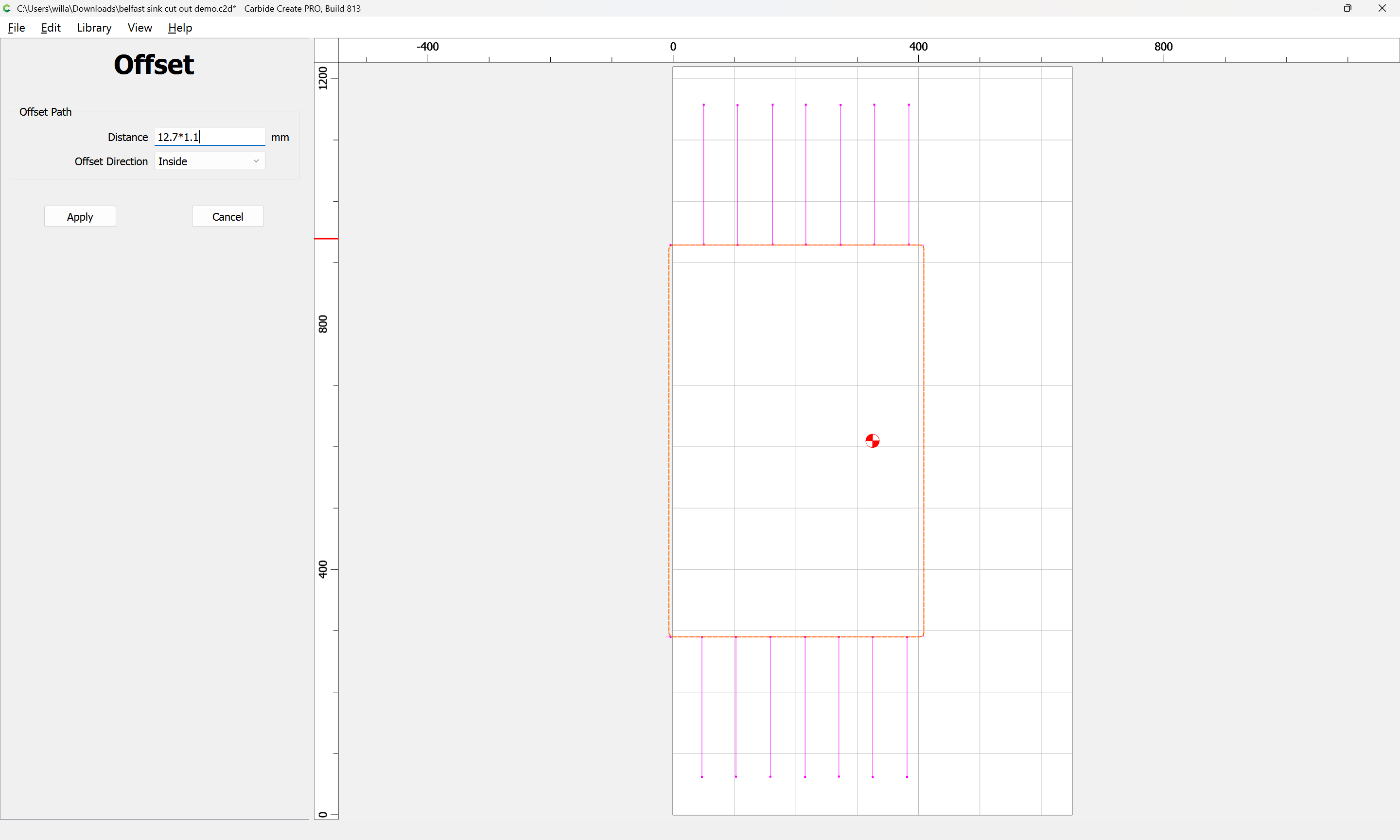
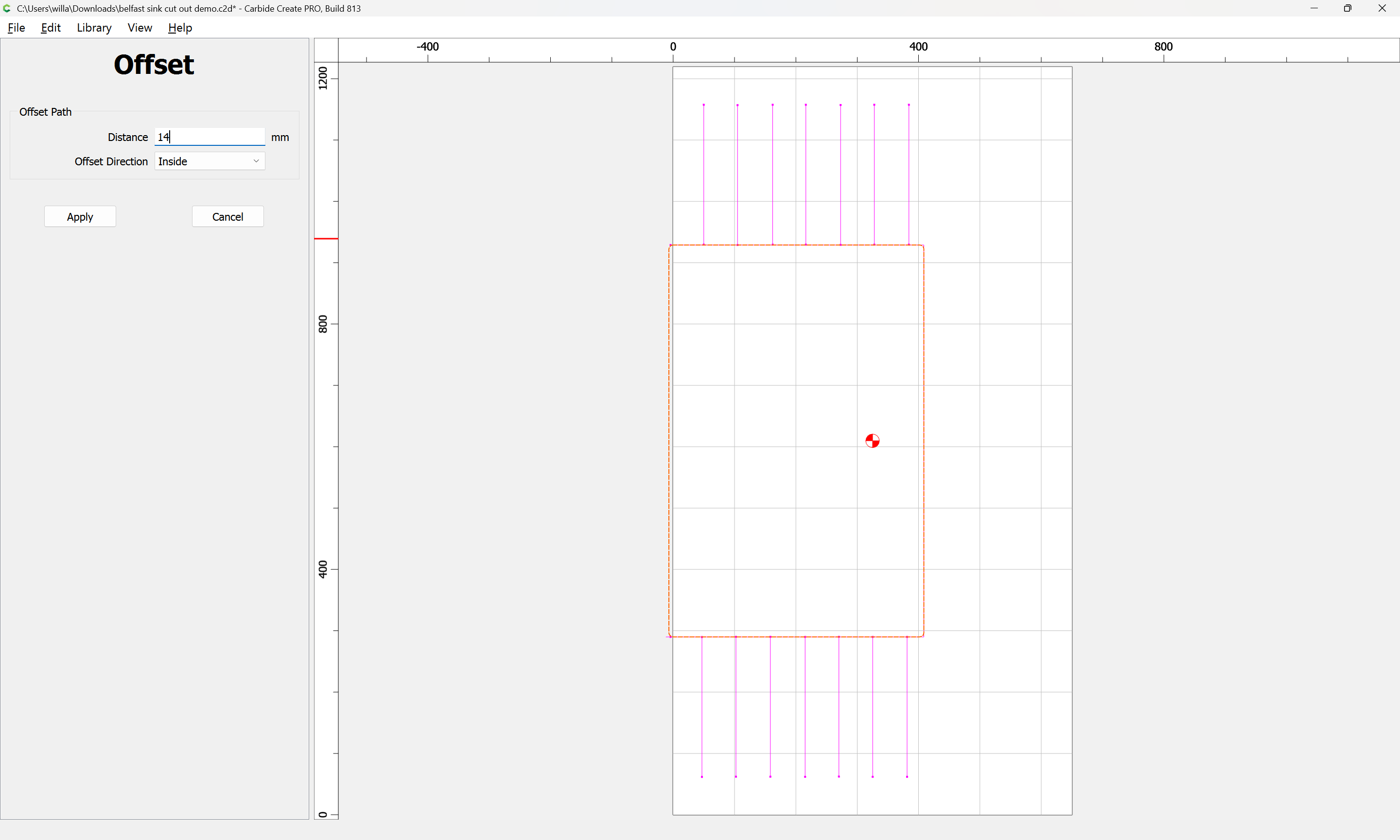
Inset the rectangle by tool diameter plus 10% or so:
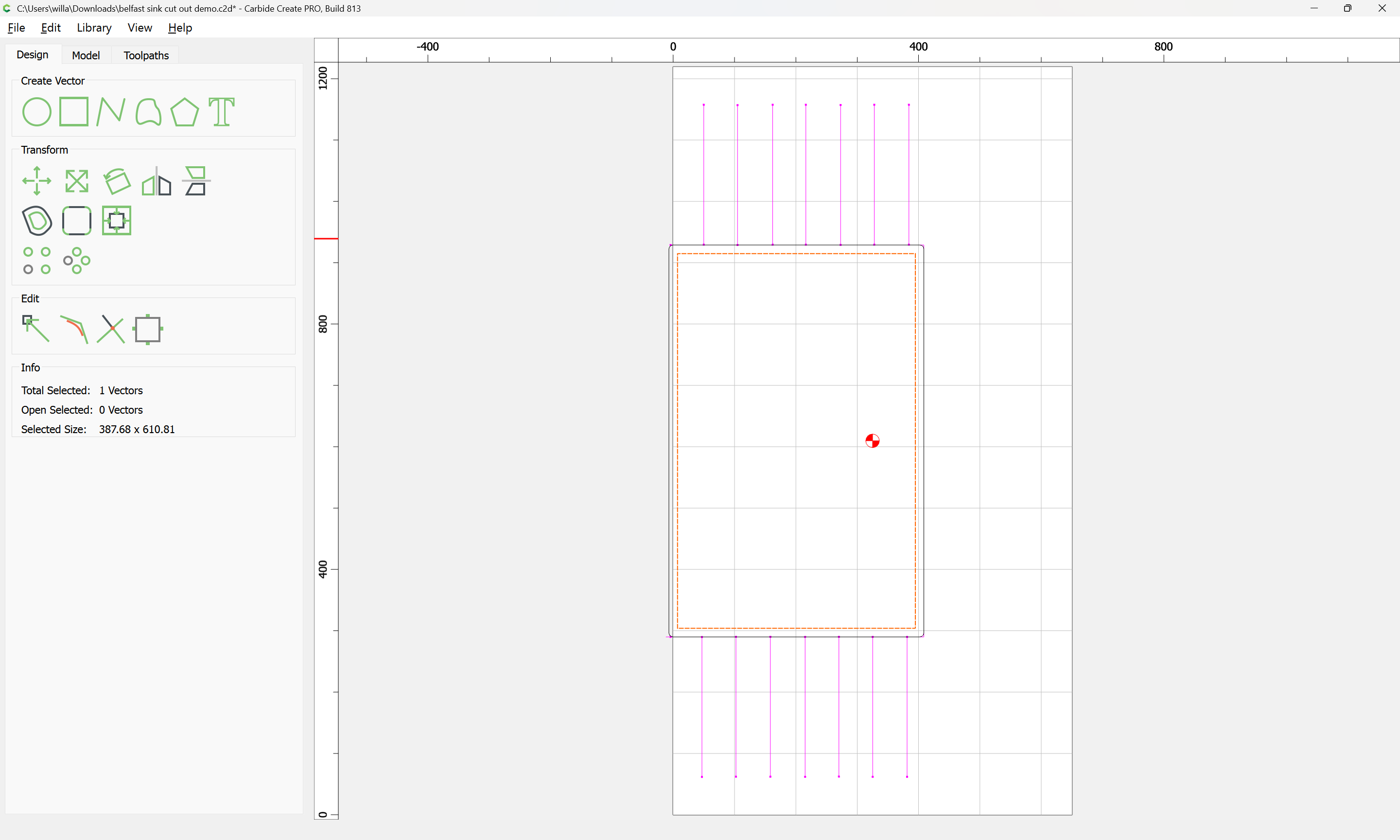
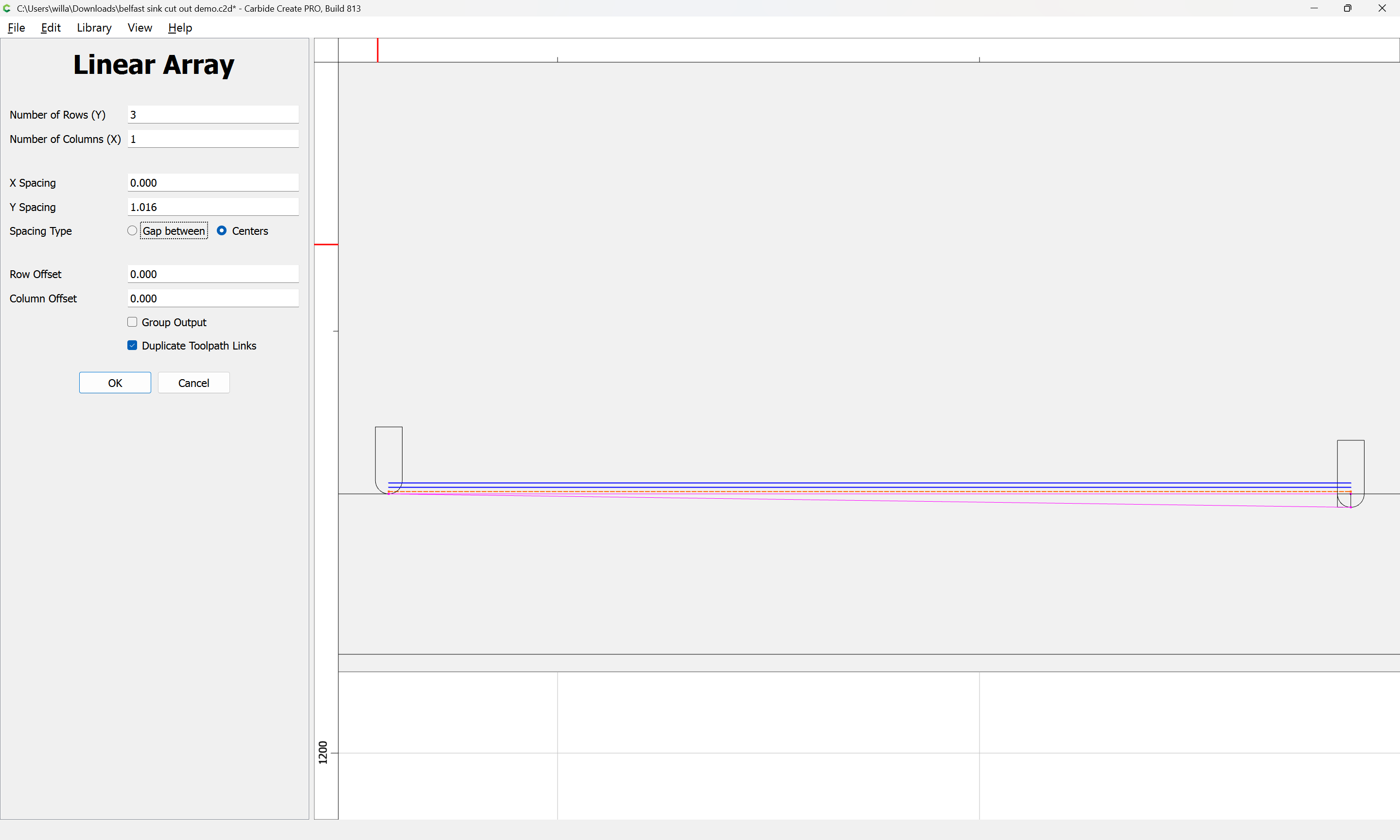
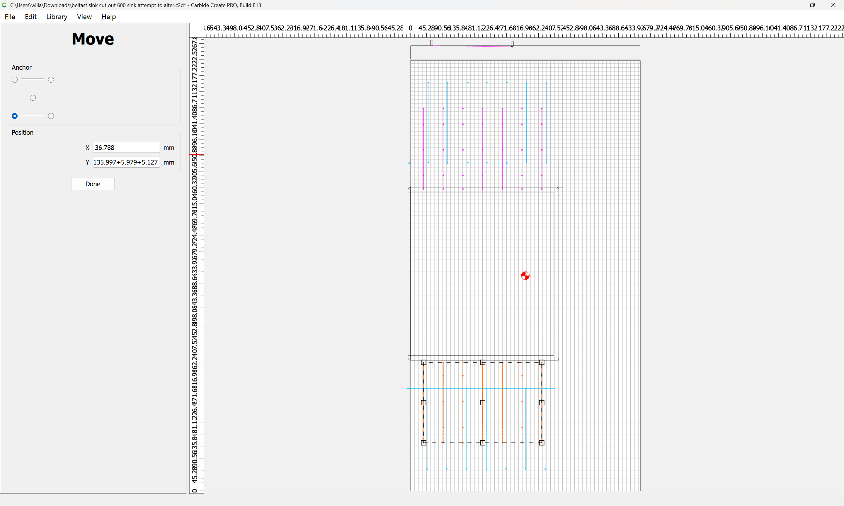
Duplicate the resultant geometry and move it to the left:

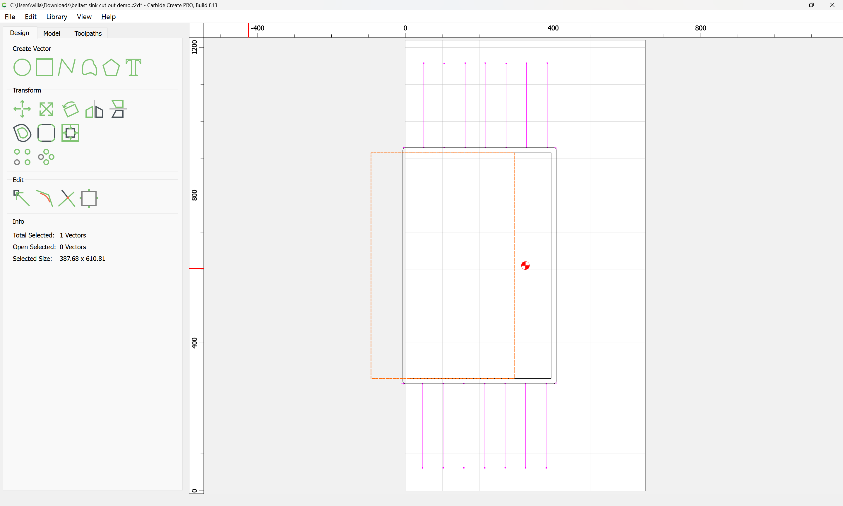
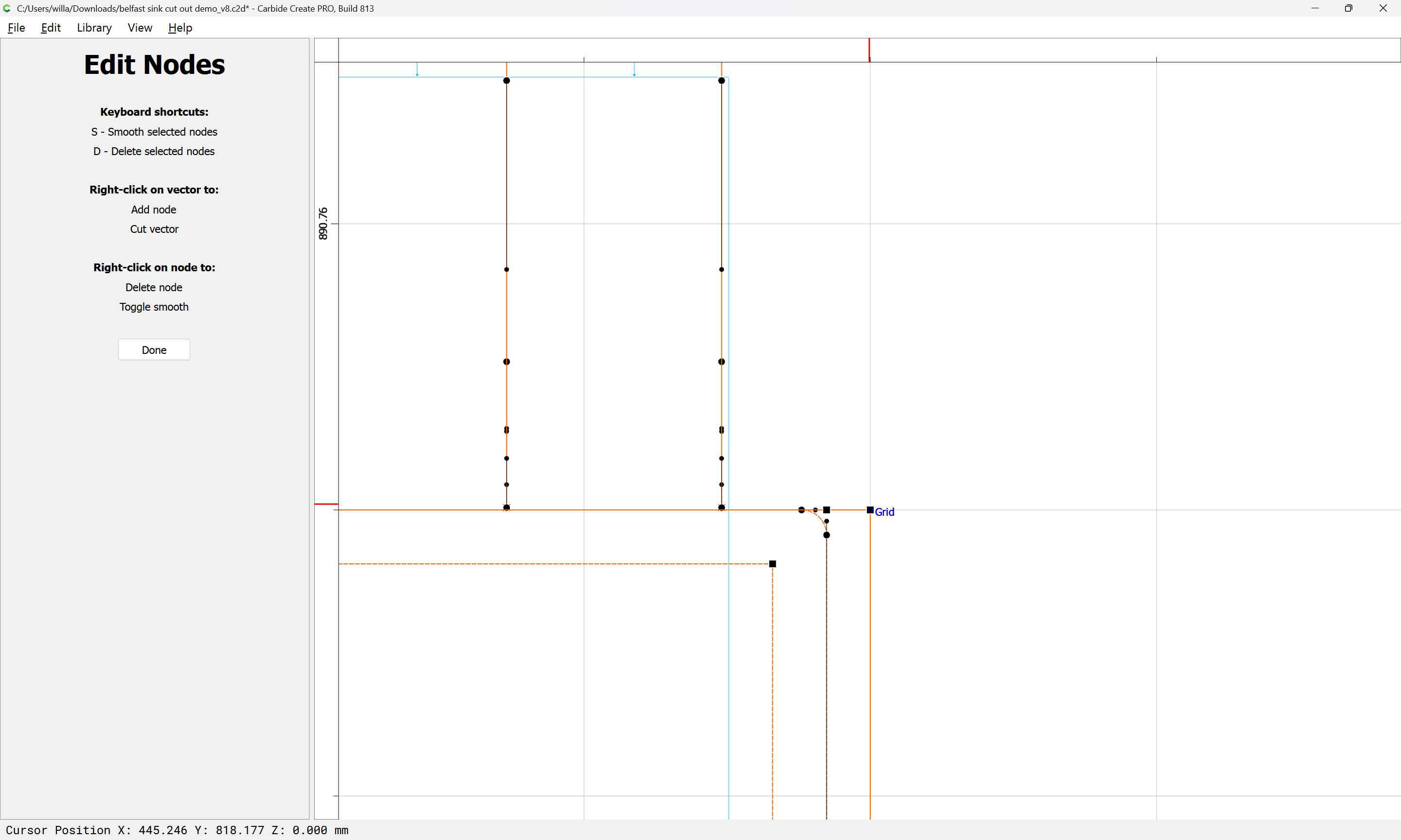
and then union it with the inset in the original position:
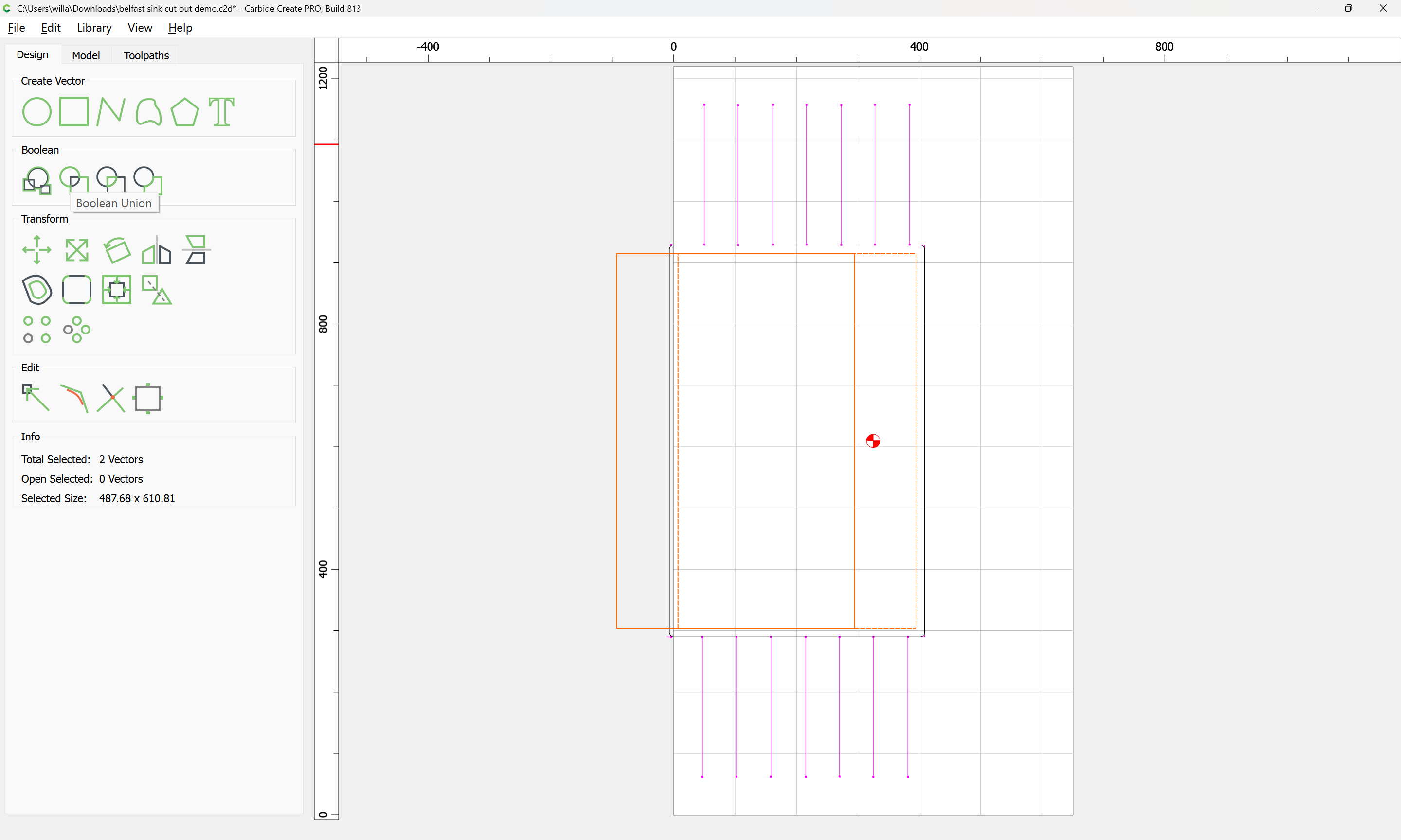
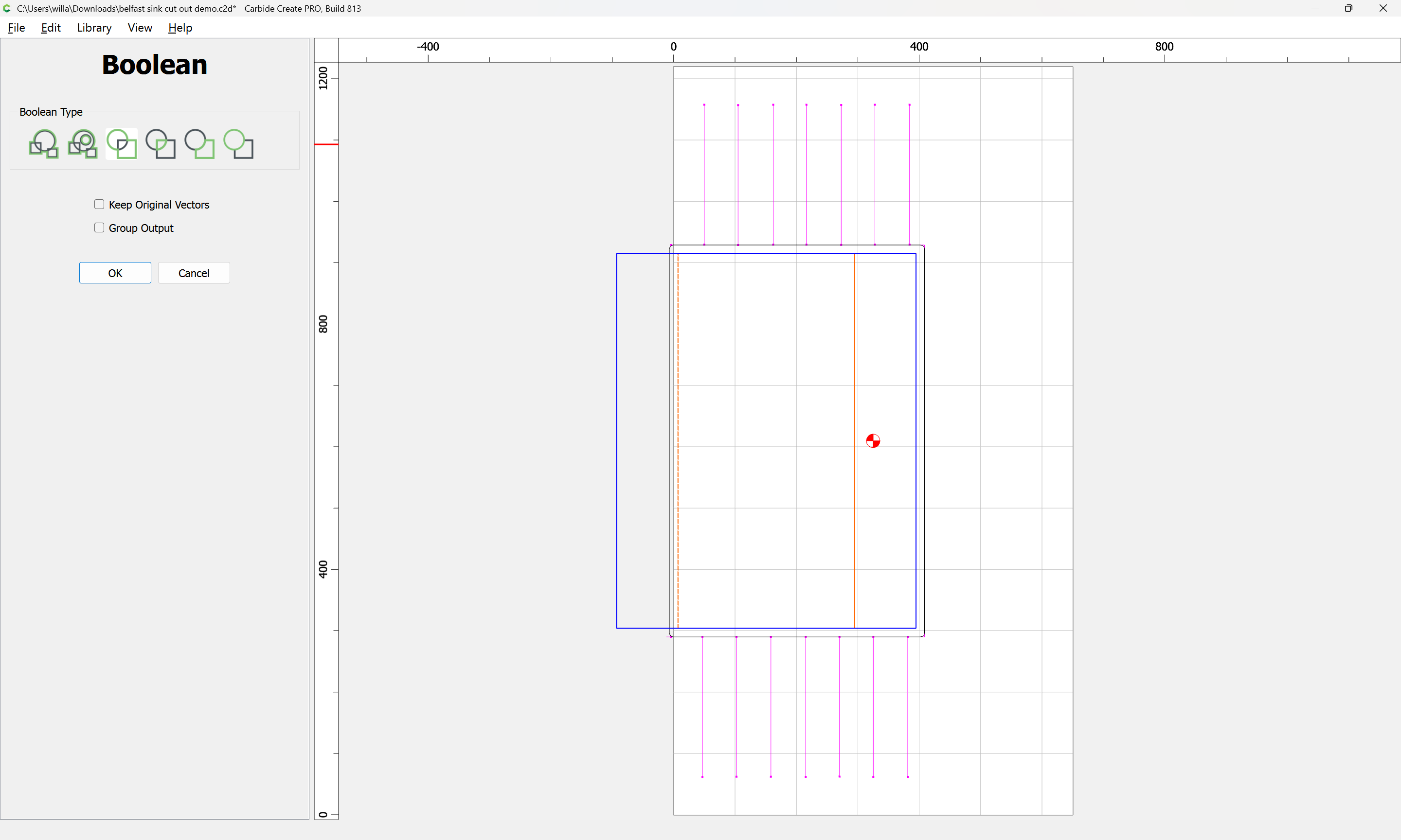
OK

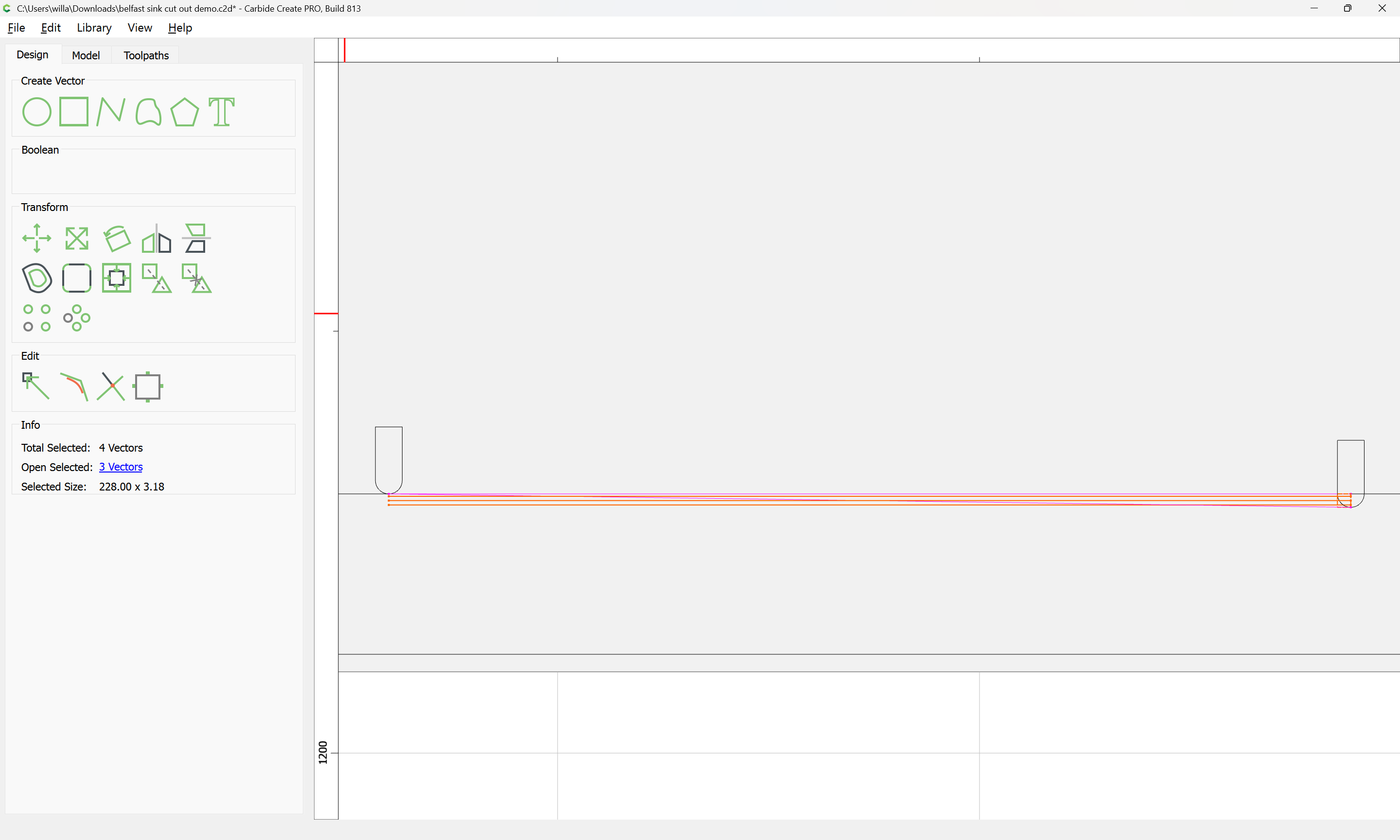
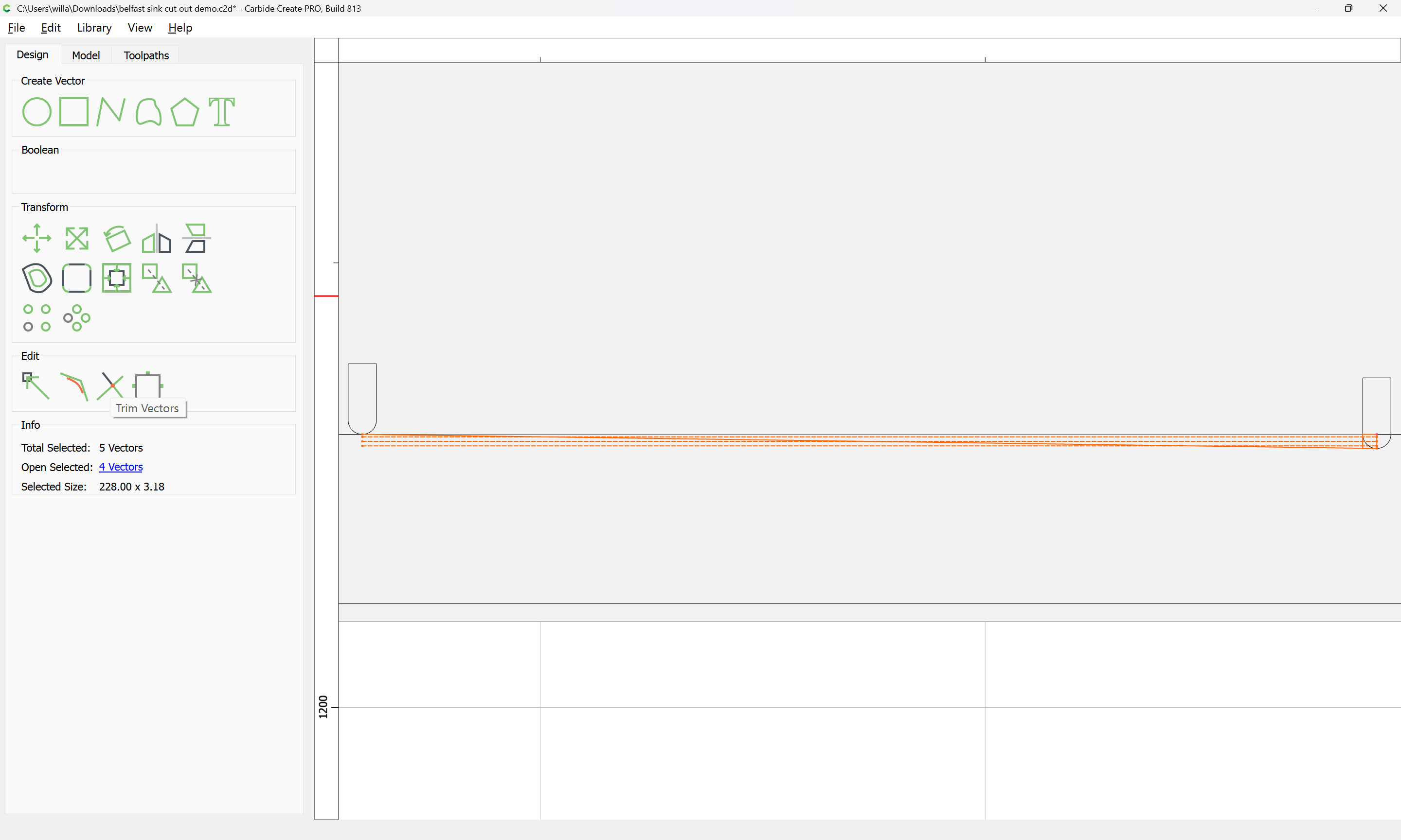
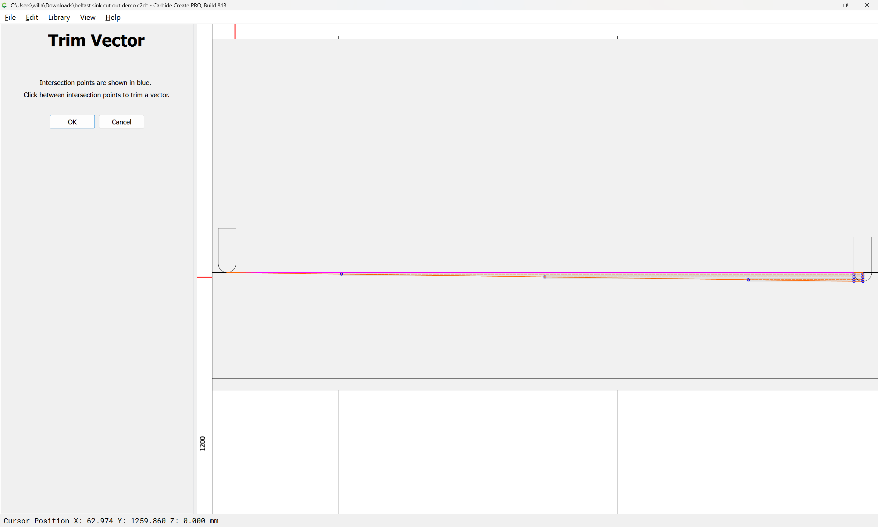
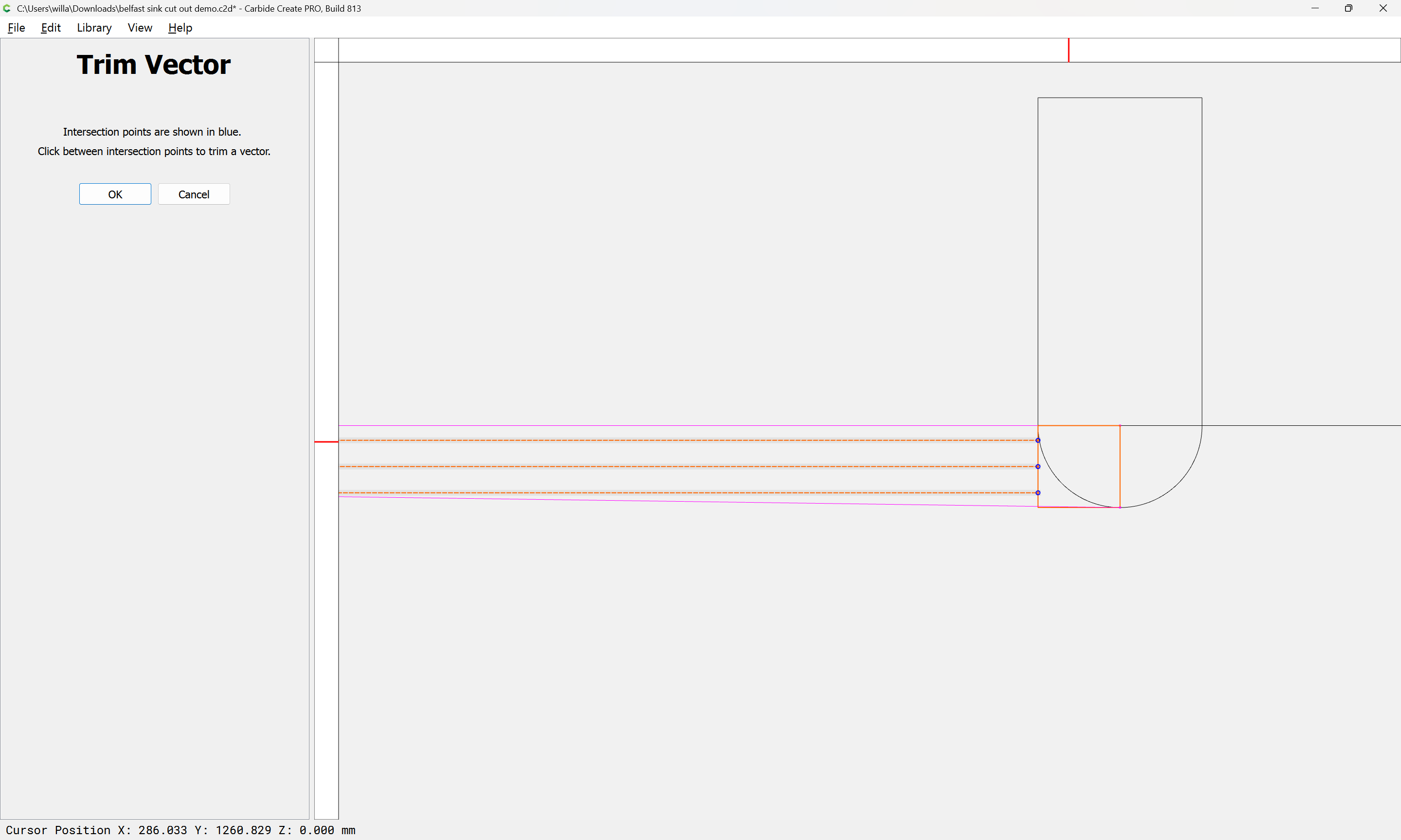
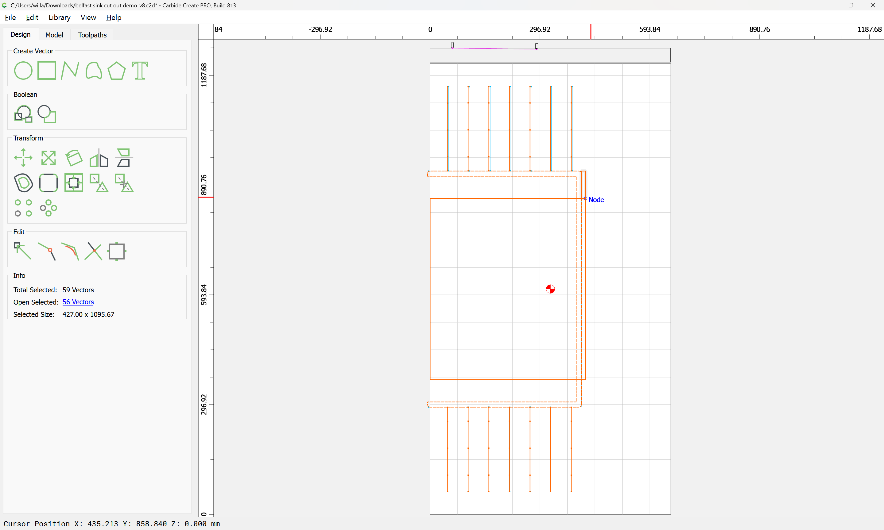
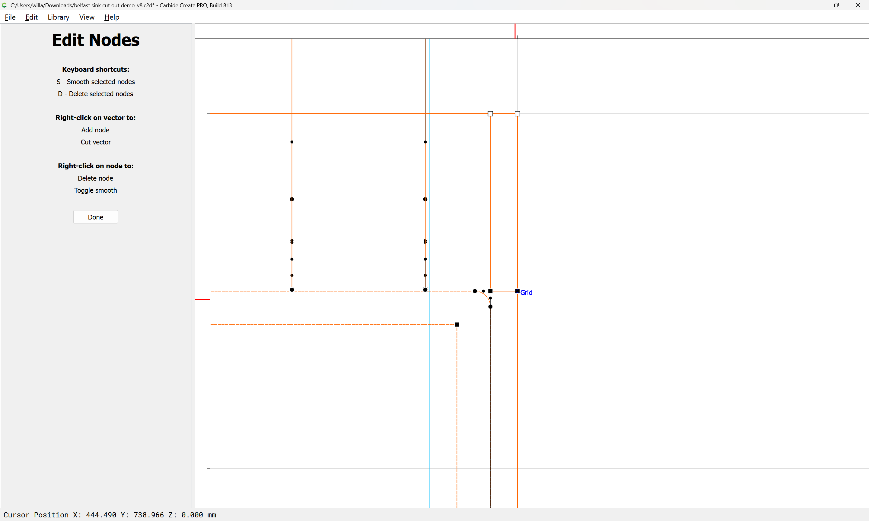
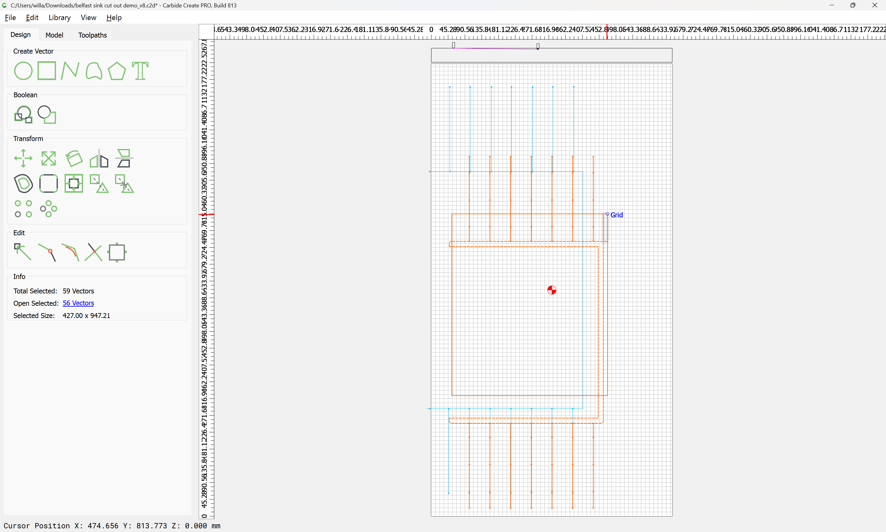
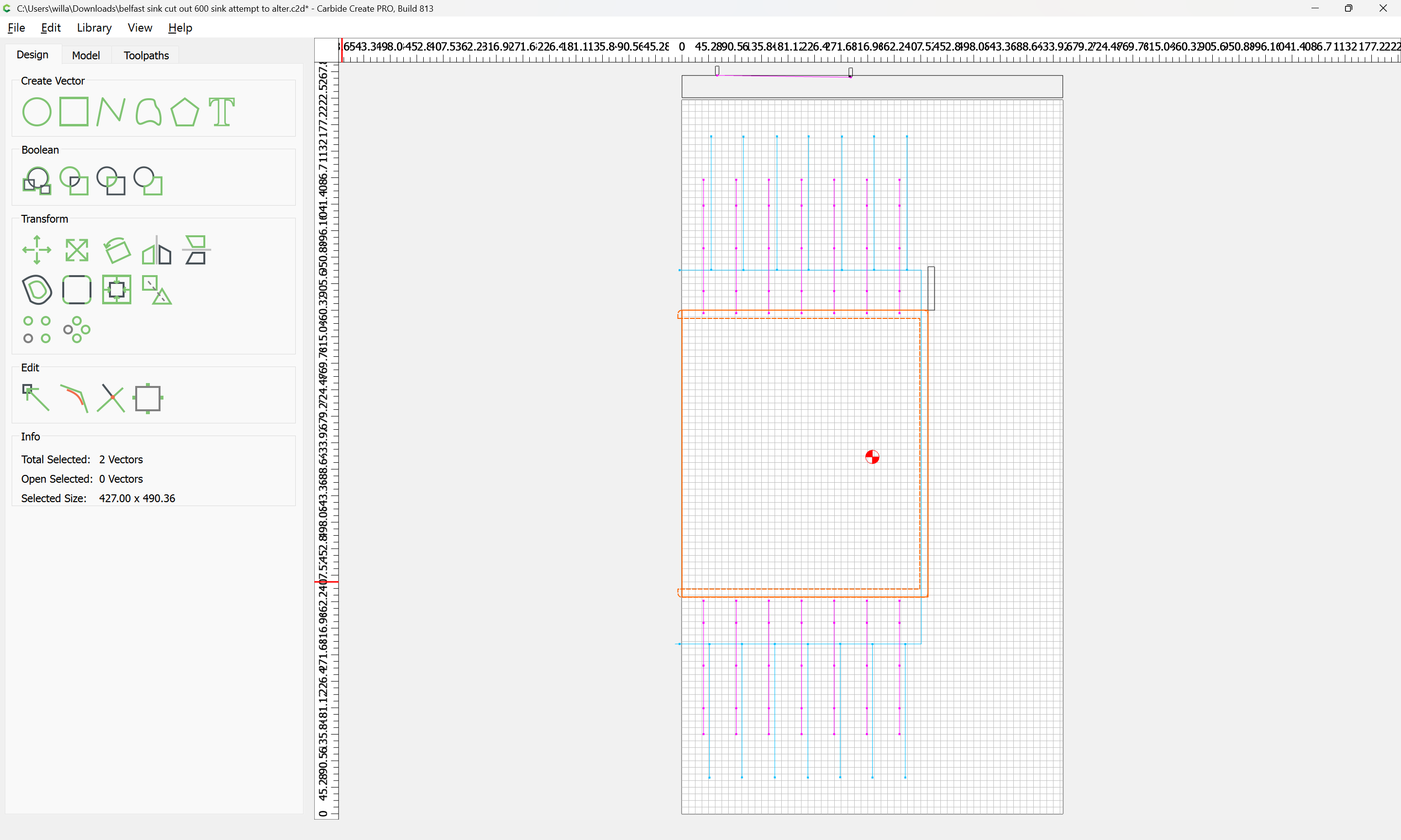
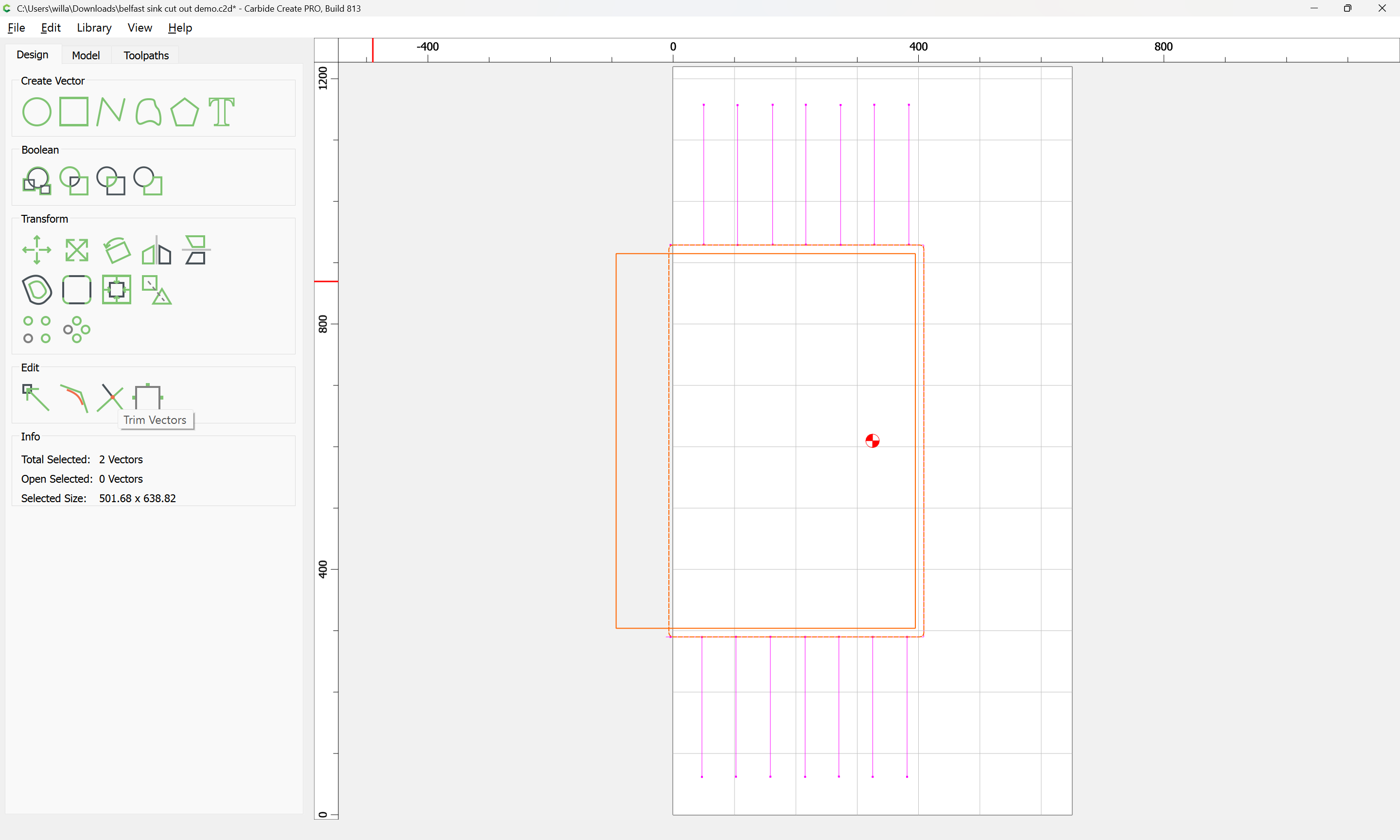
Select both rectangles and use Trim Vectors:
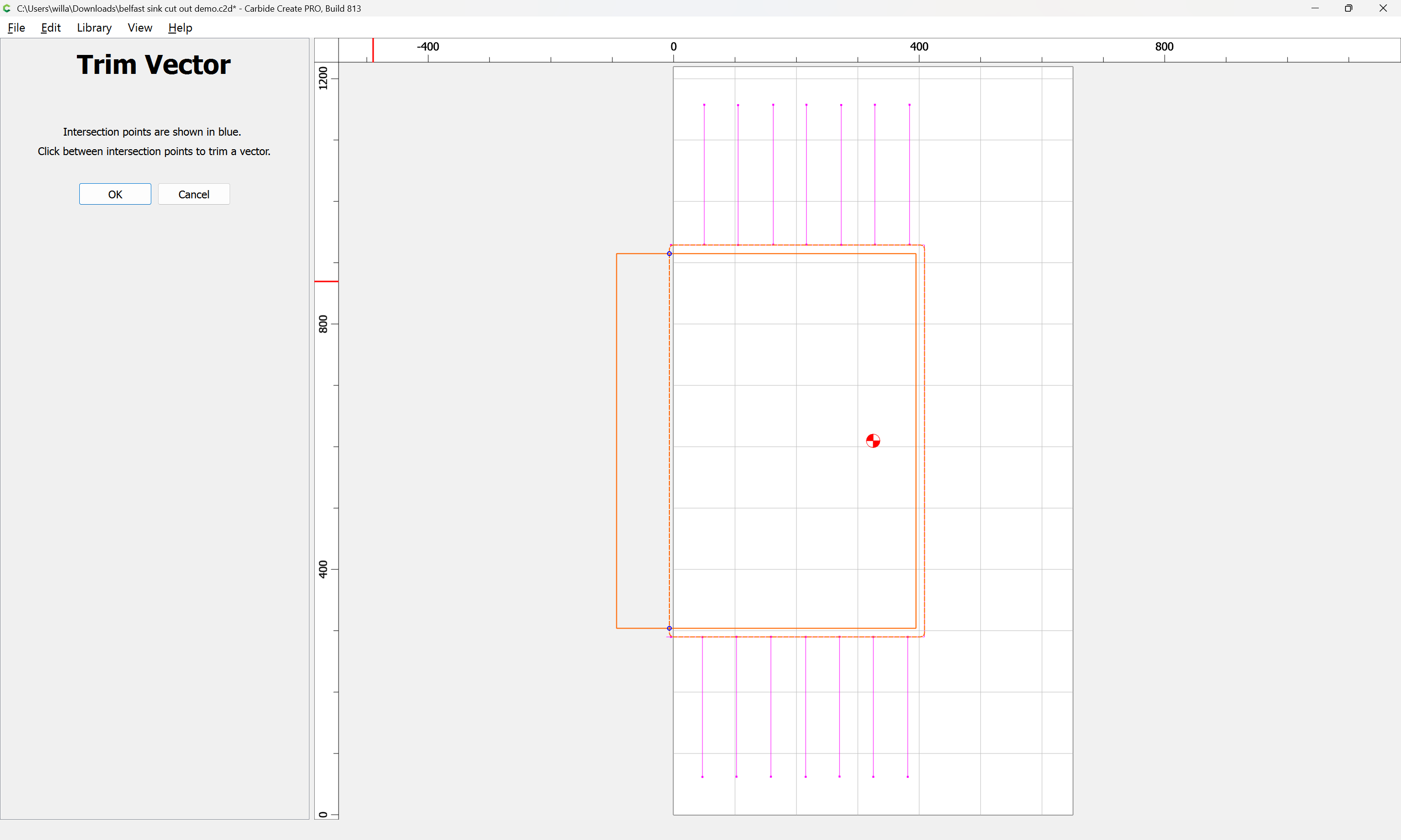
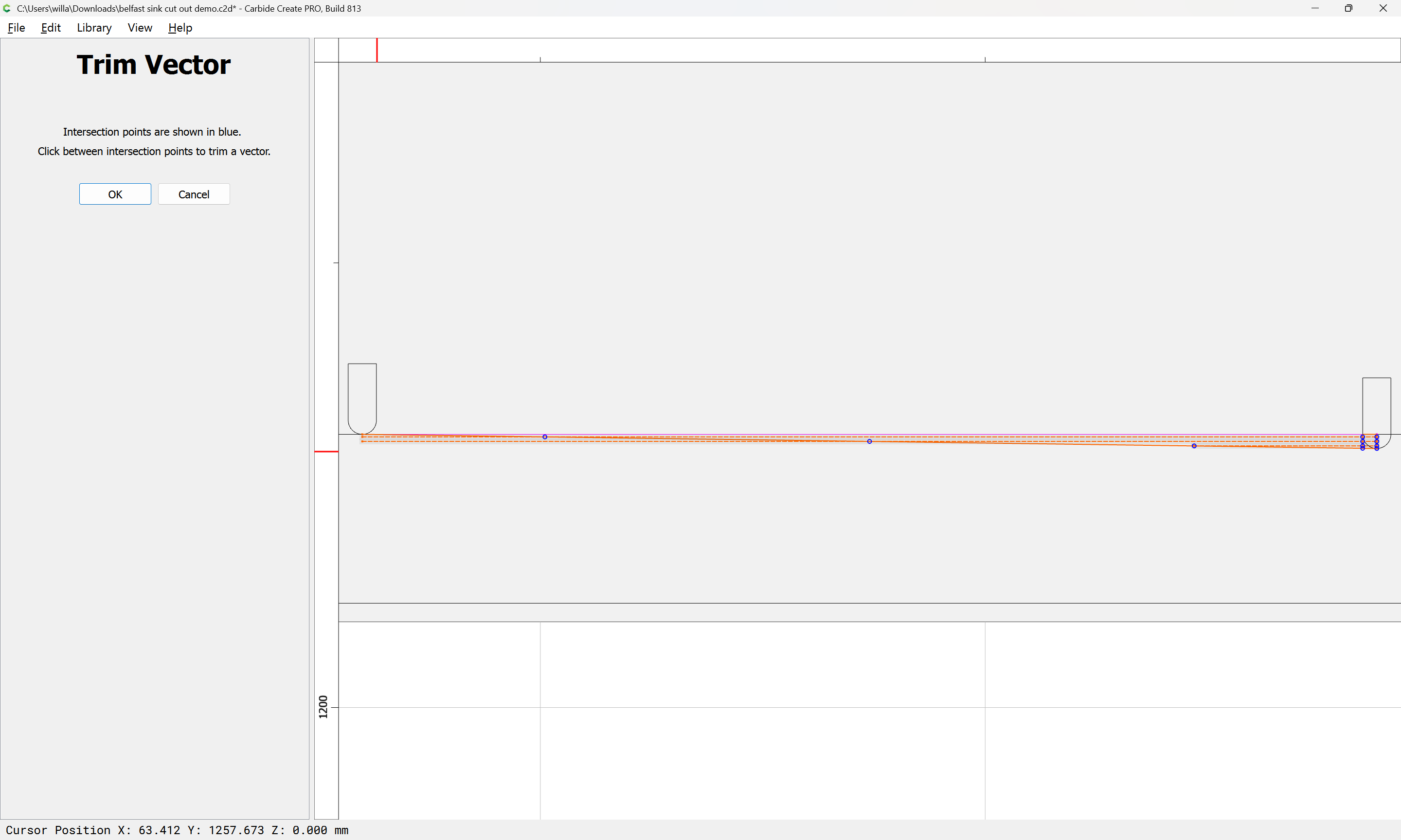
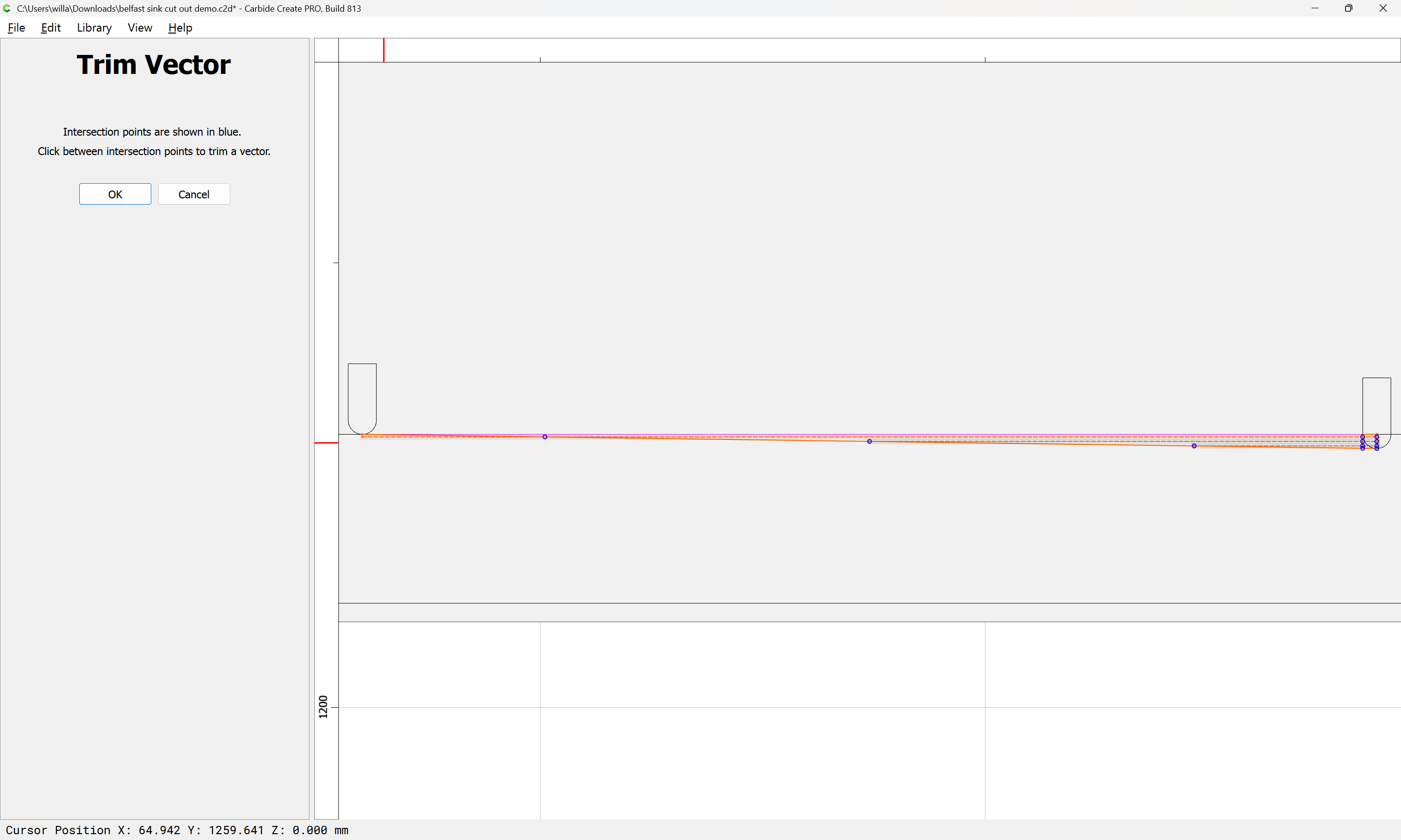
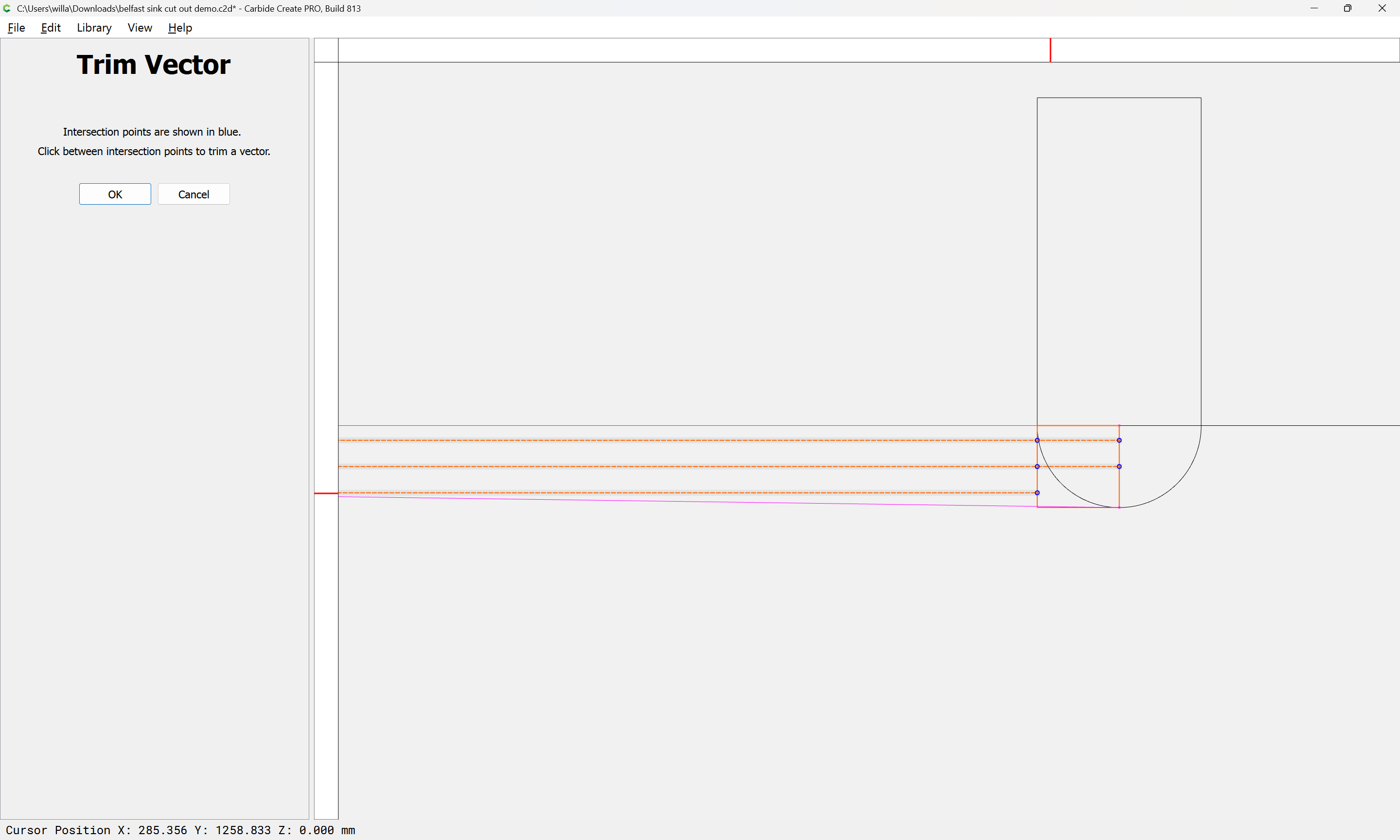
to remove what is not wanted:
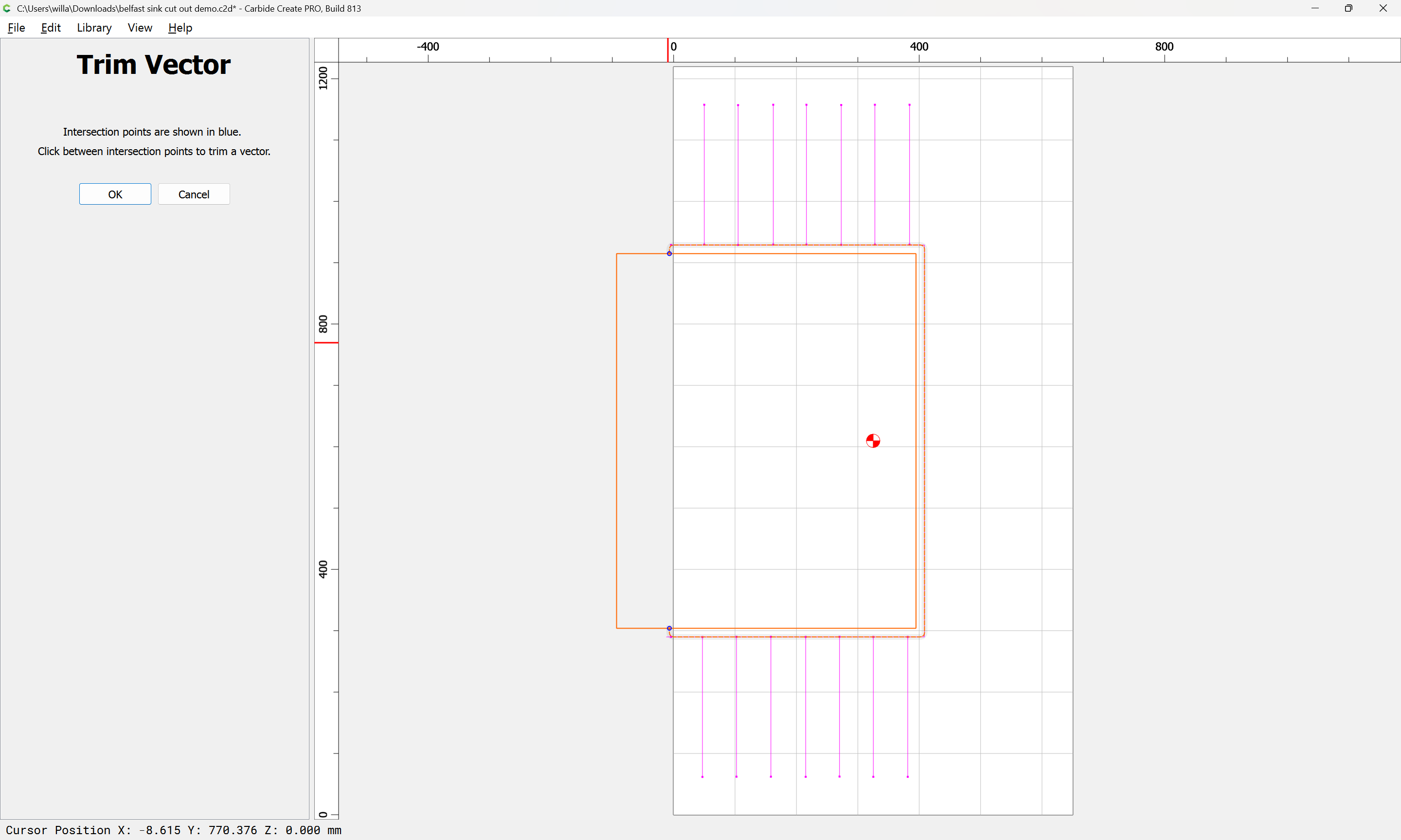
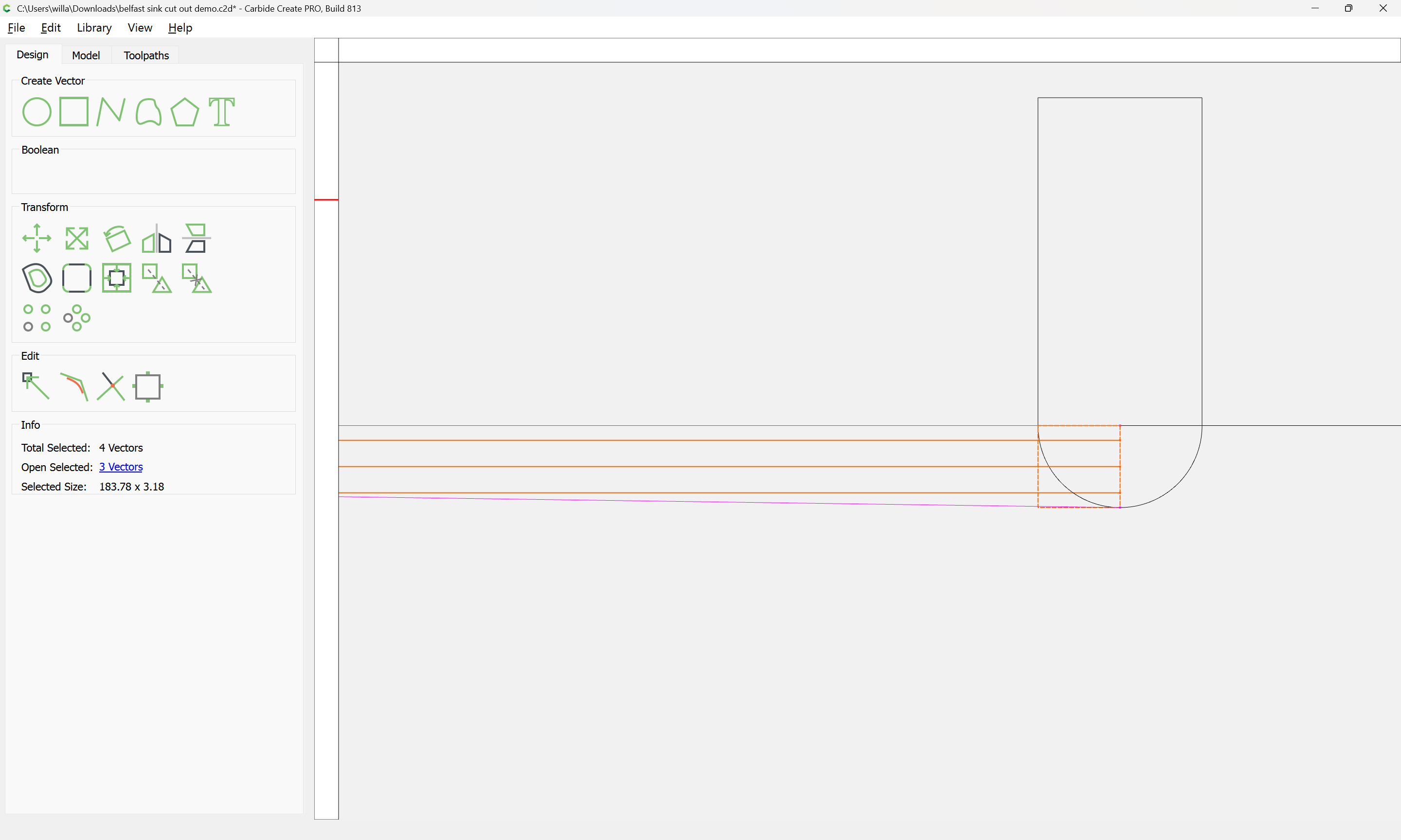
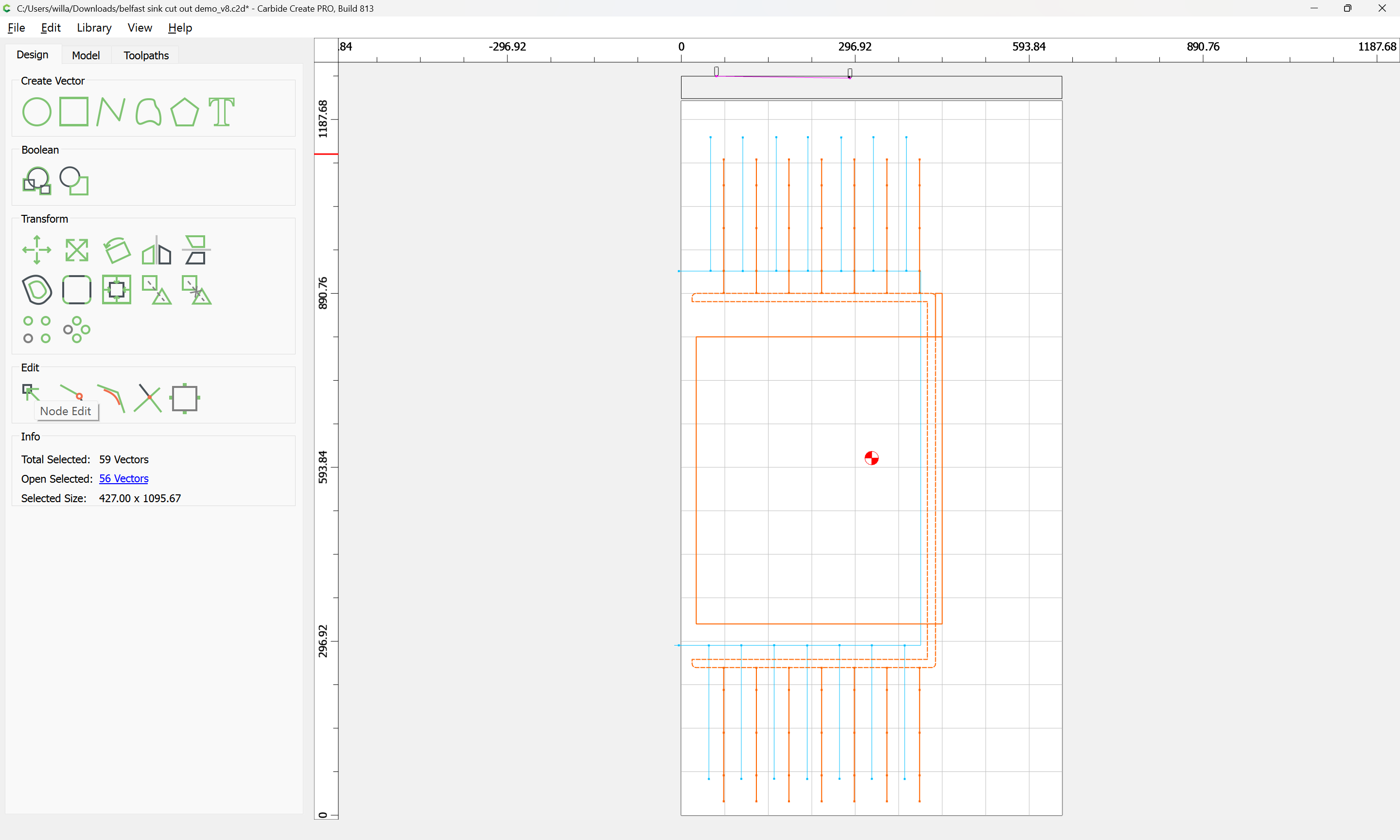
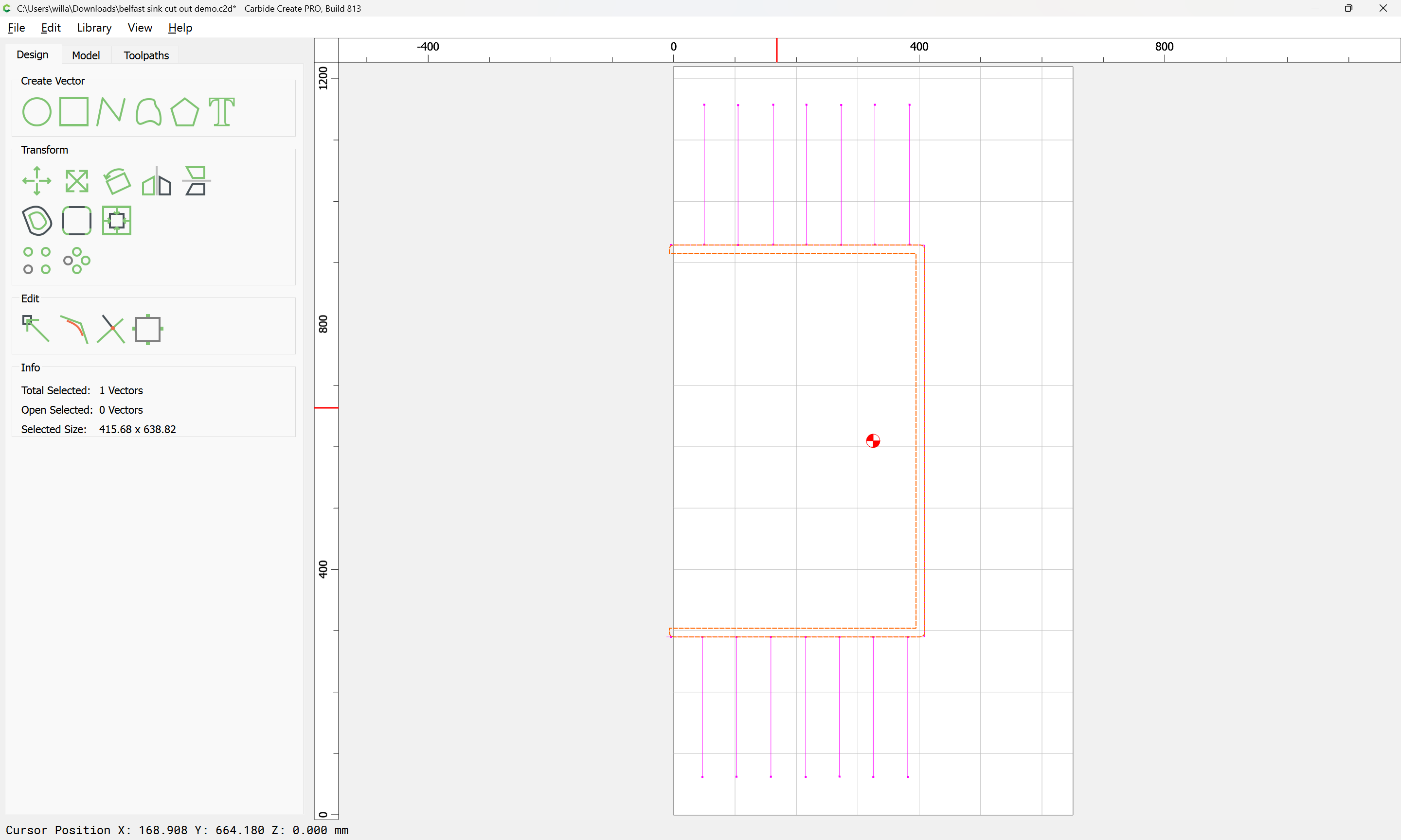
arriving at:
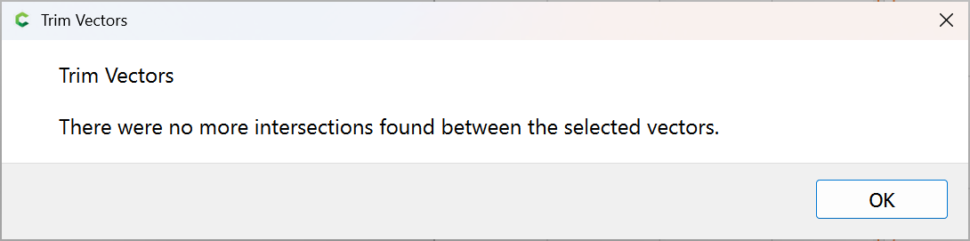
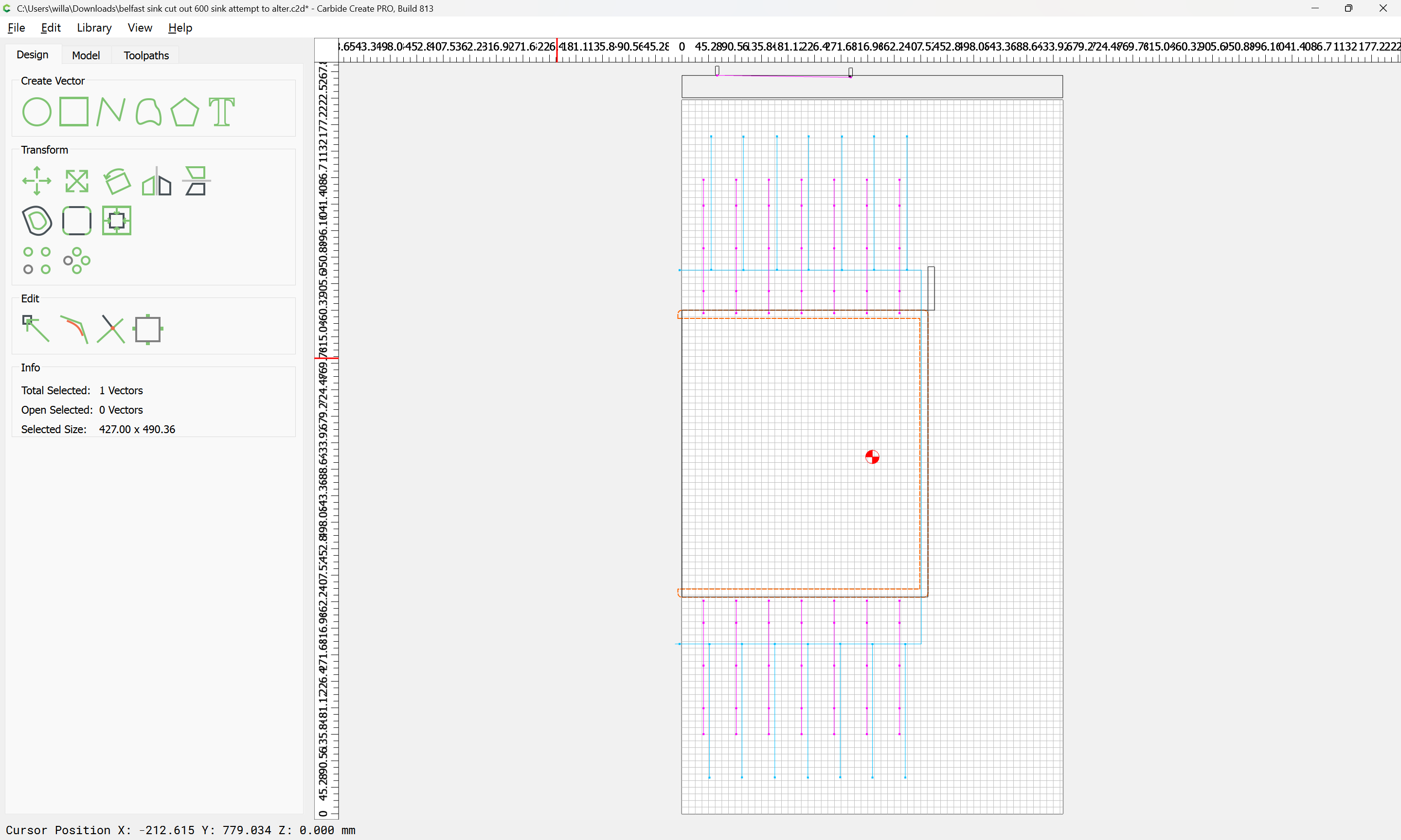
OK
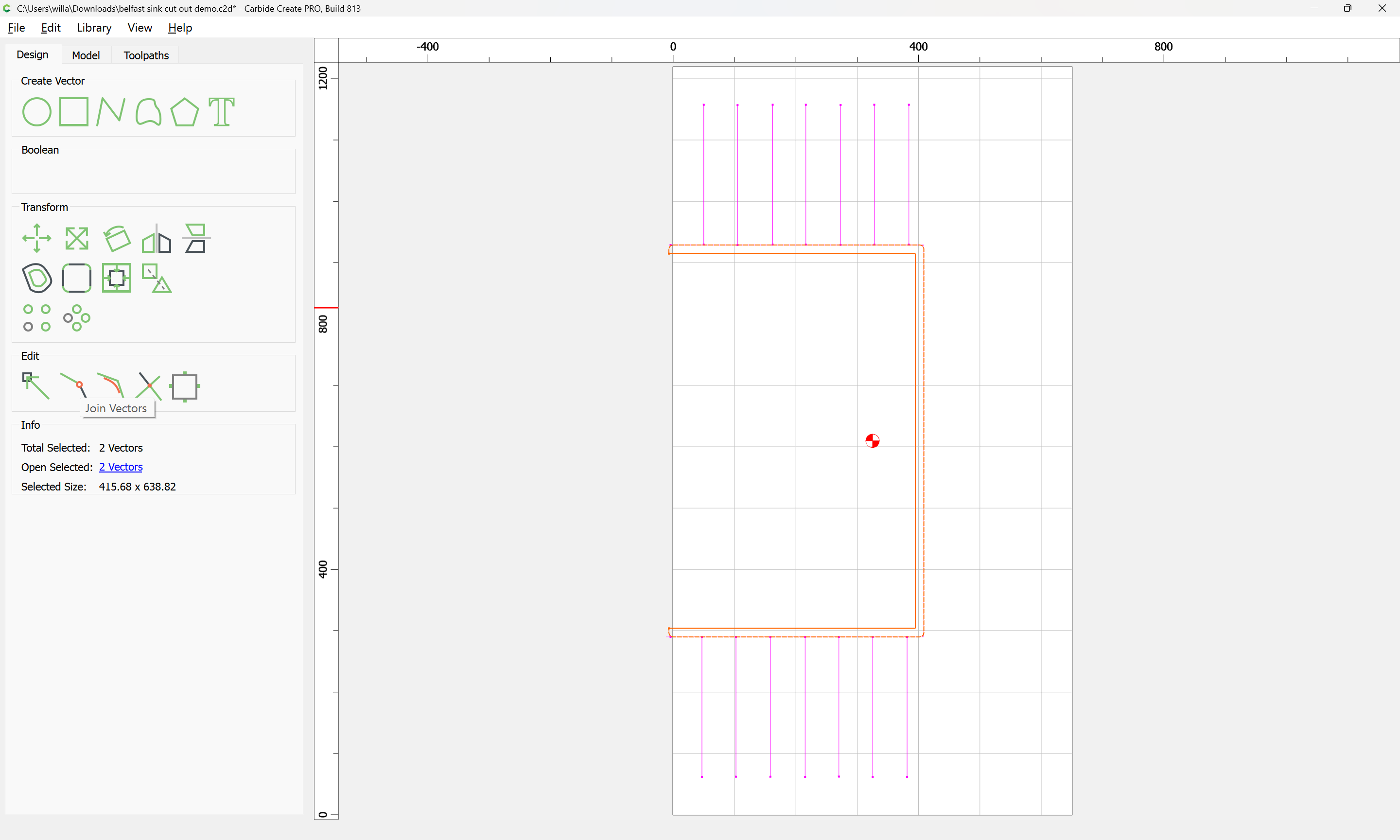
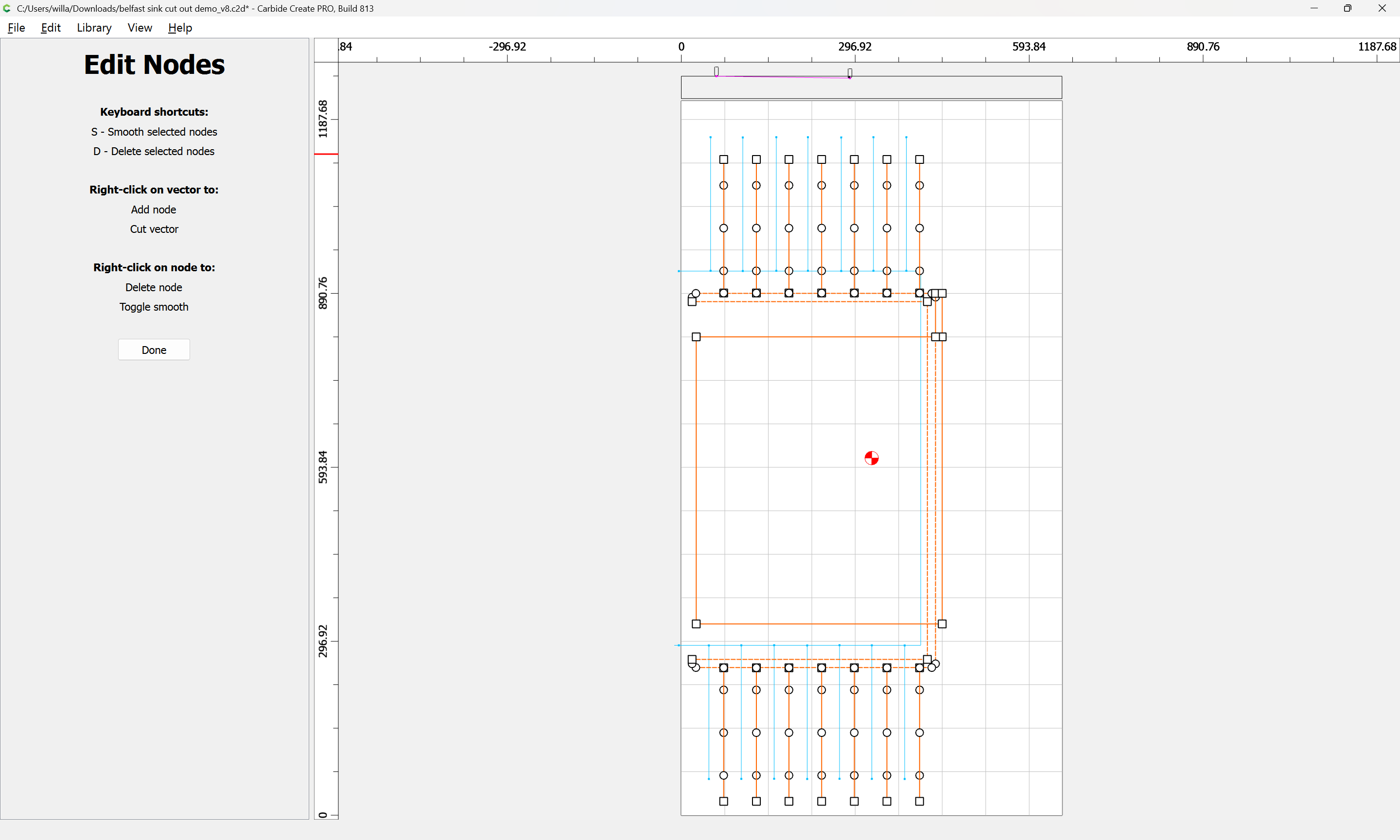
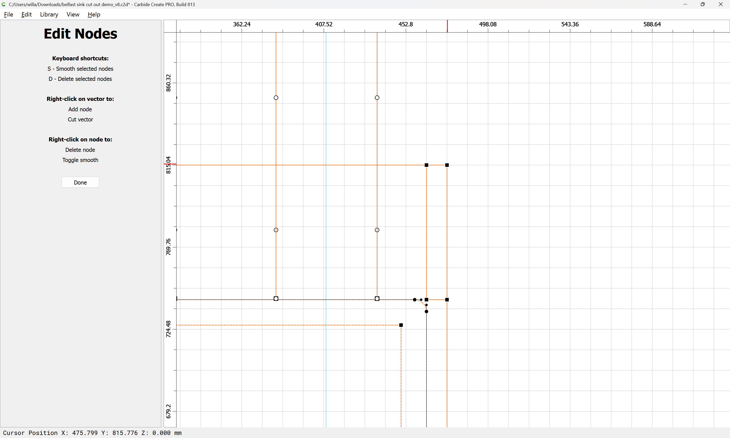
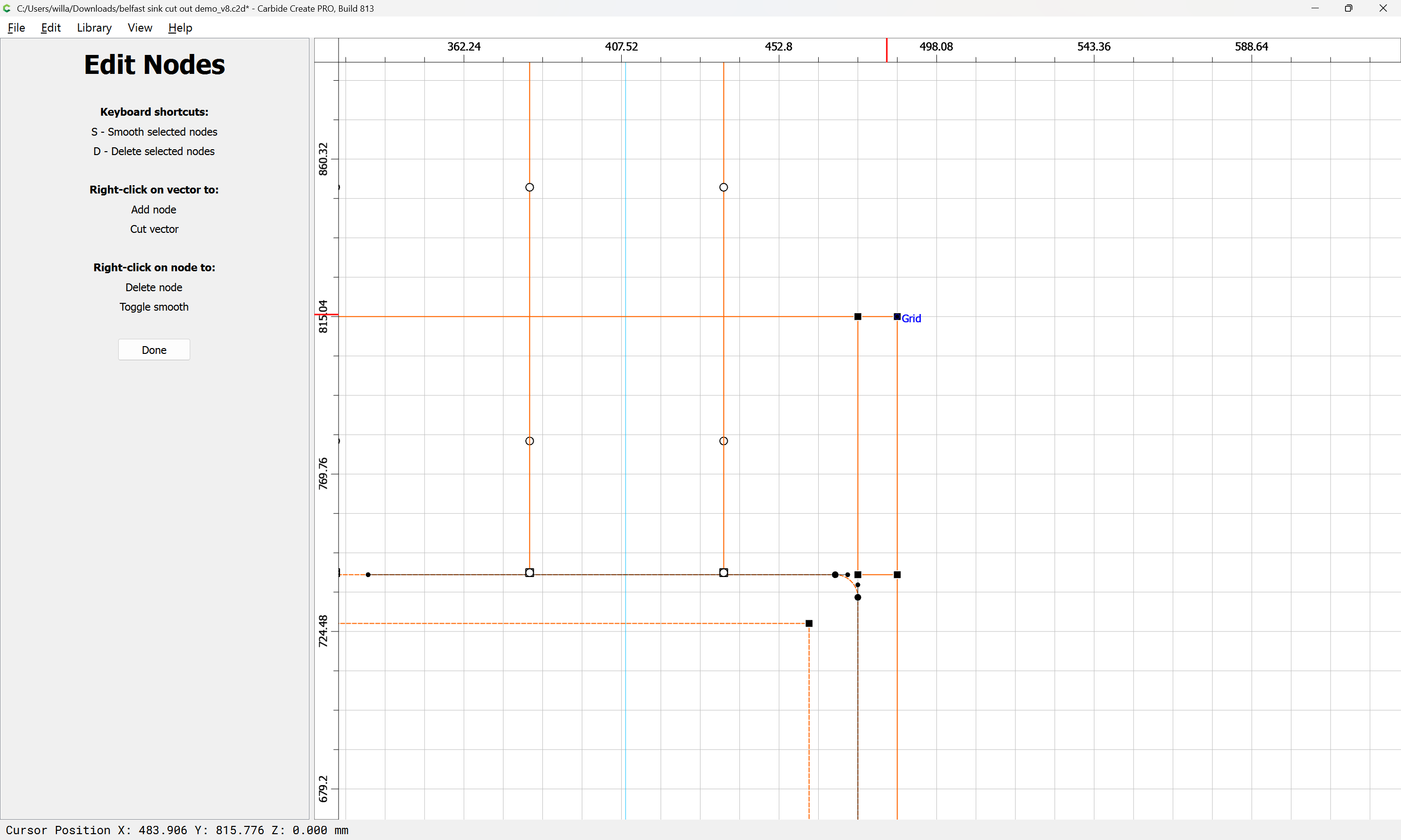
Join Vectors
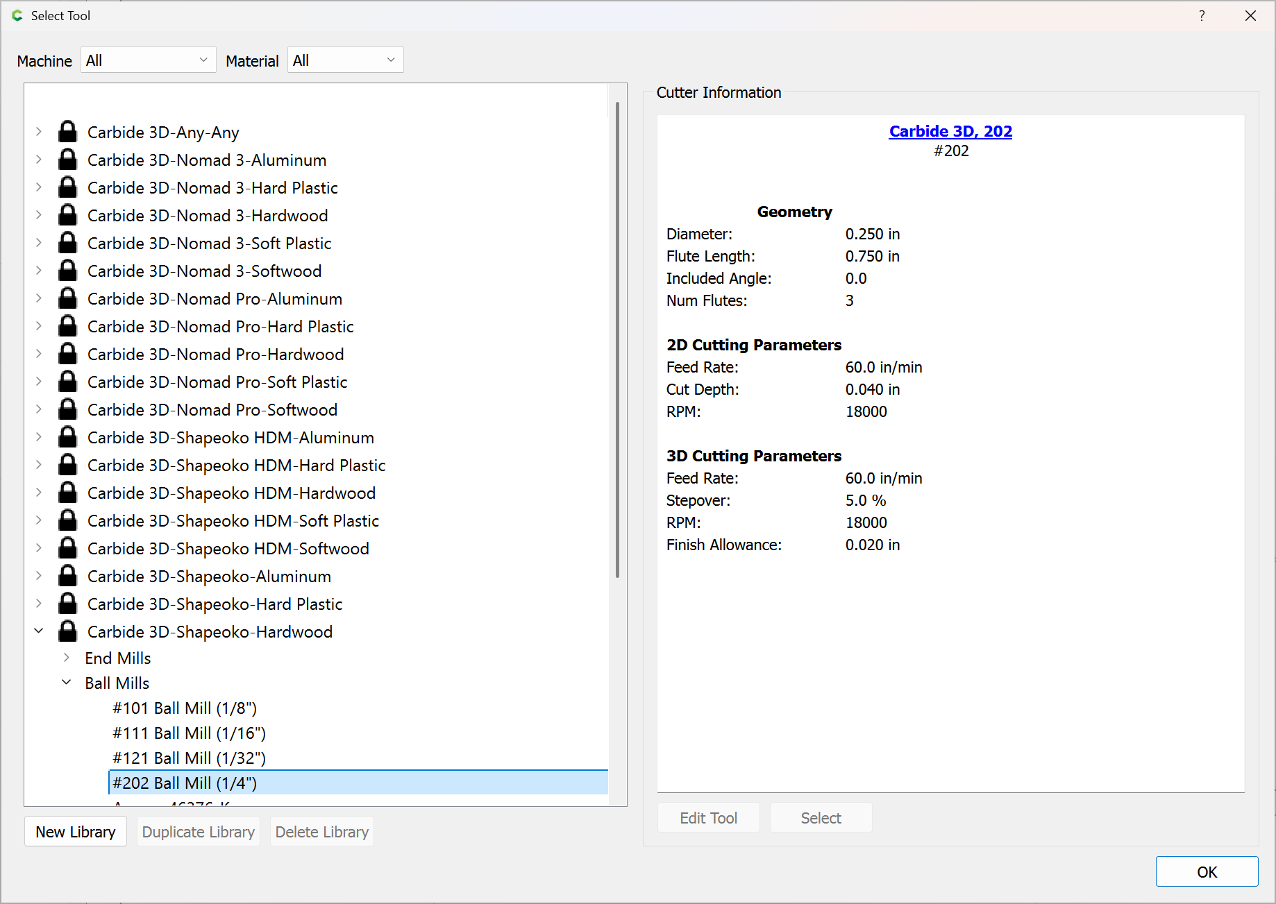
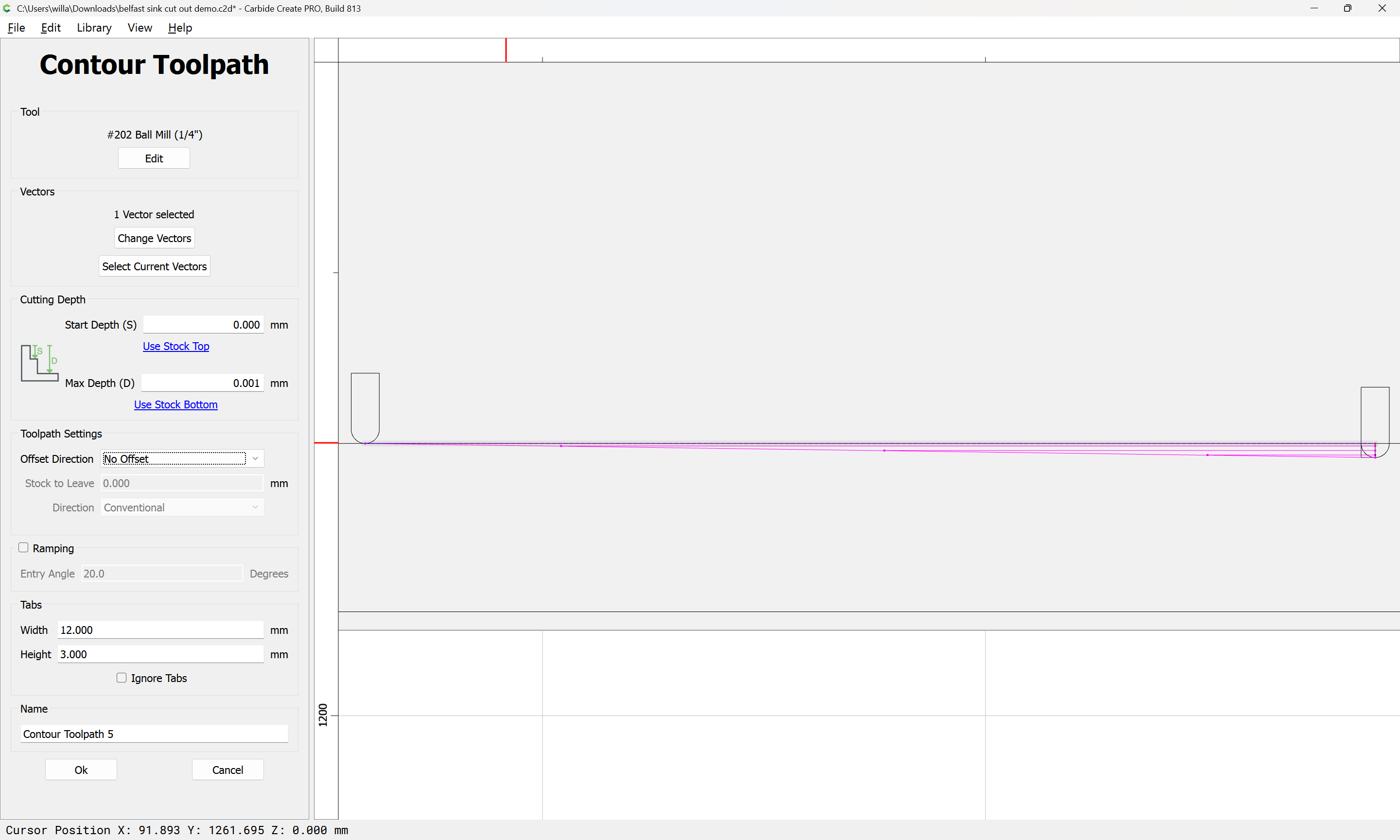
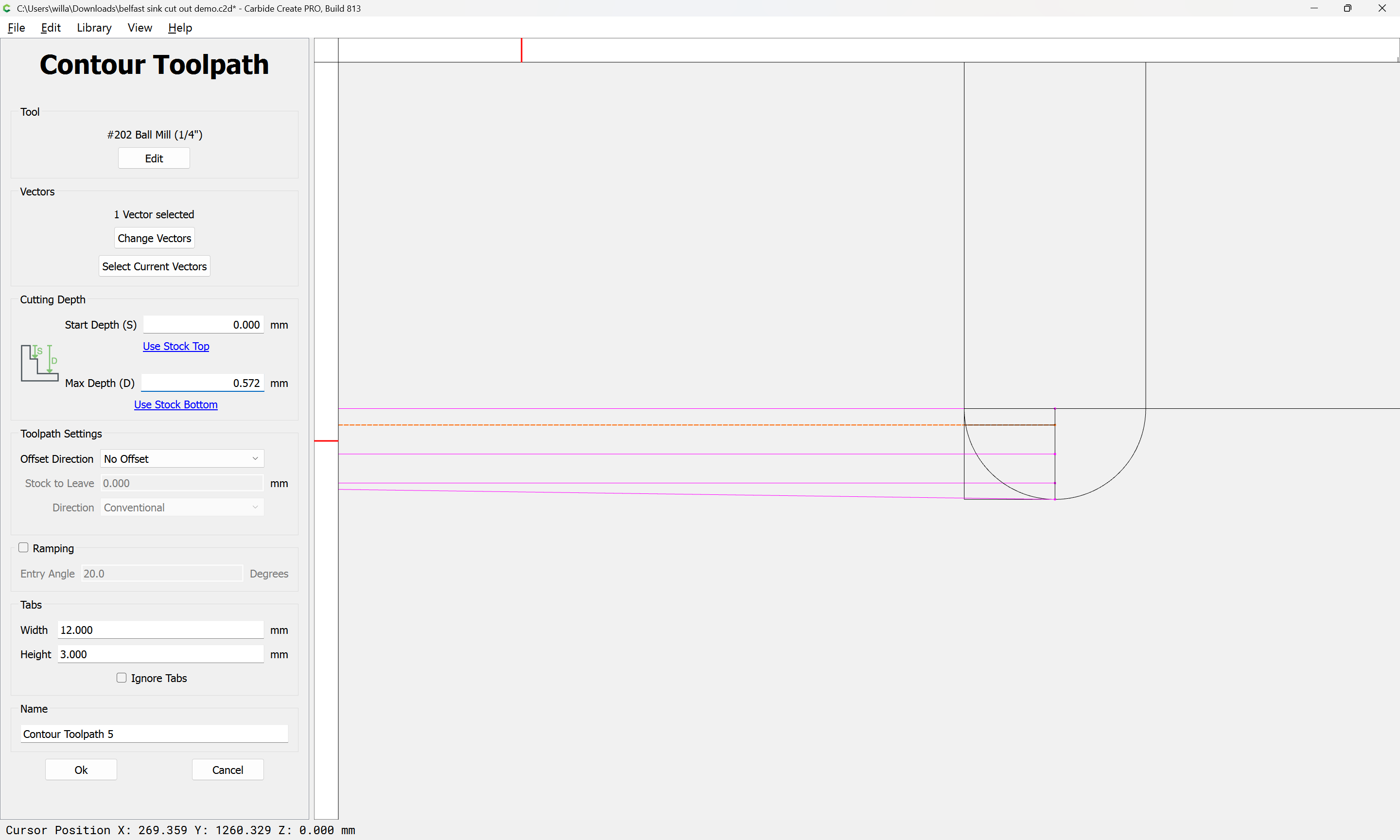
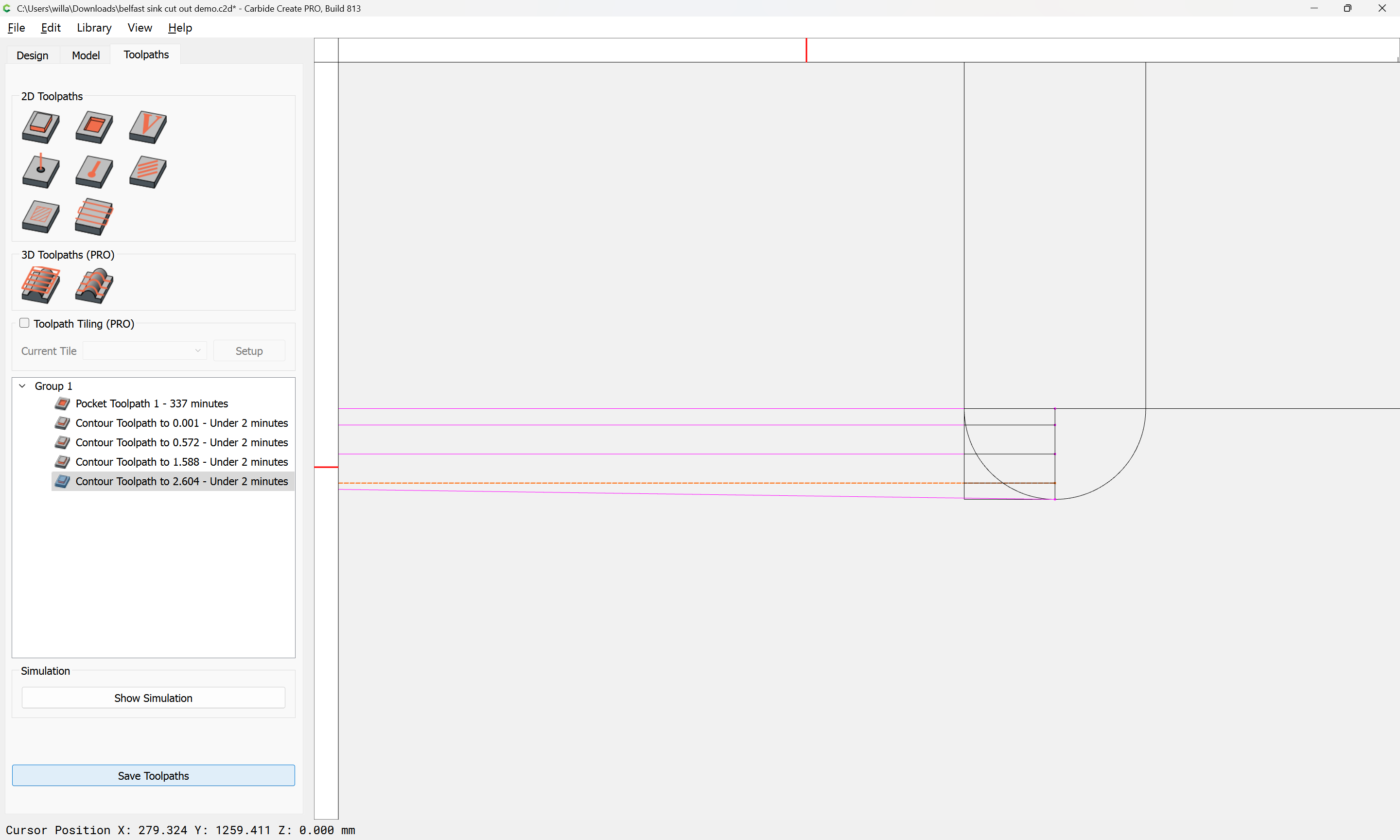
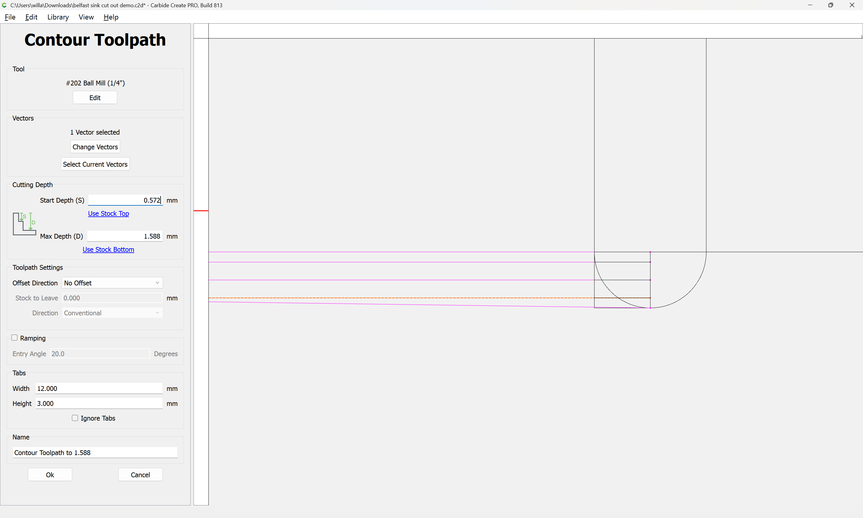
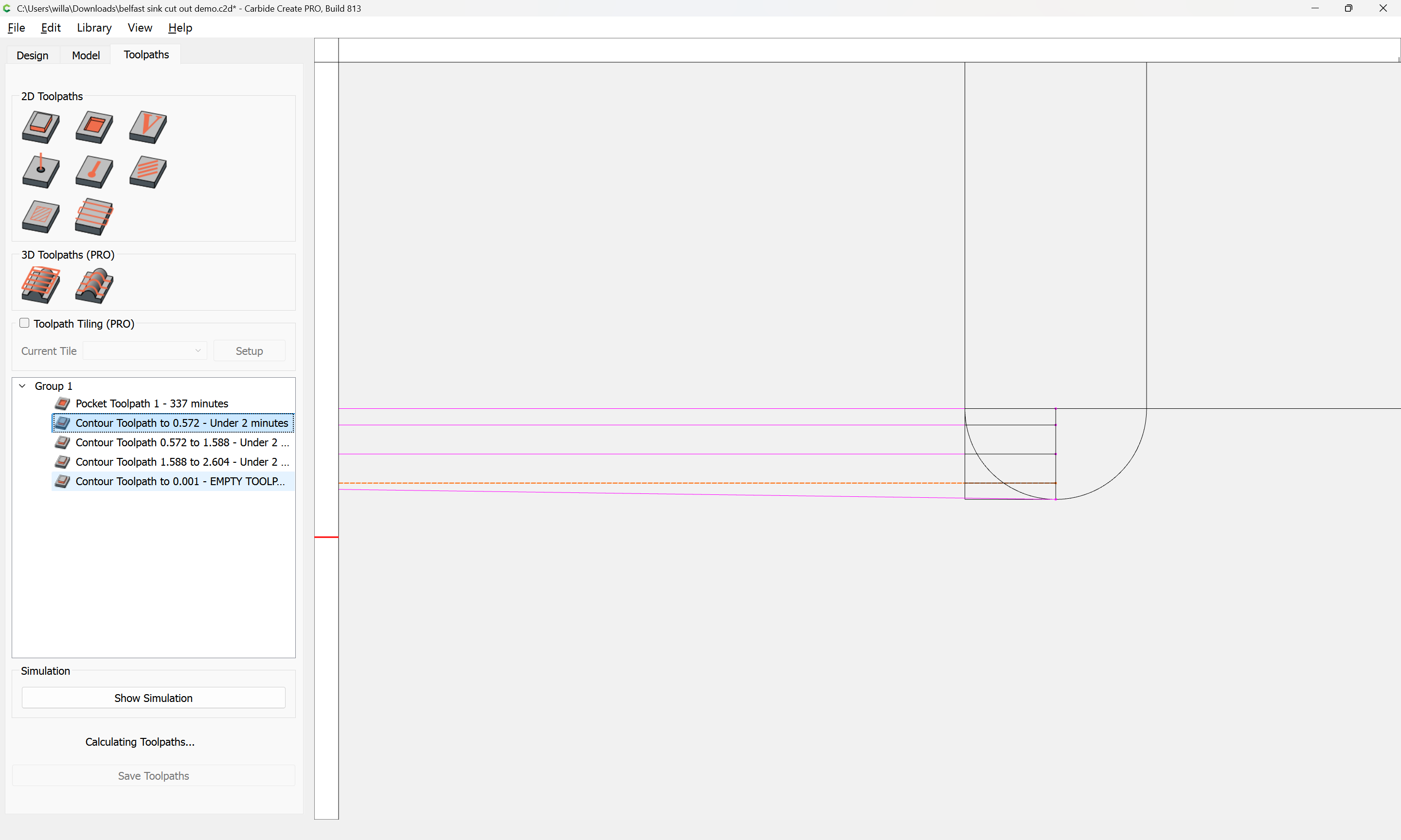
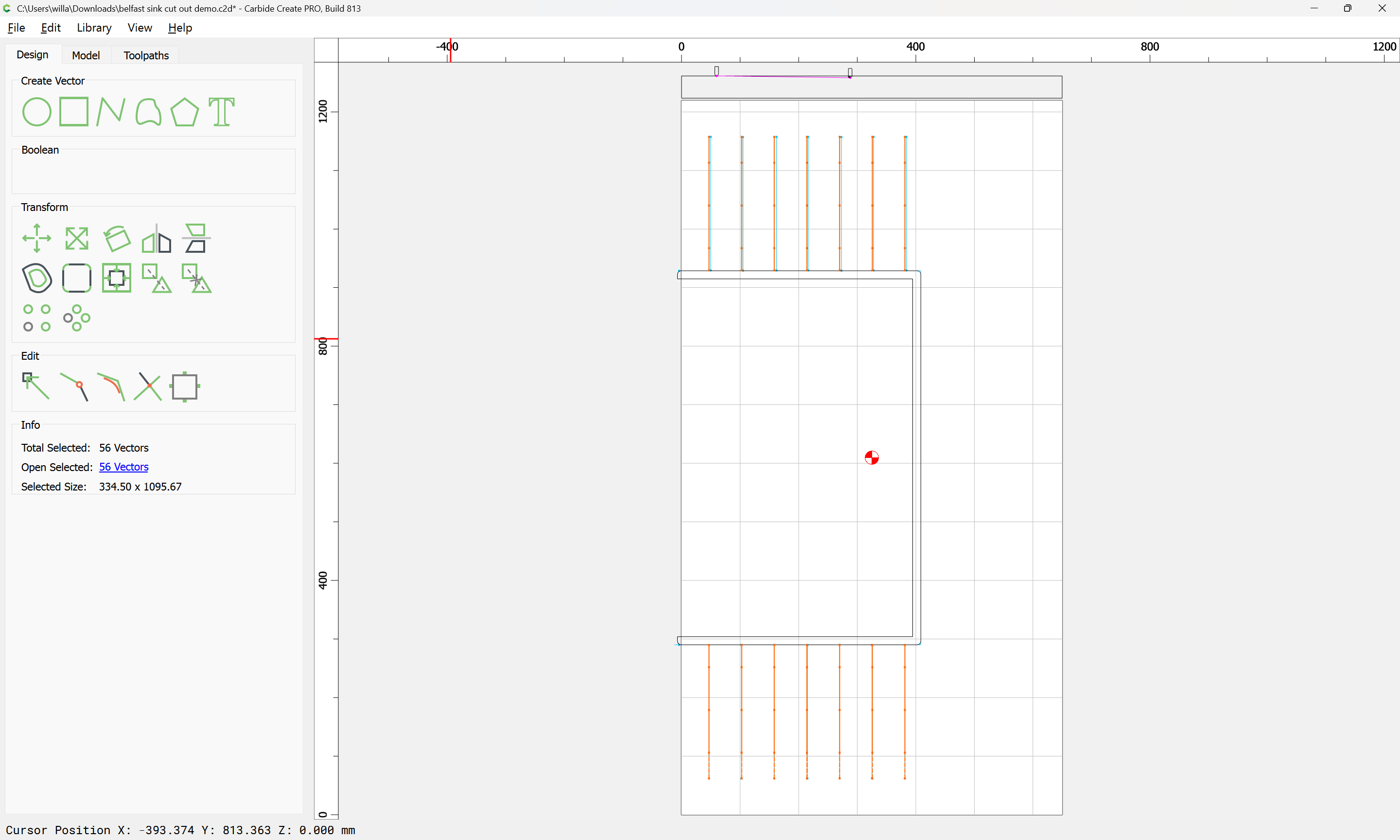
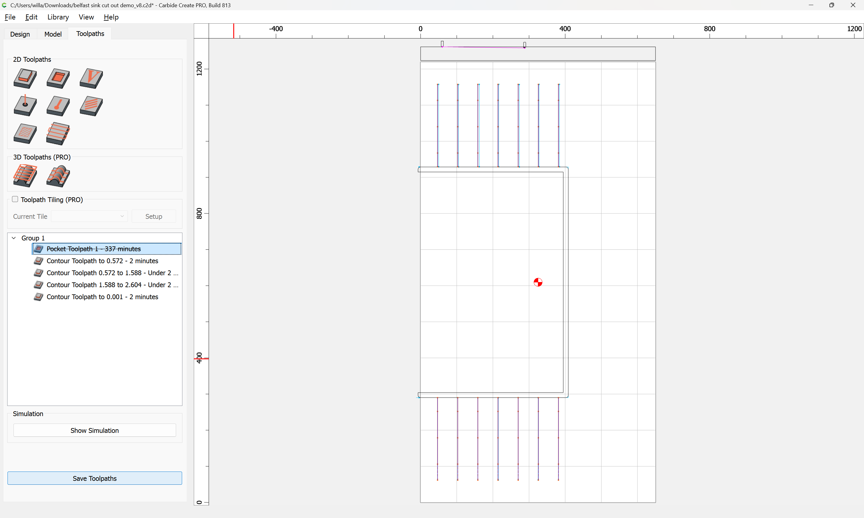
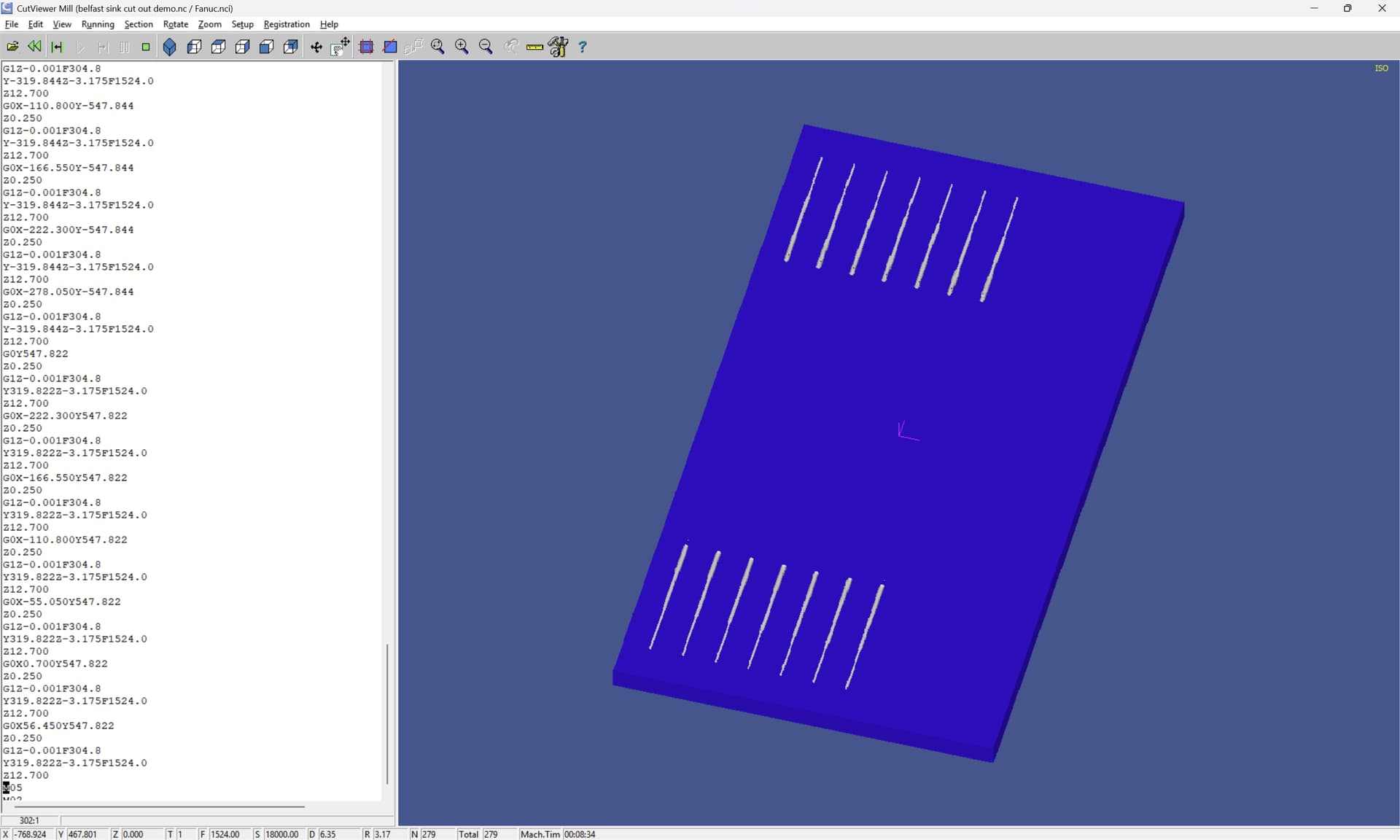
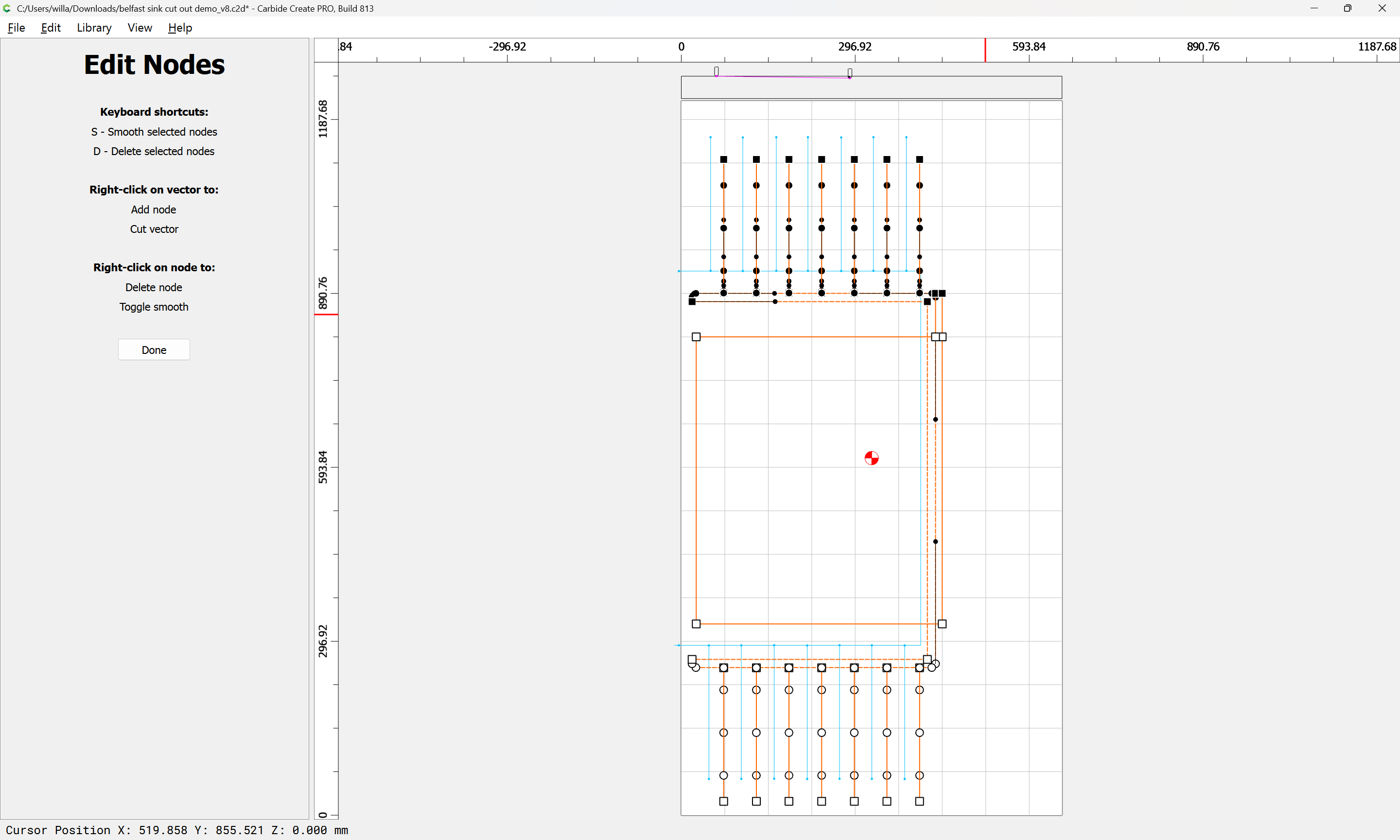
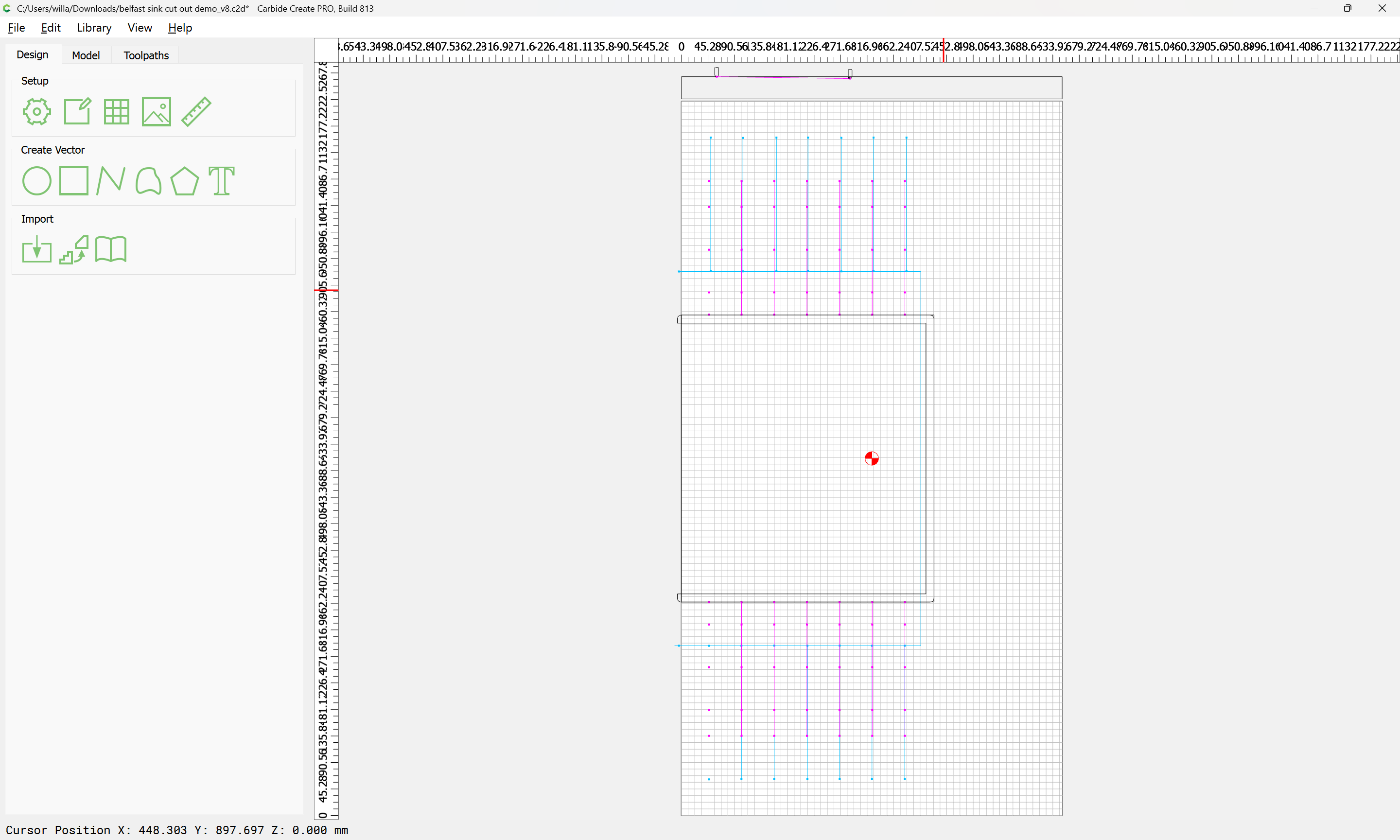
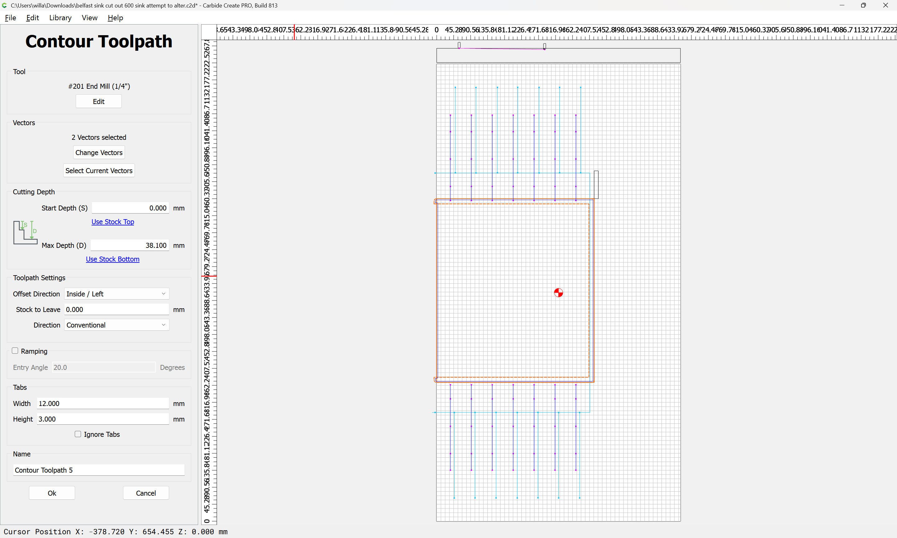
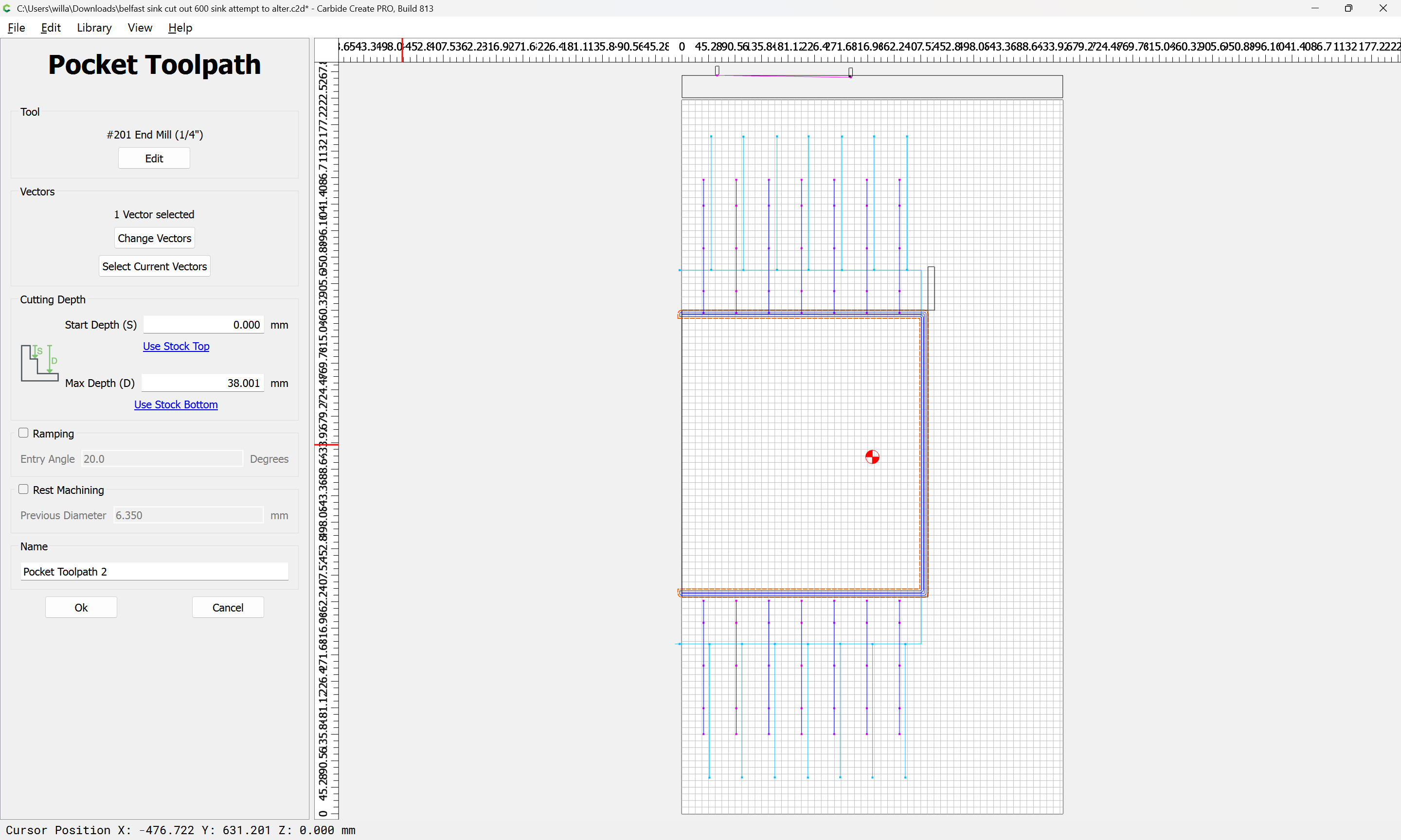
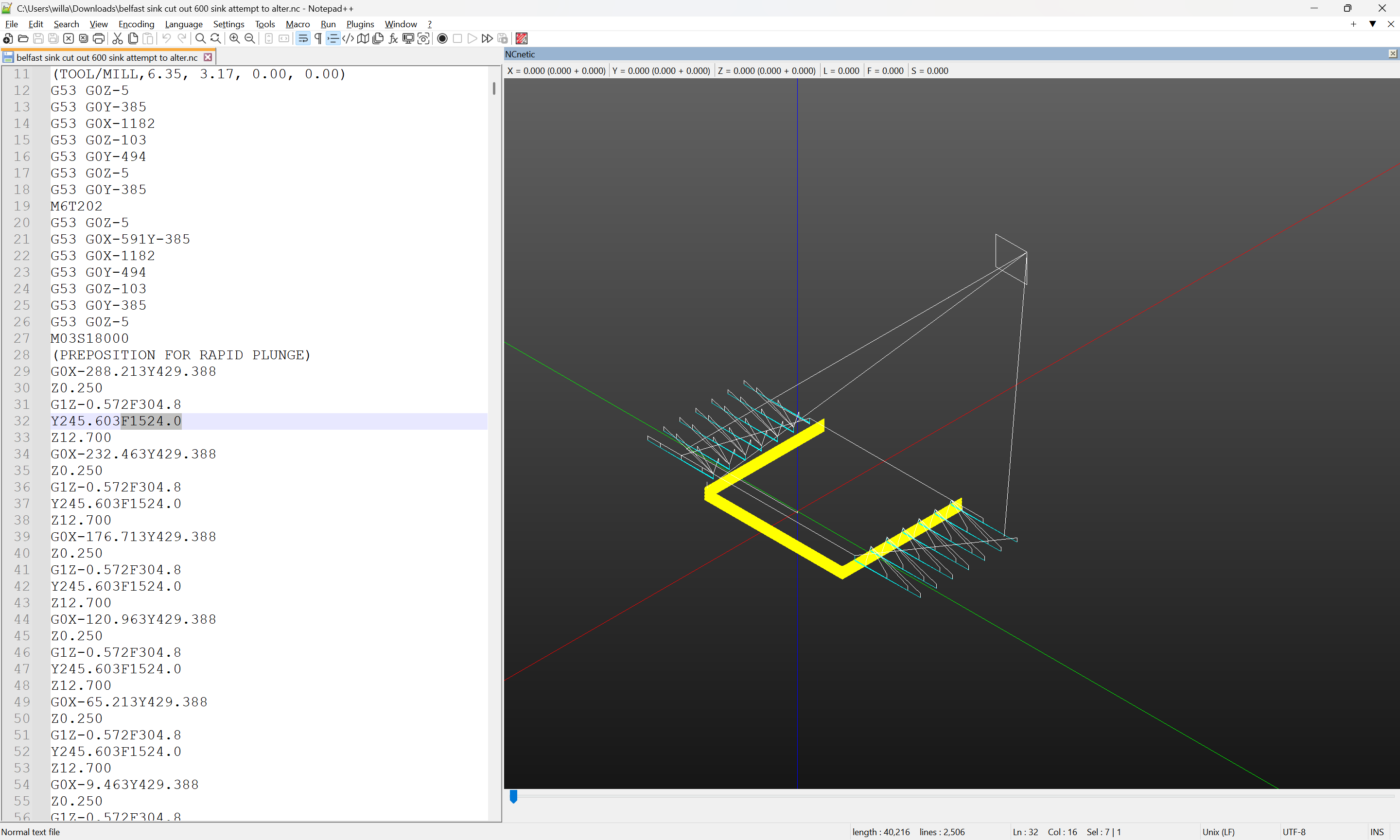
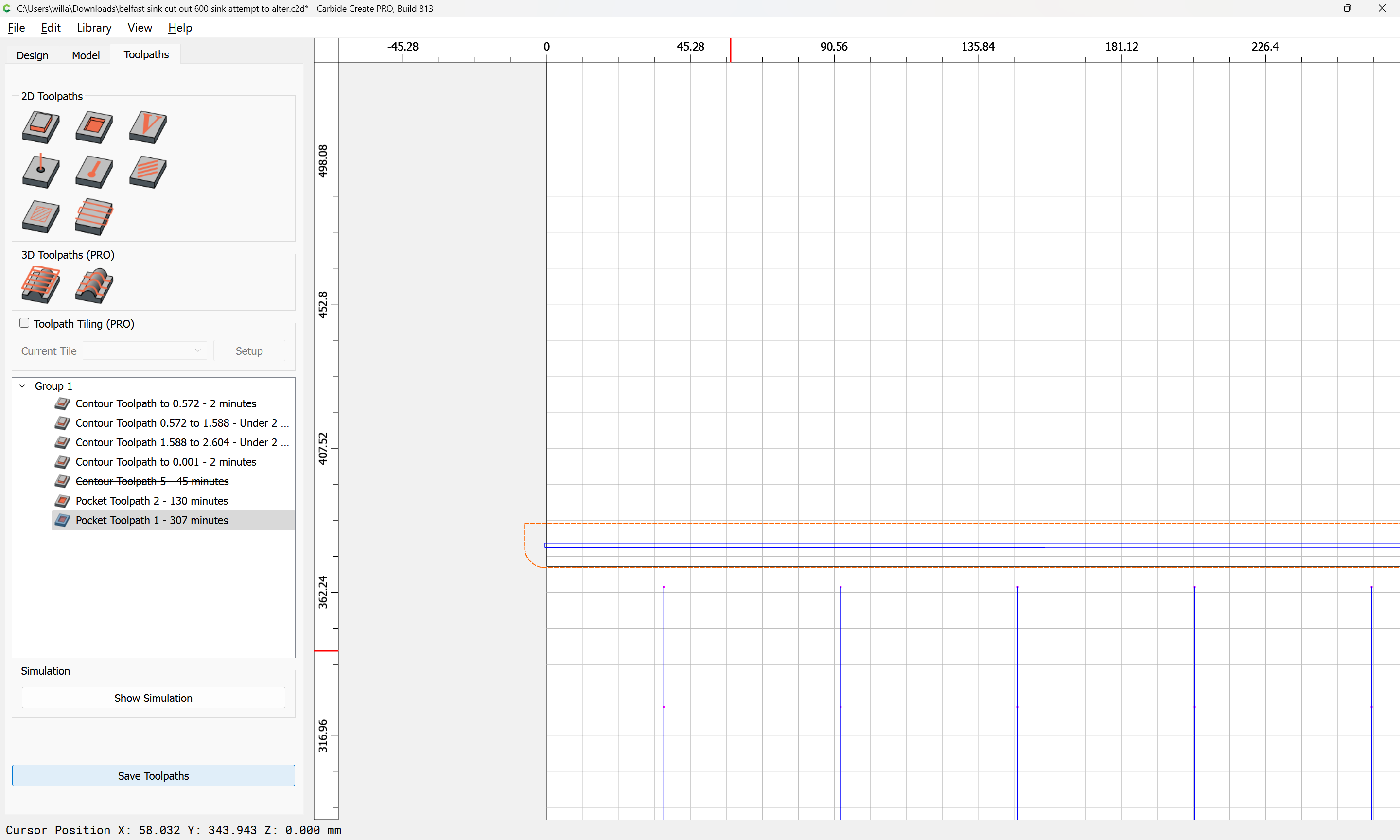
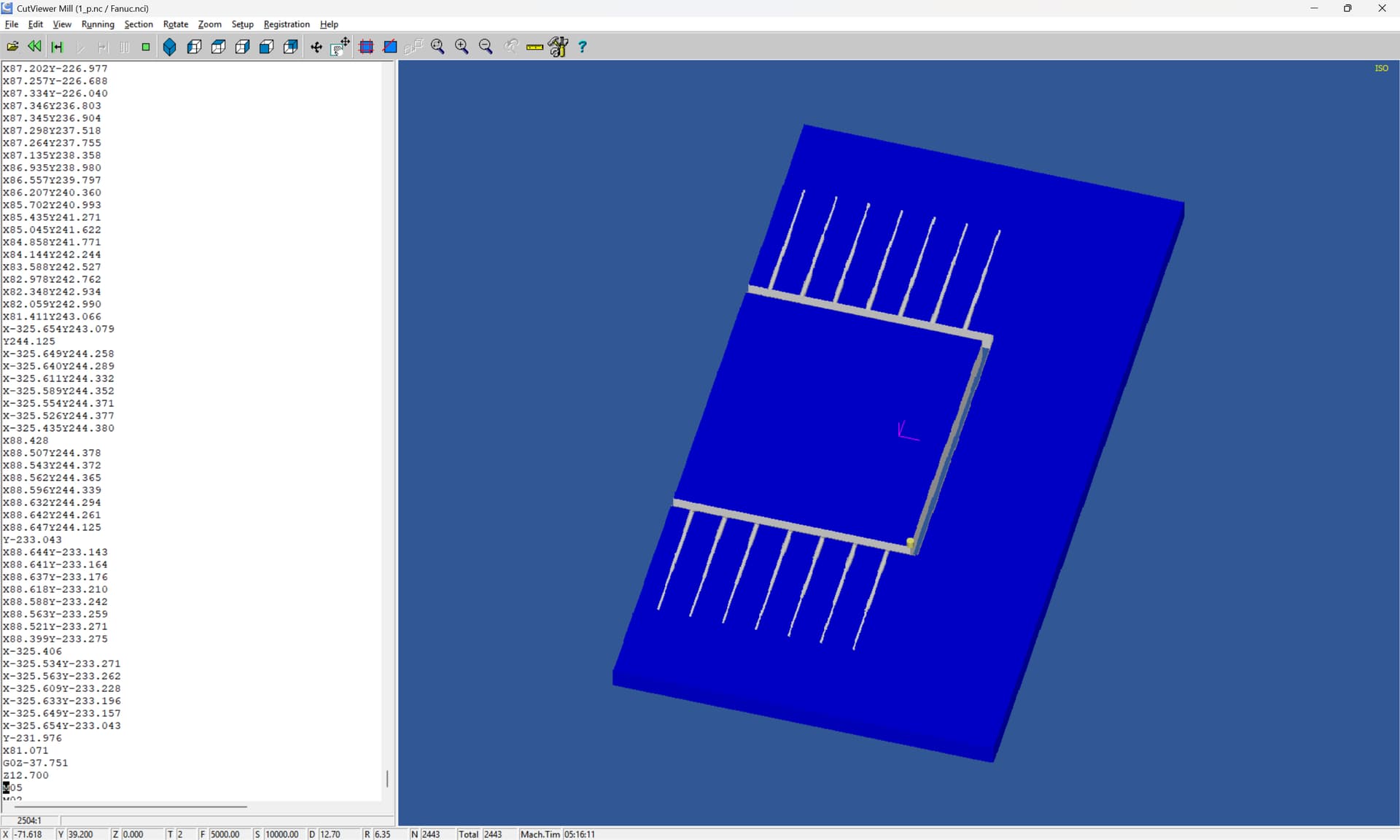
At this point a pocket toolpath w/ a suitable tool may be assigned to make the opening cut:
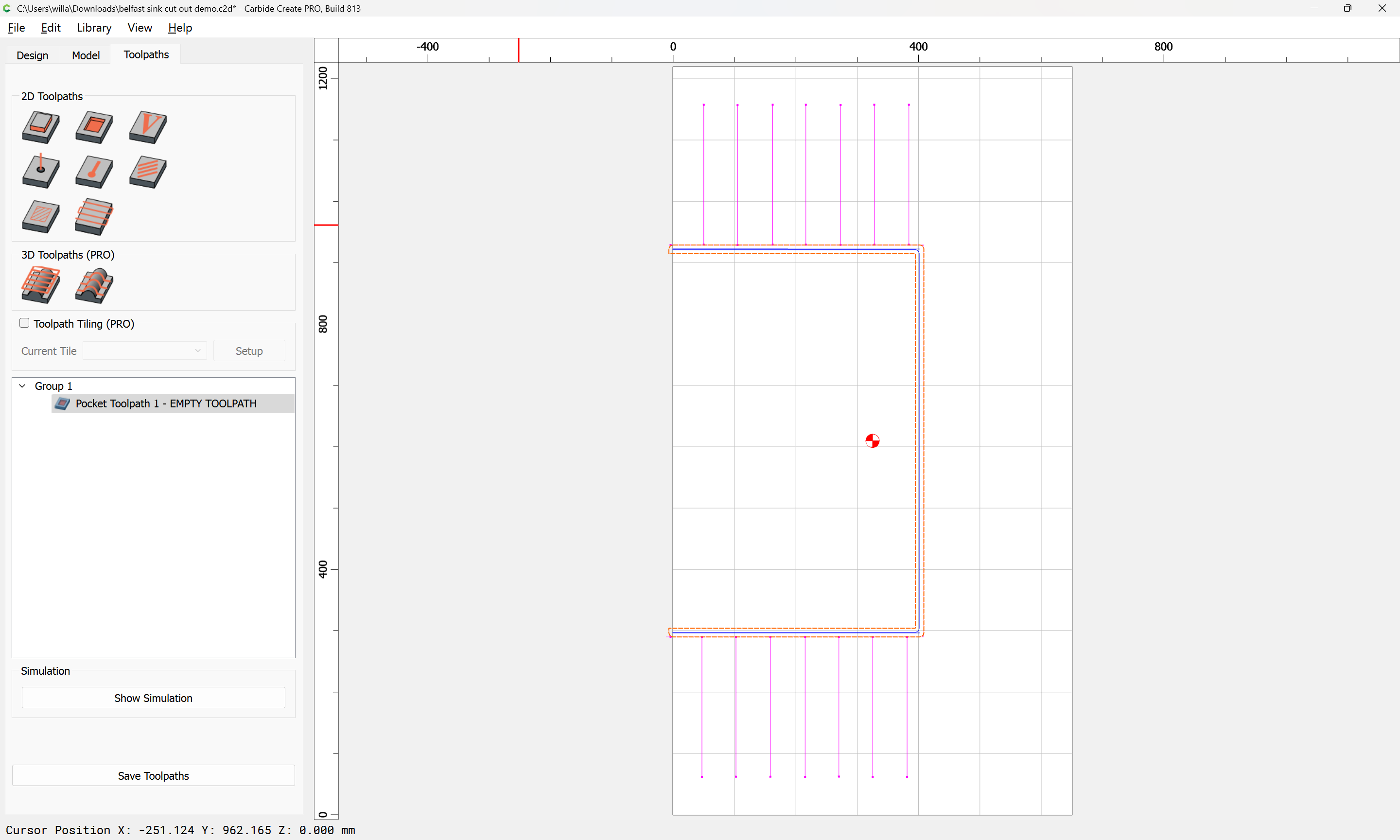
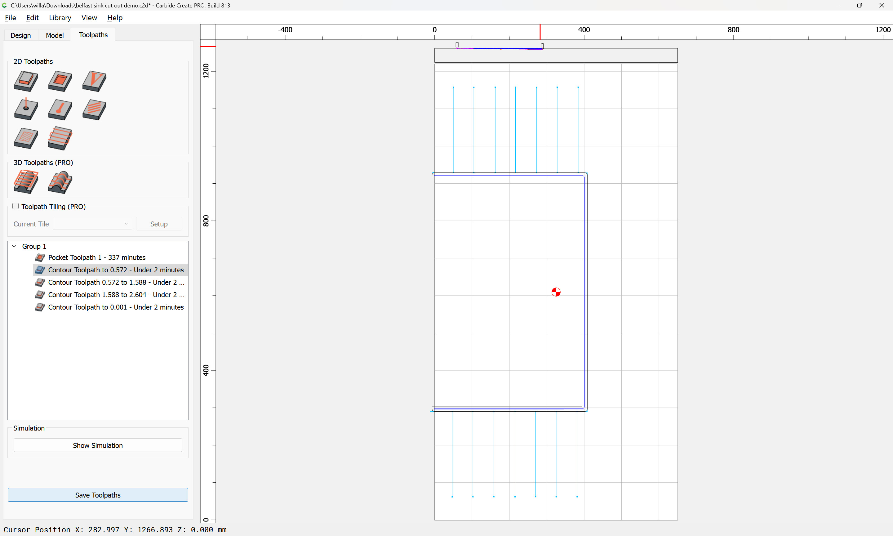
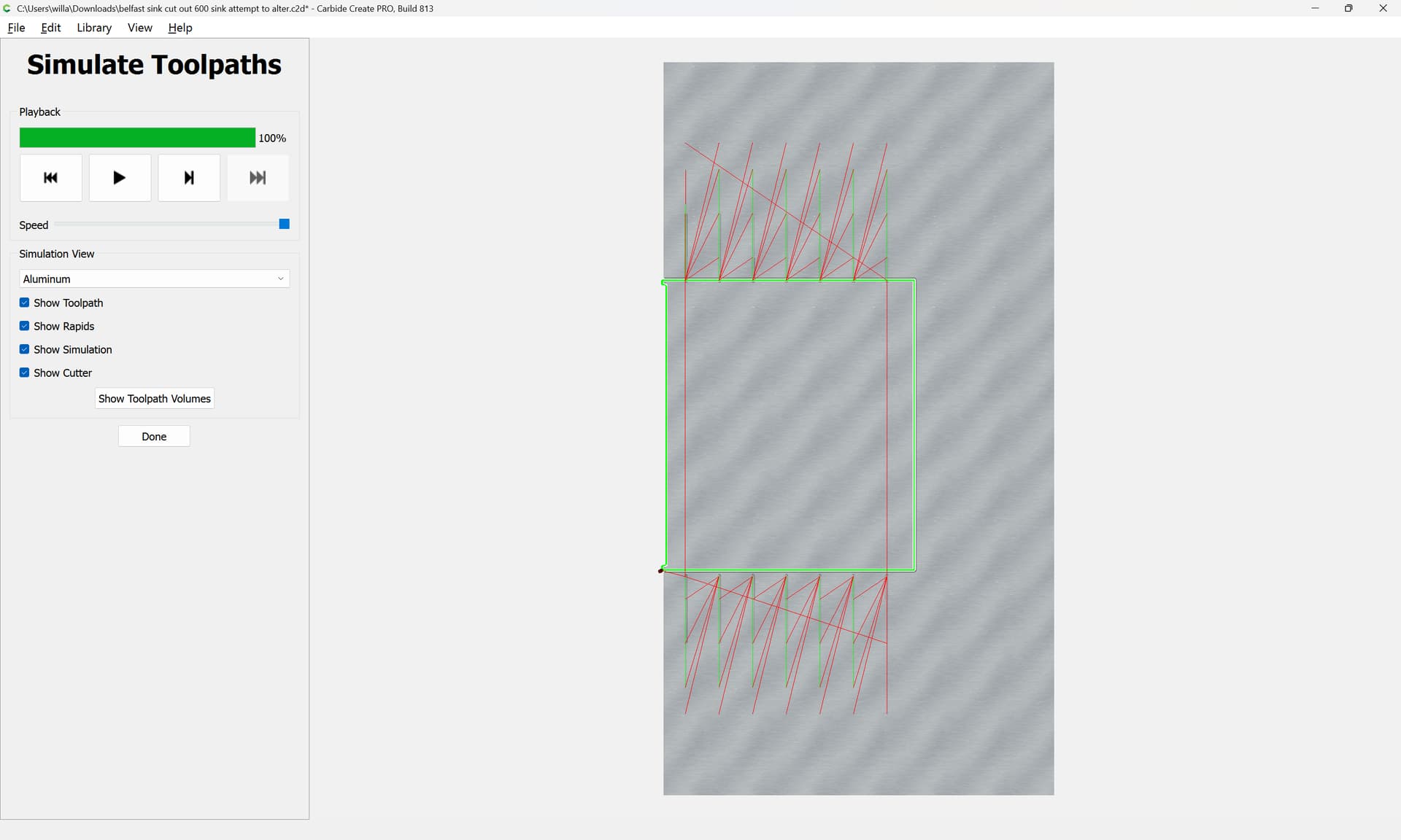
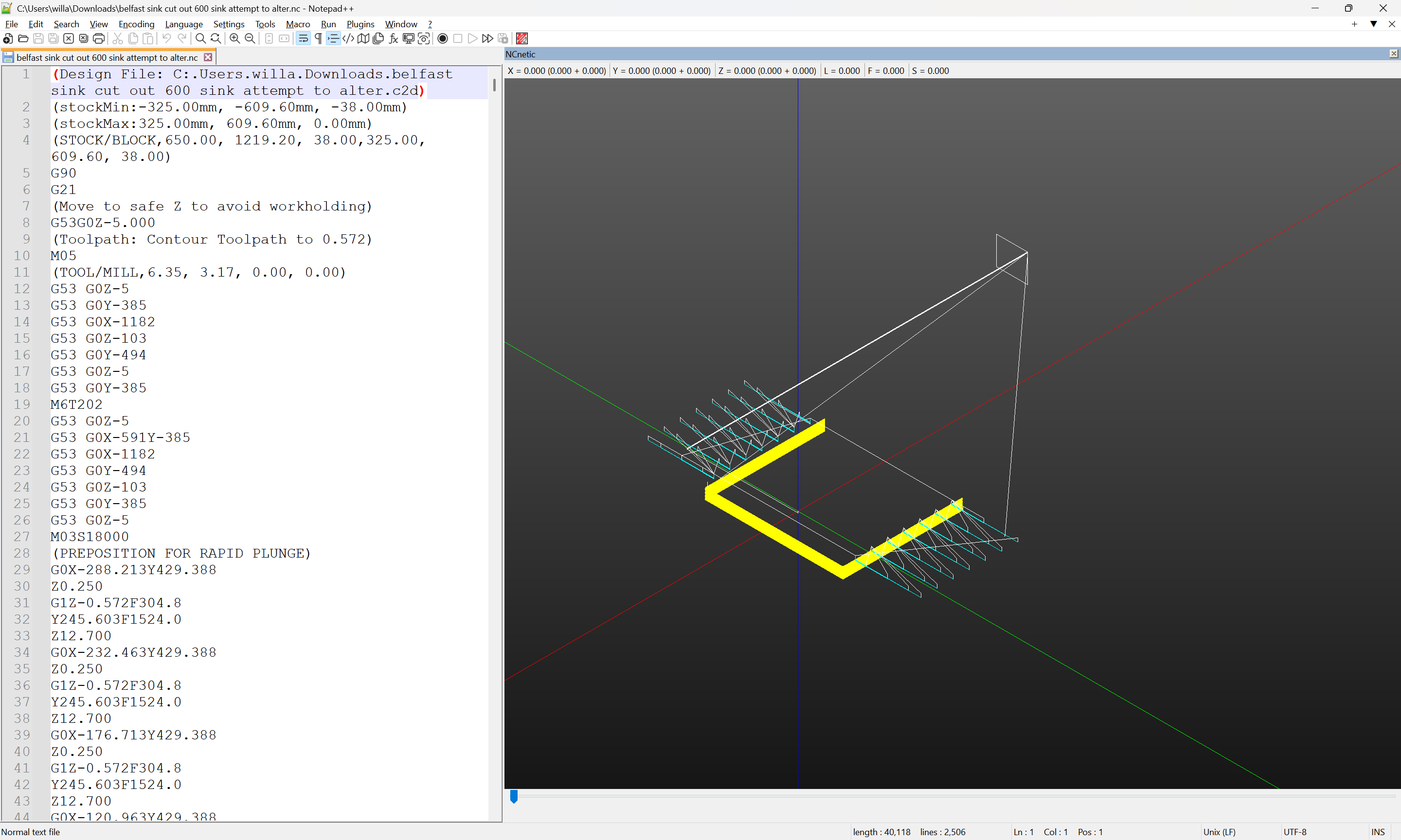
which previews as:
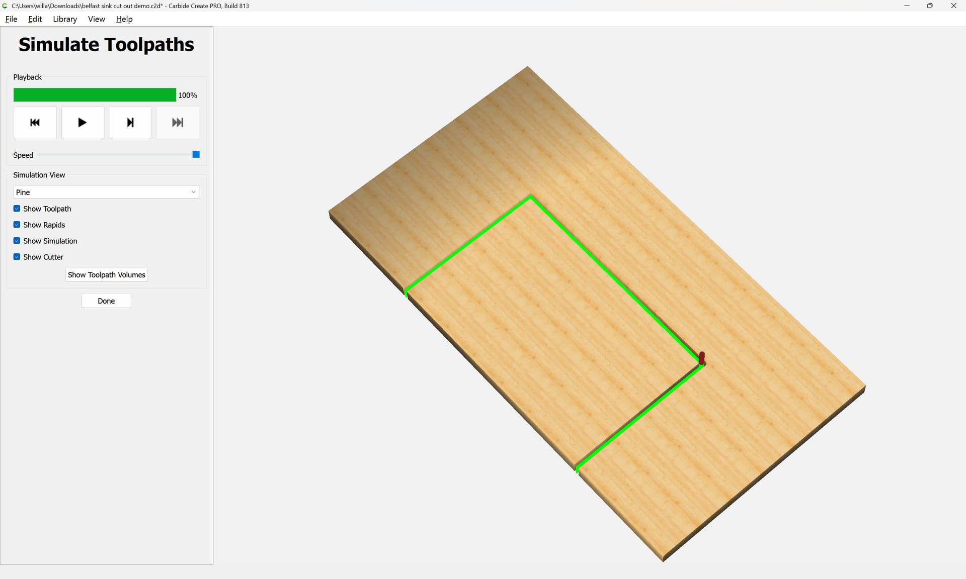
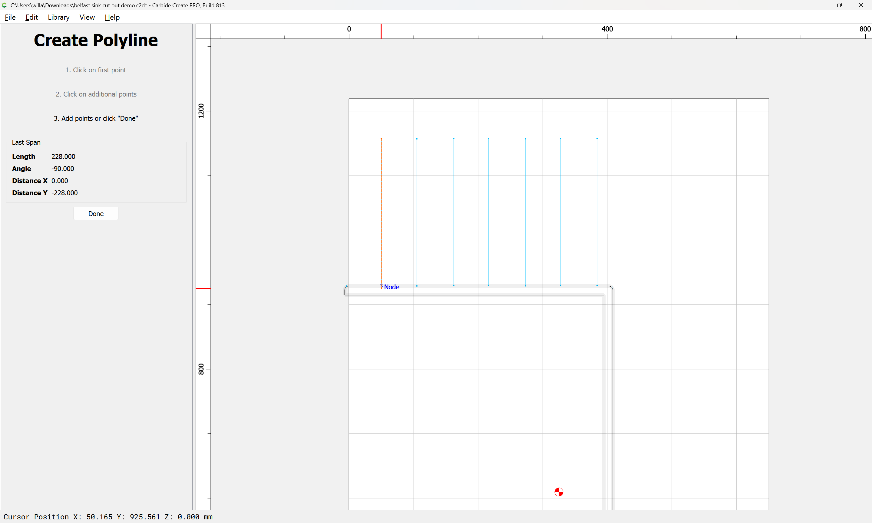
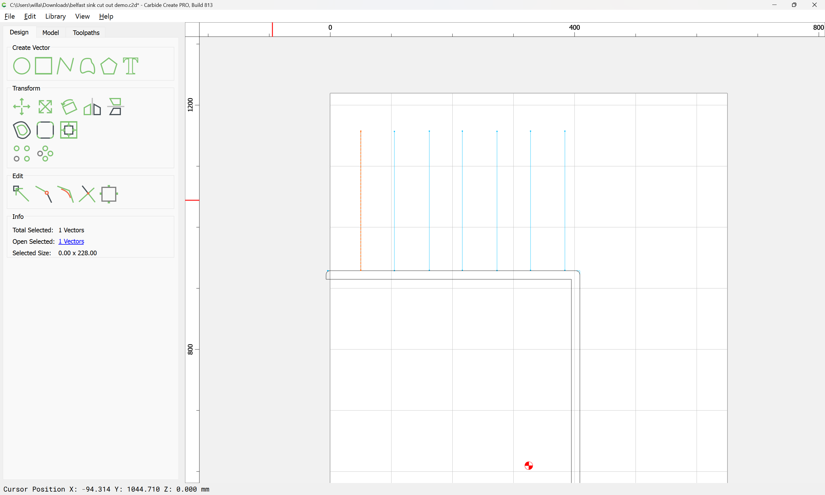
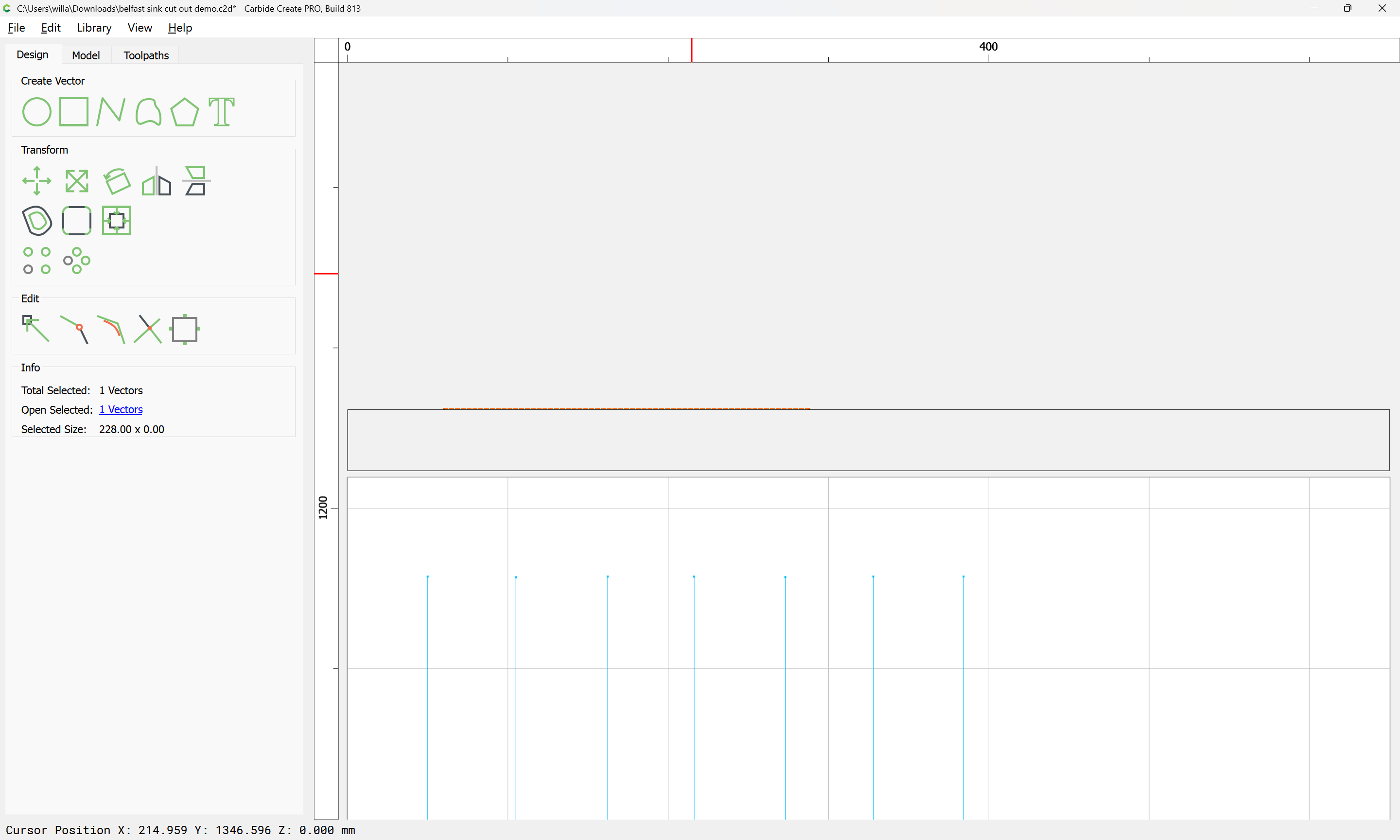
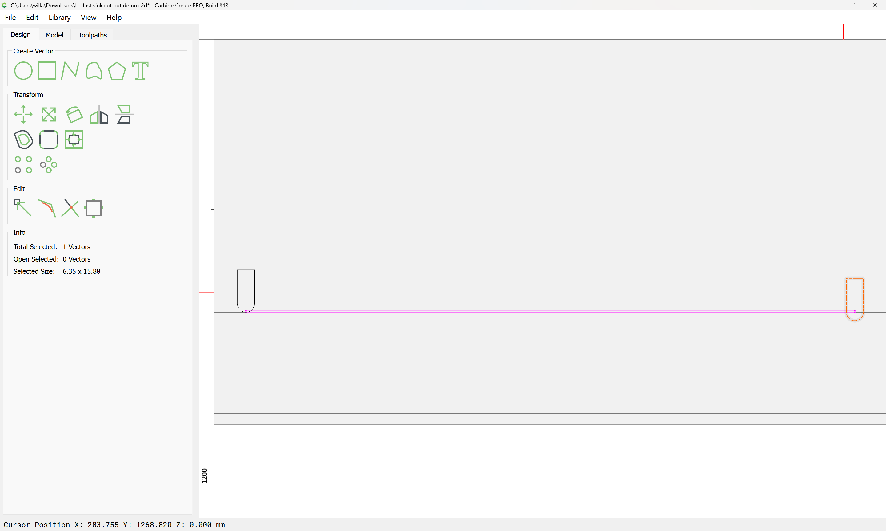
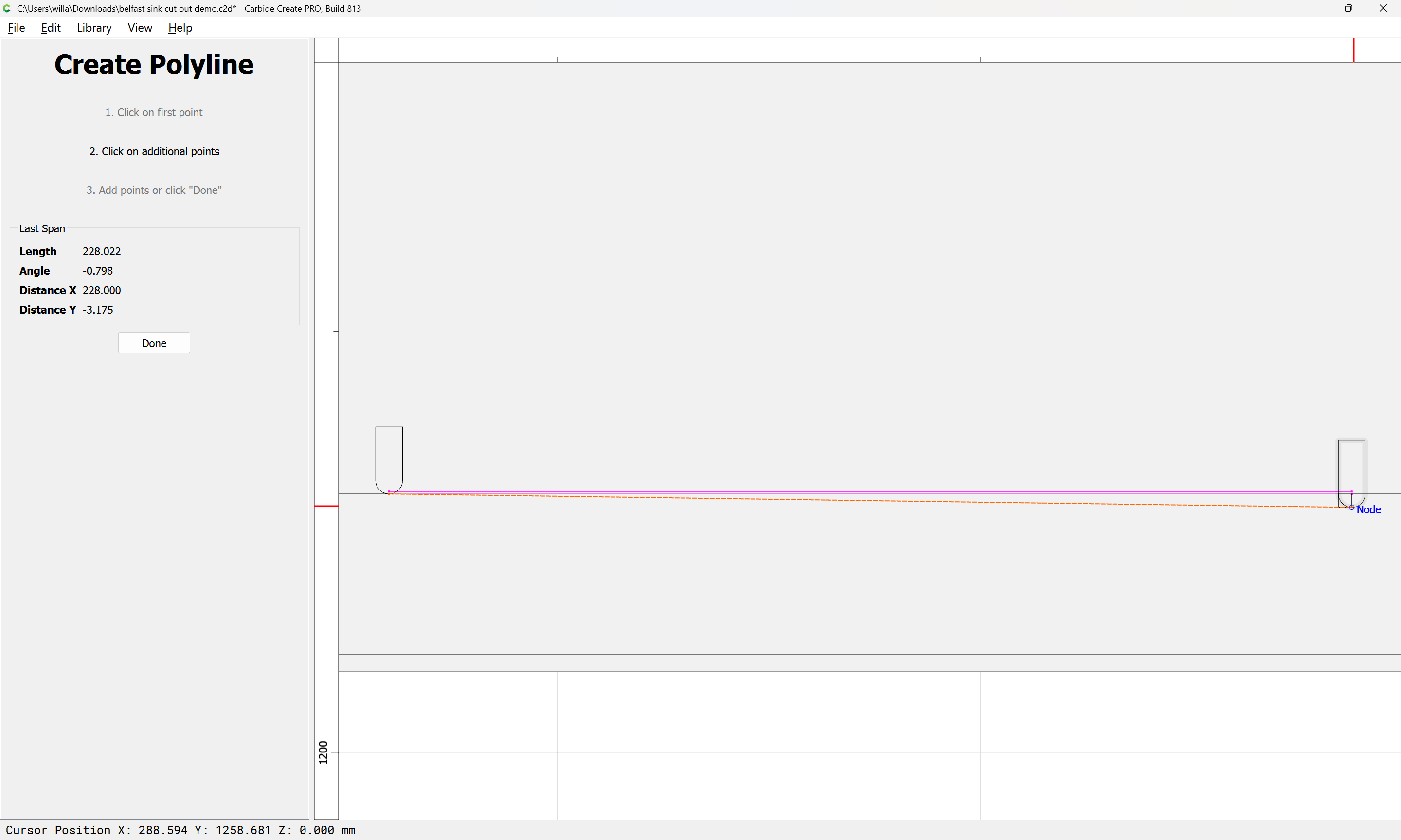
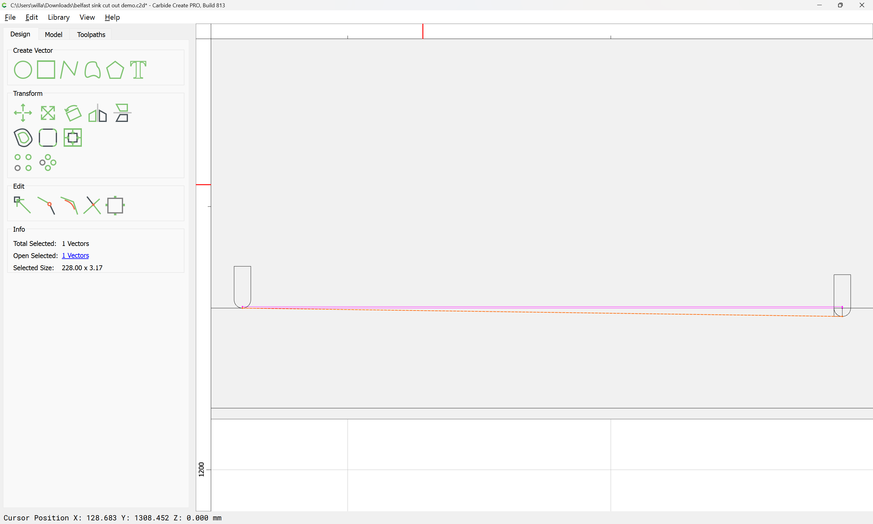
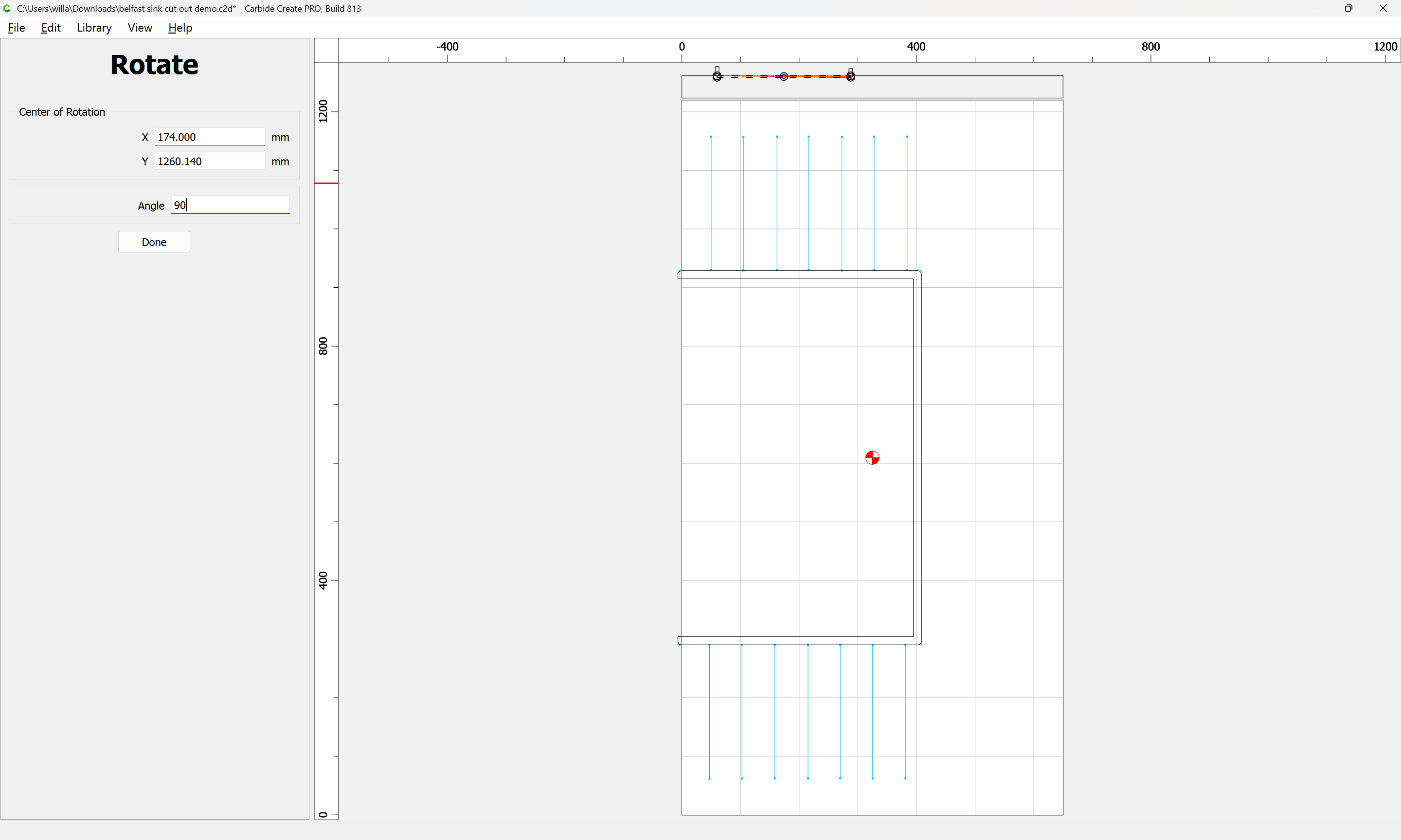
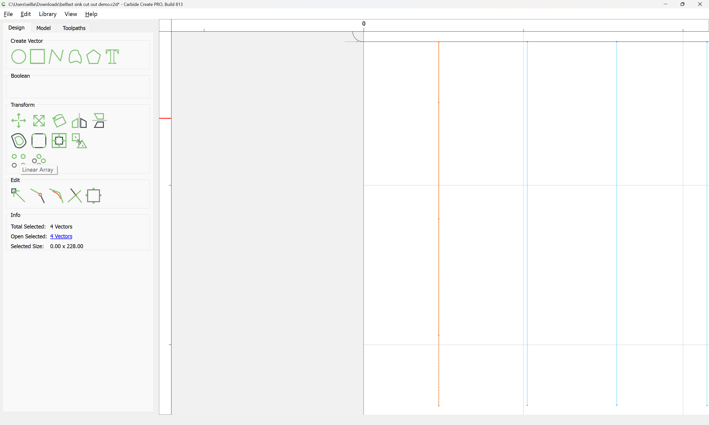
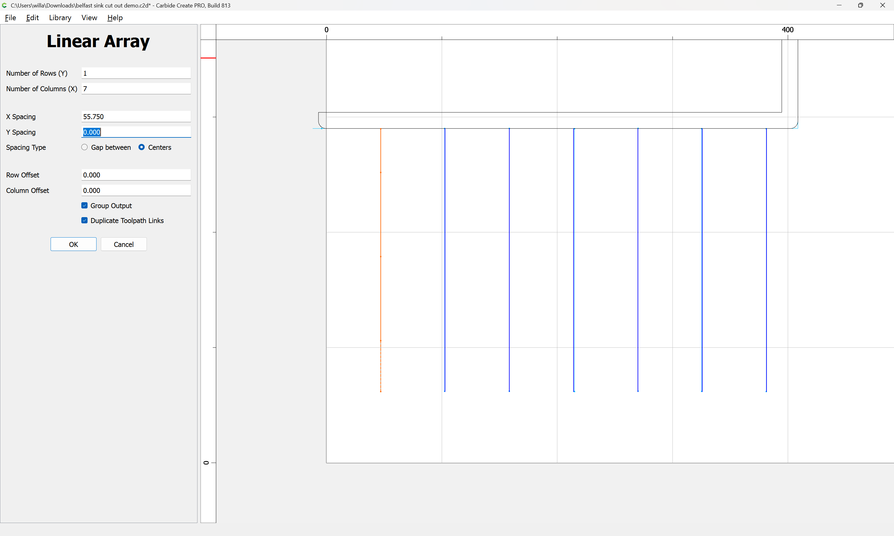
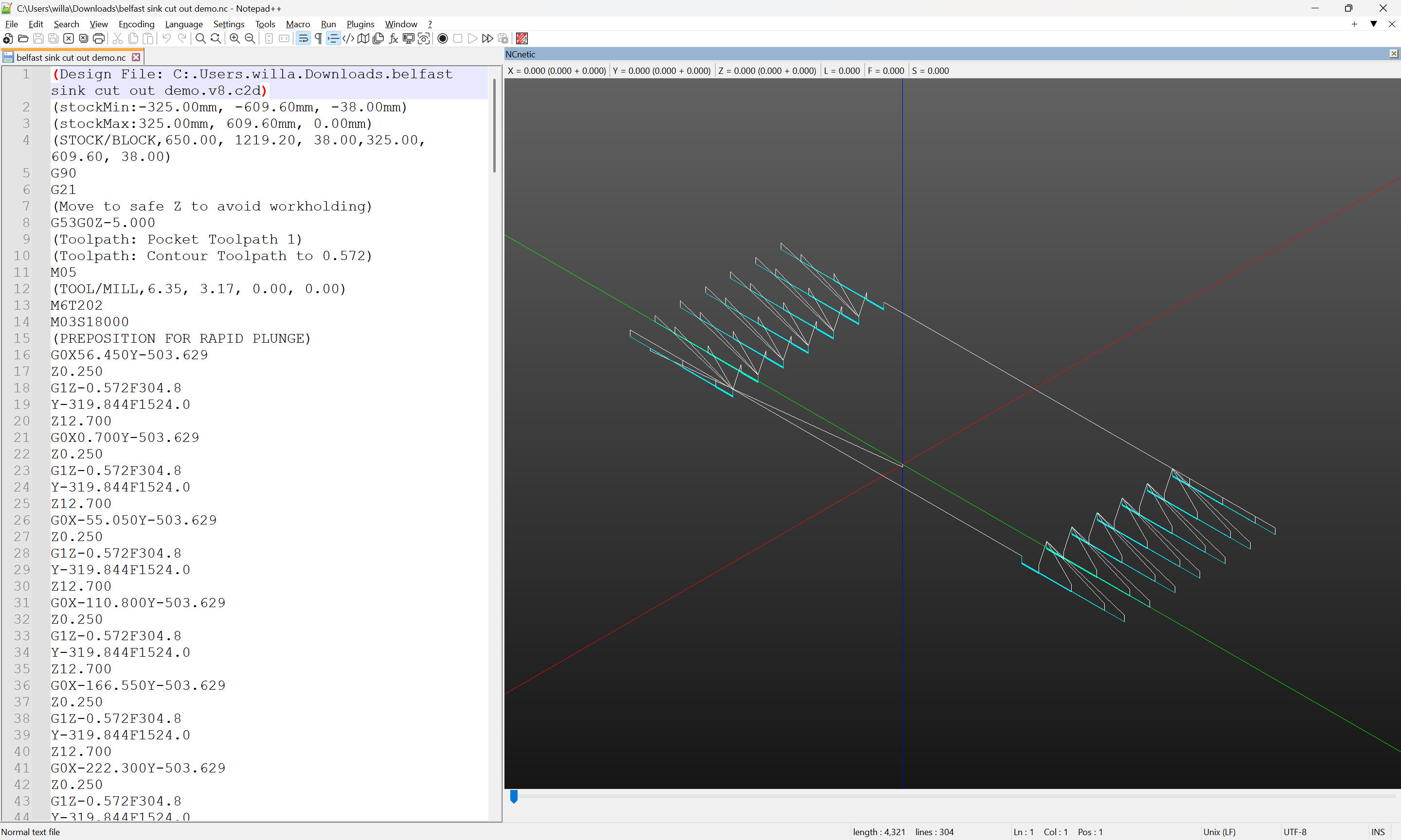
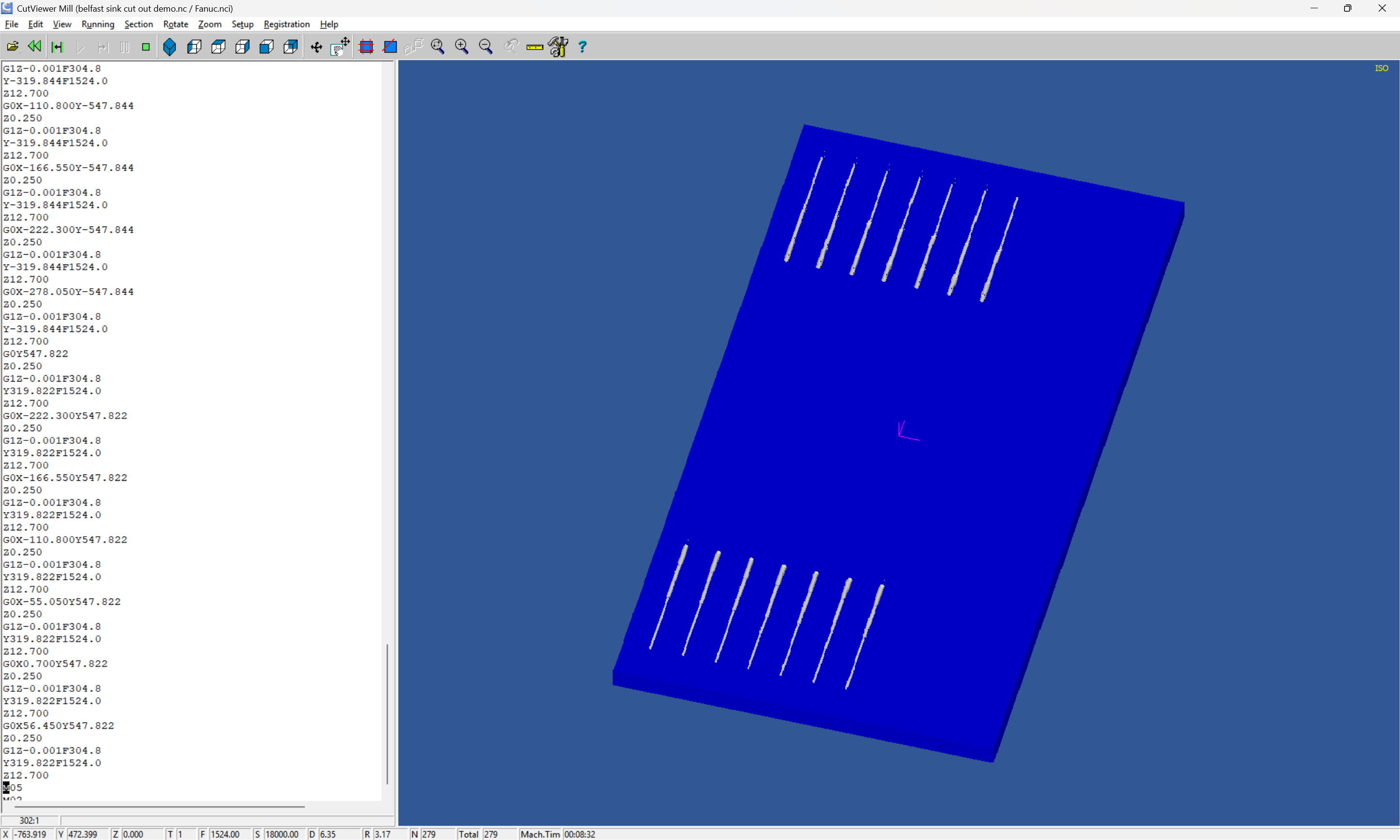
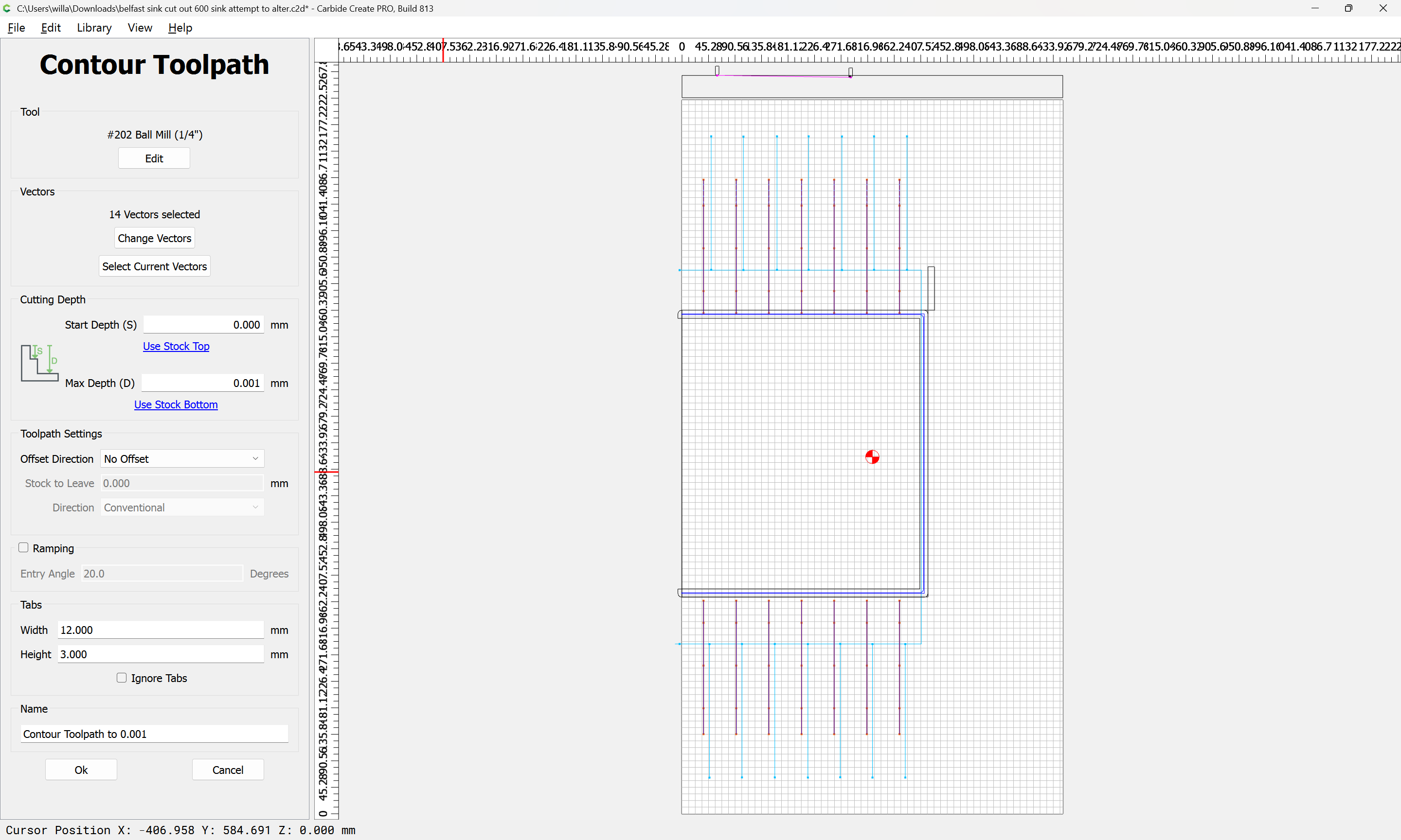
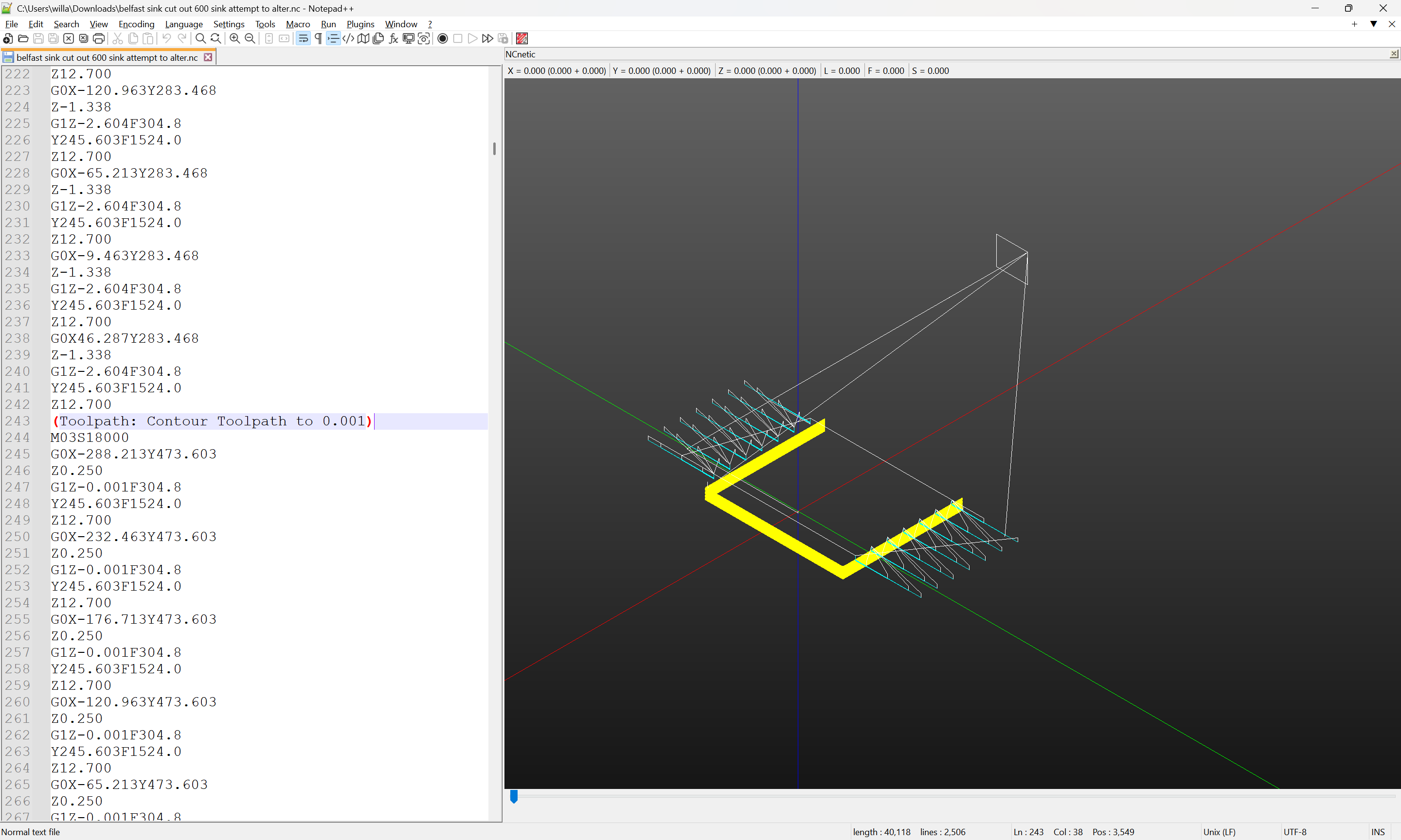
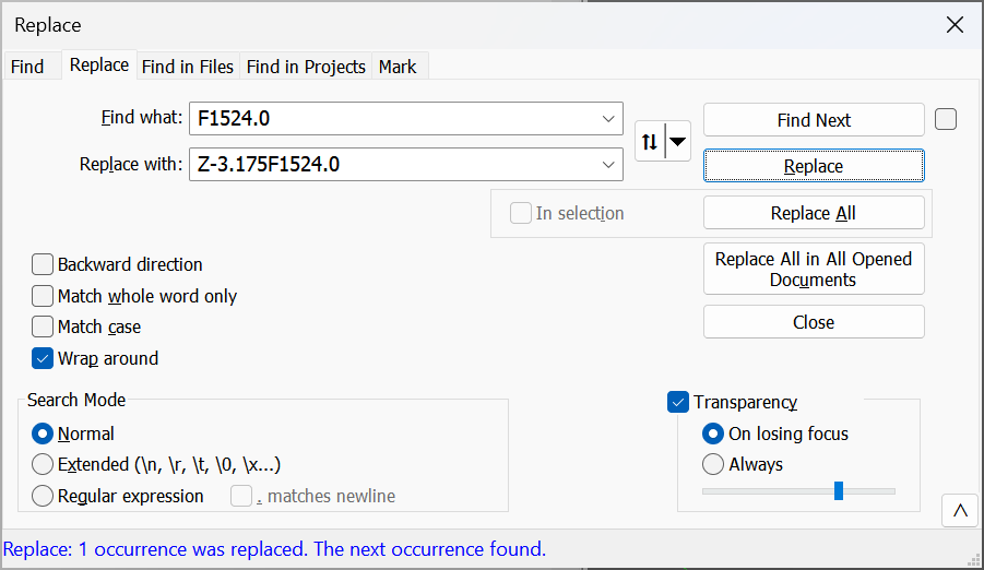
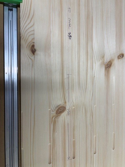
Next, for the grooves, this will be done as a series of short straight lines for the initial cut, then a finishing pass will be made using hand-edited G-code.