WillAdams
December 11, 2023, 12:19am
1
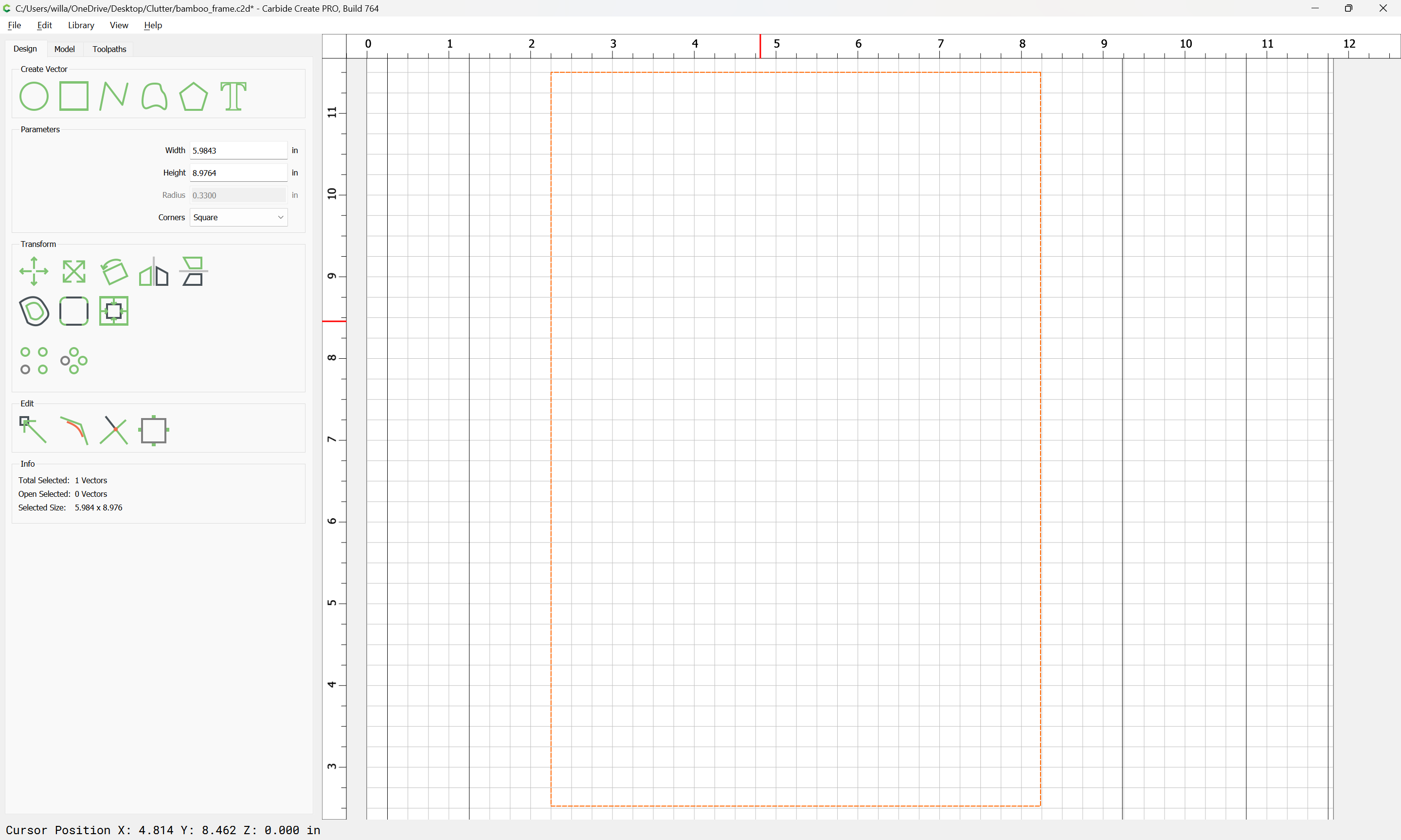
Given the need to create a frame for a piece of art which is roughly 152 x 228mm:
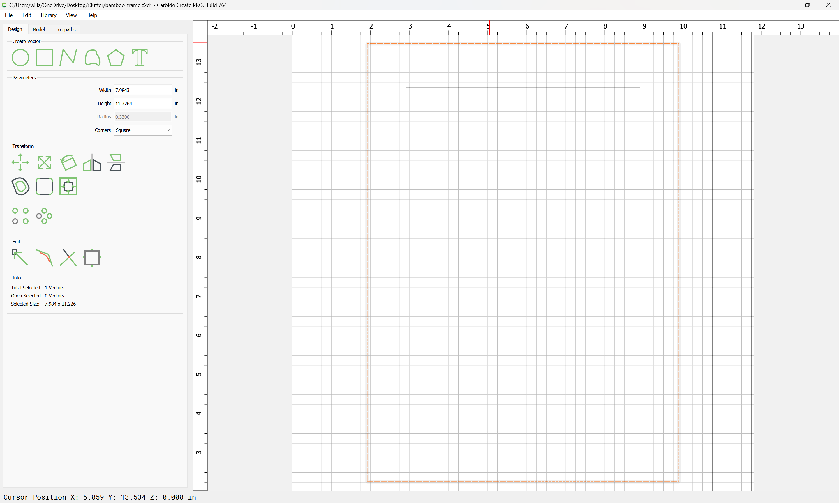
we add an inch around the sides and a bit more at the bottom for a mat:
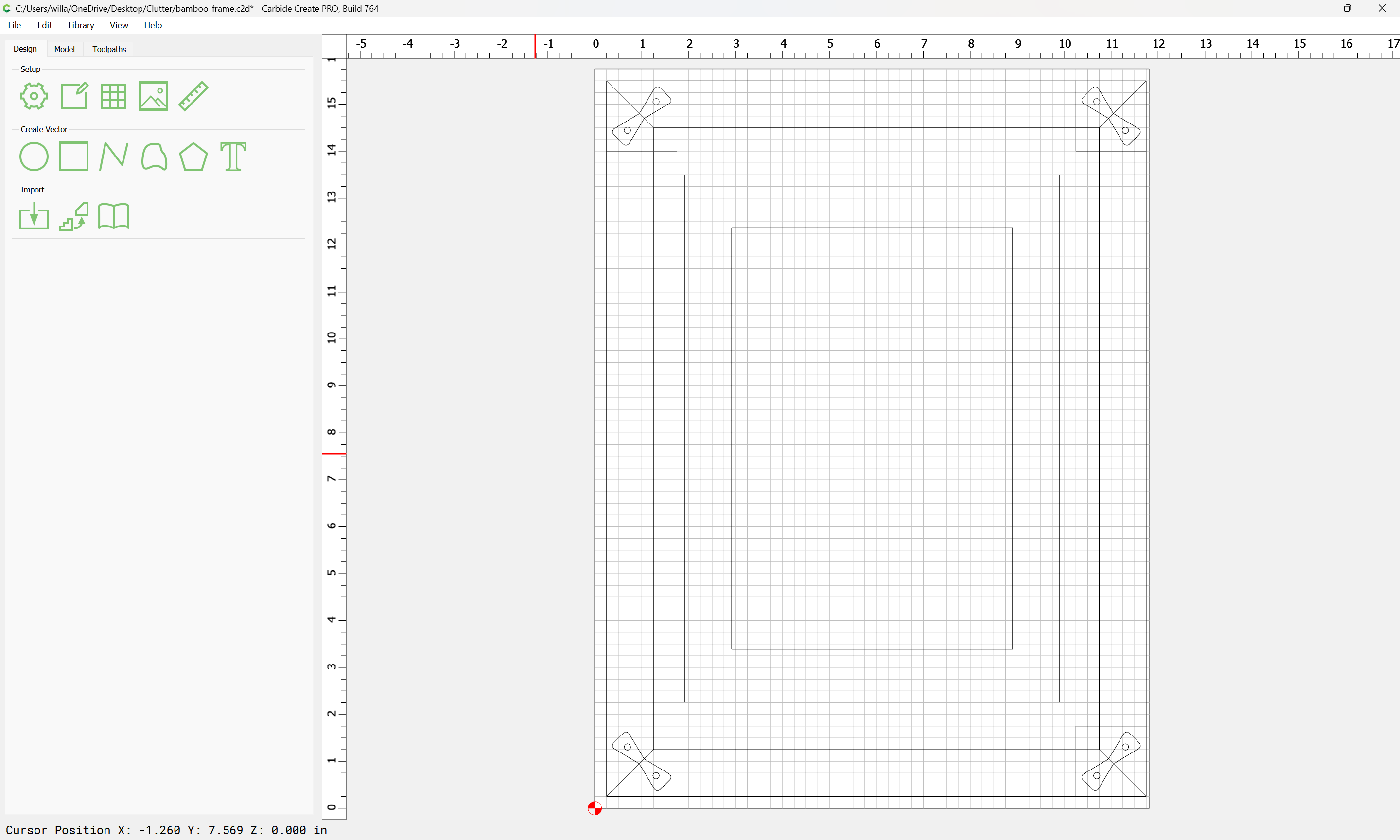
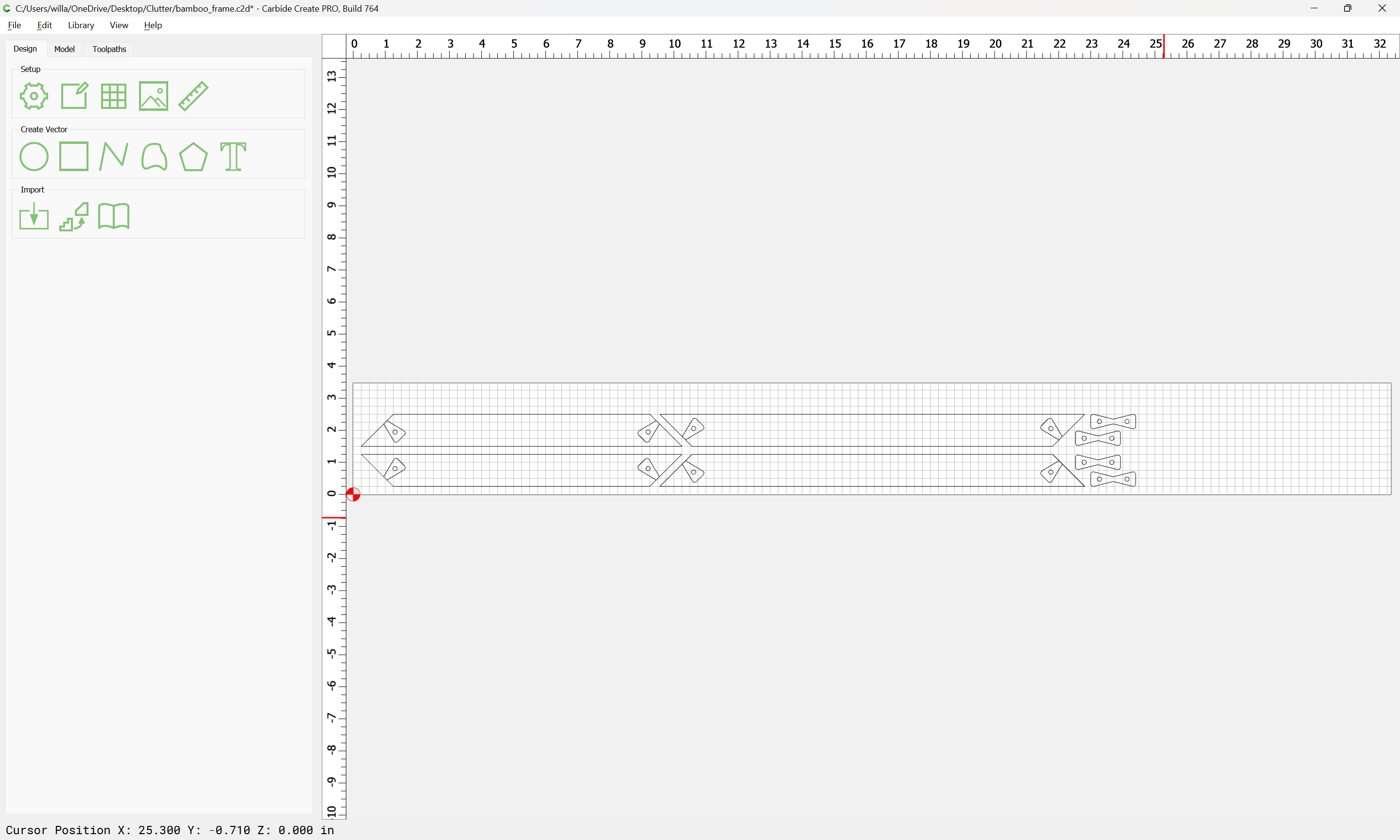
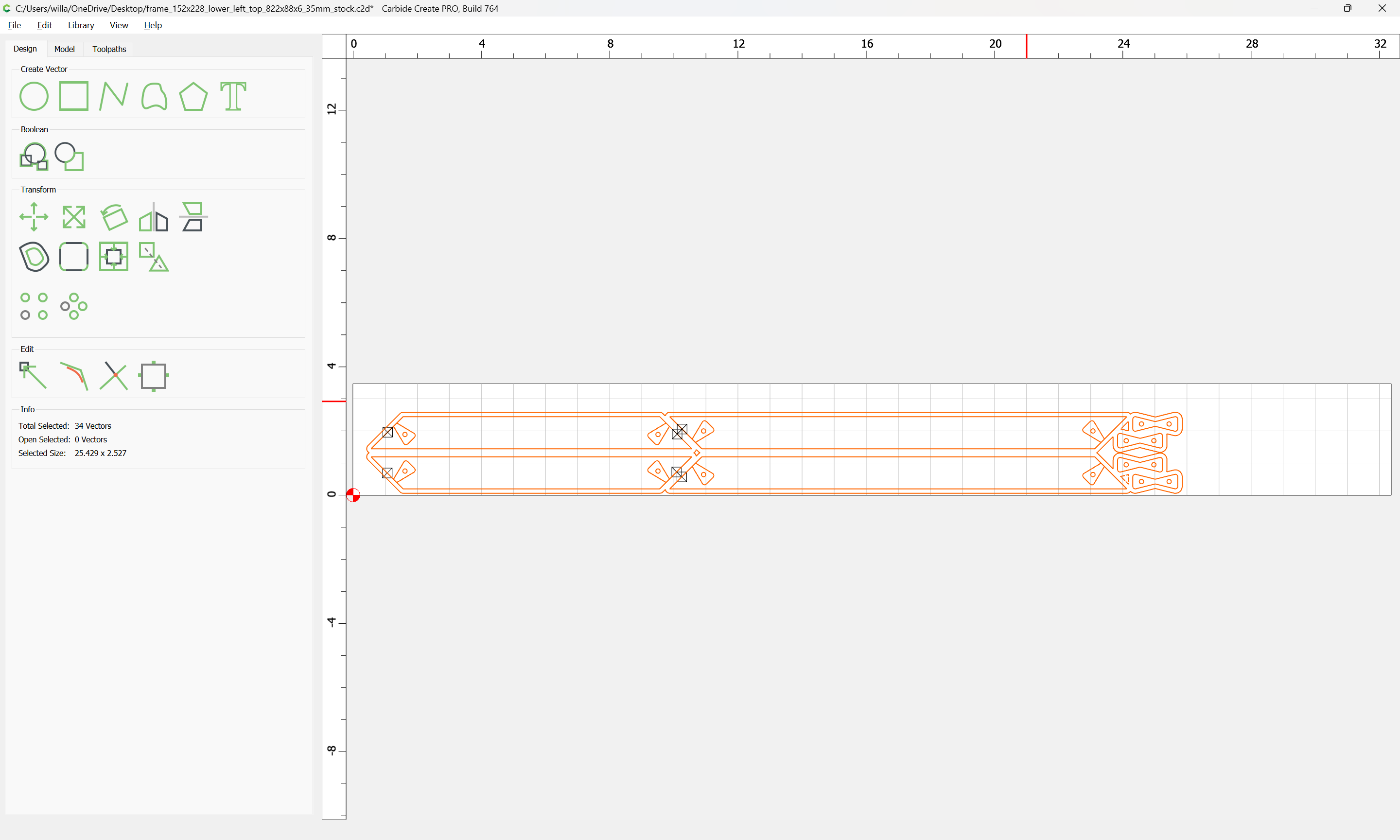
and then draw up the parts for the frame, as well as butterfly keys to secure the corners:
and position things so that they line up:
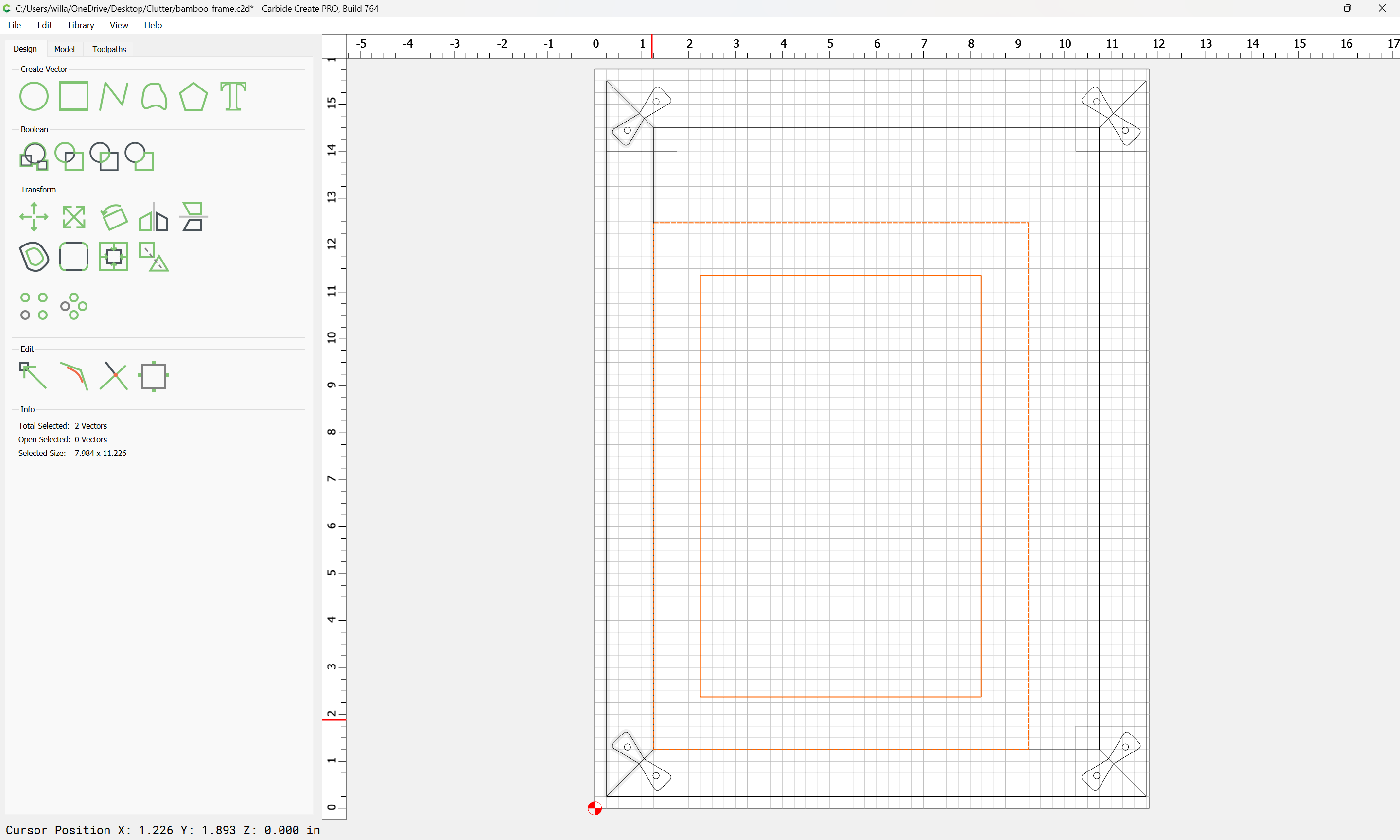
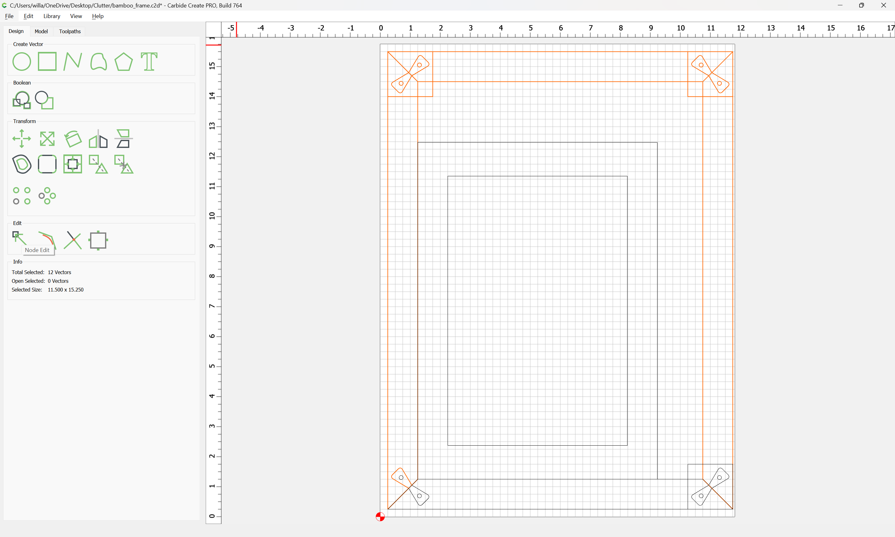
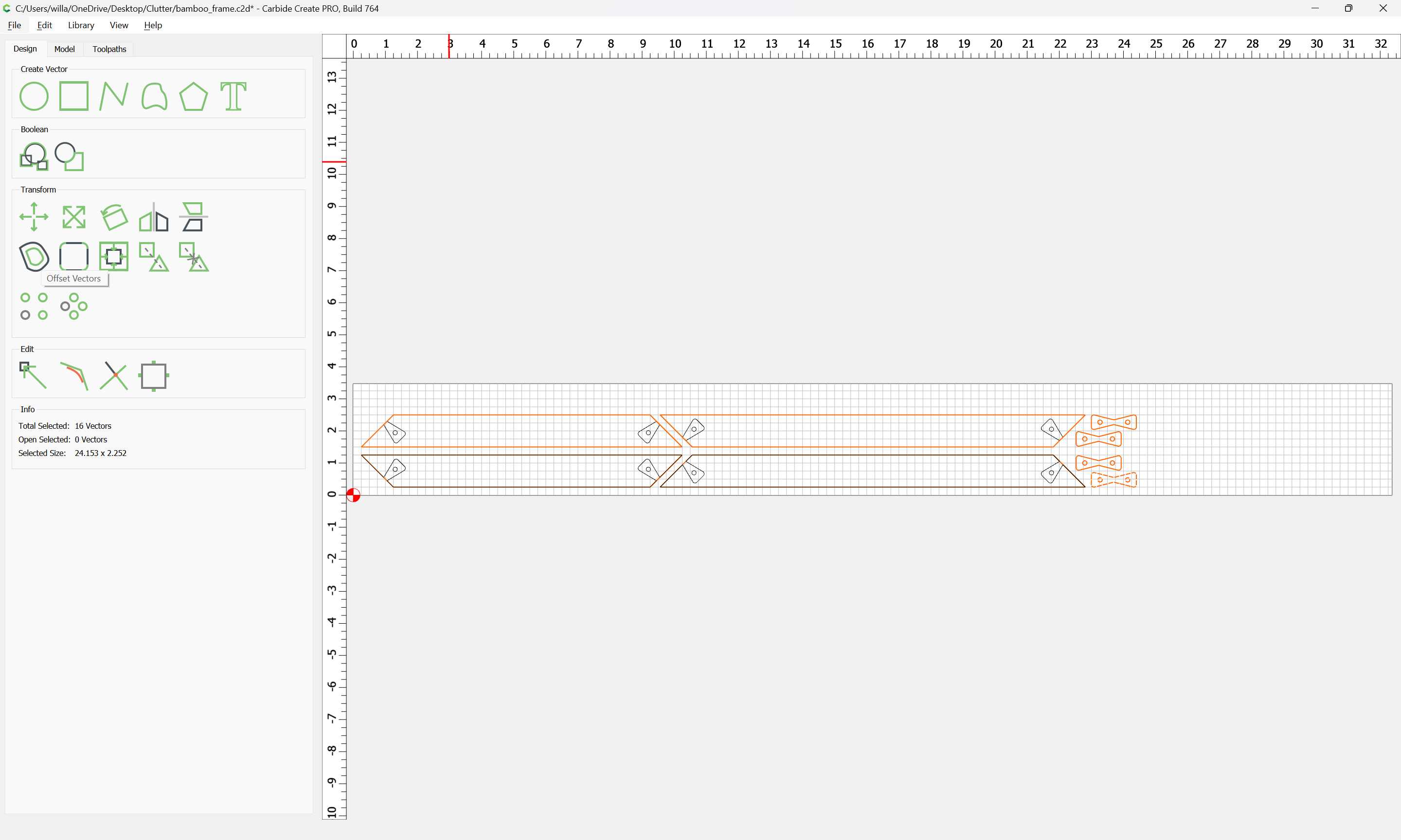
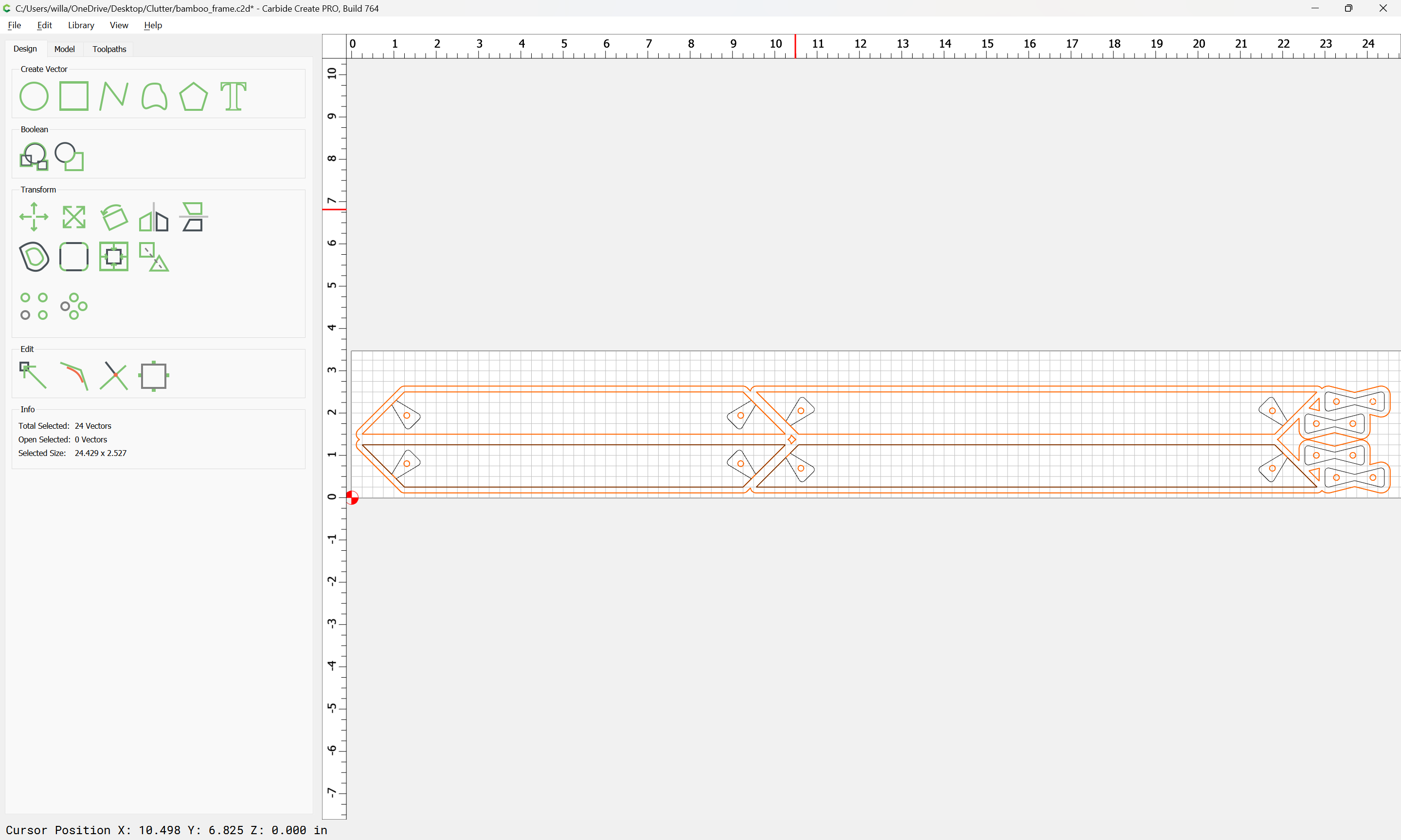
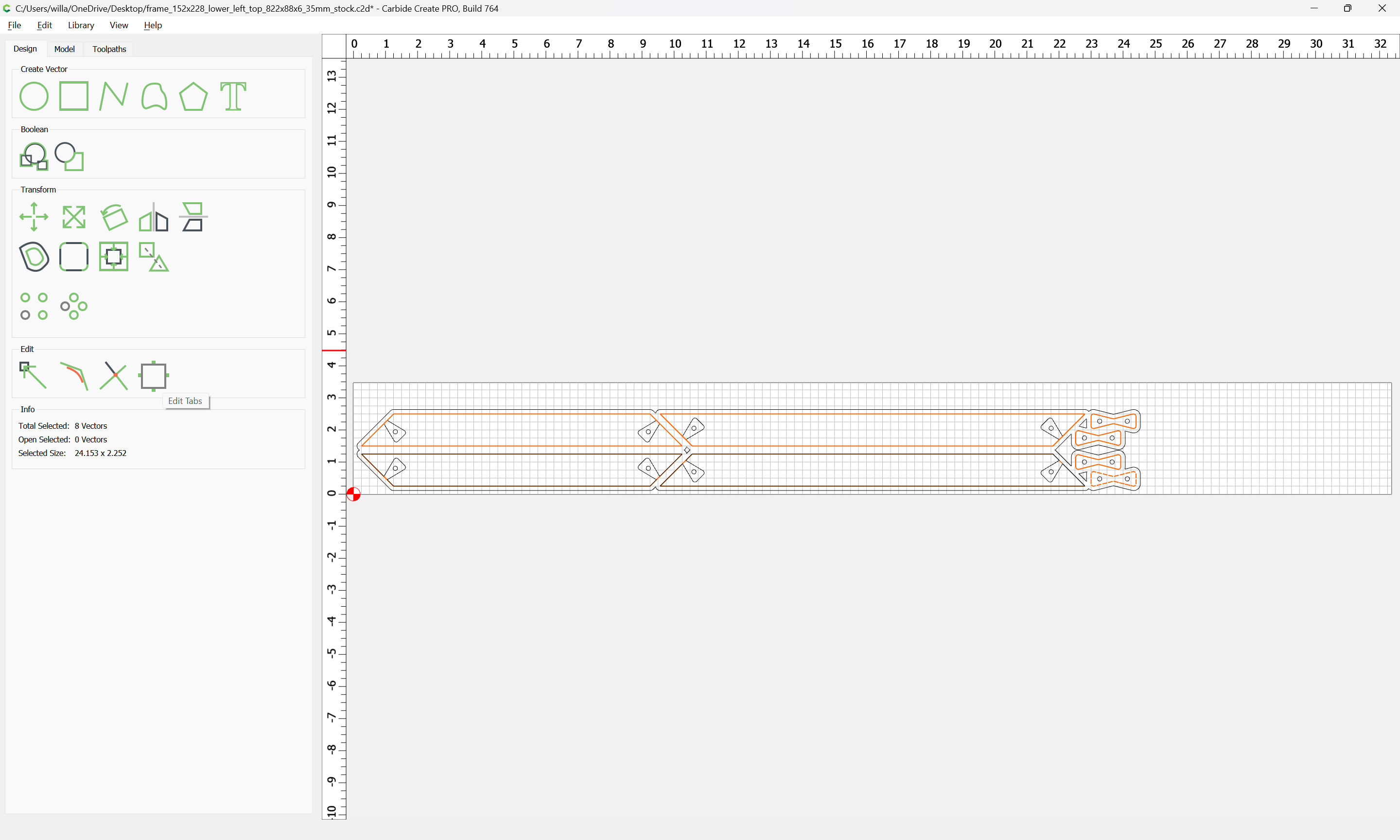
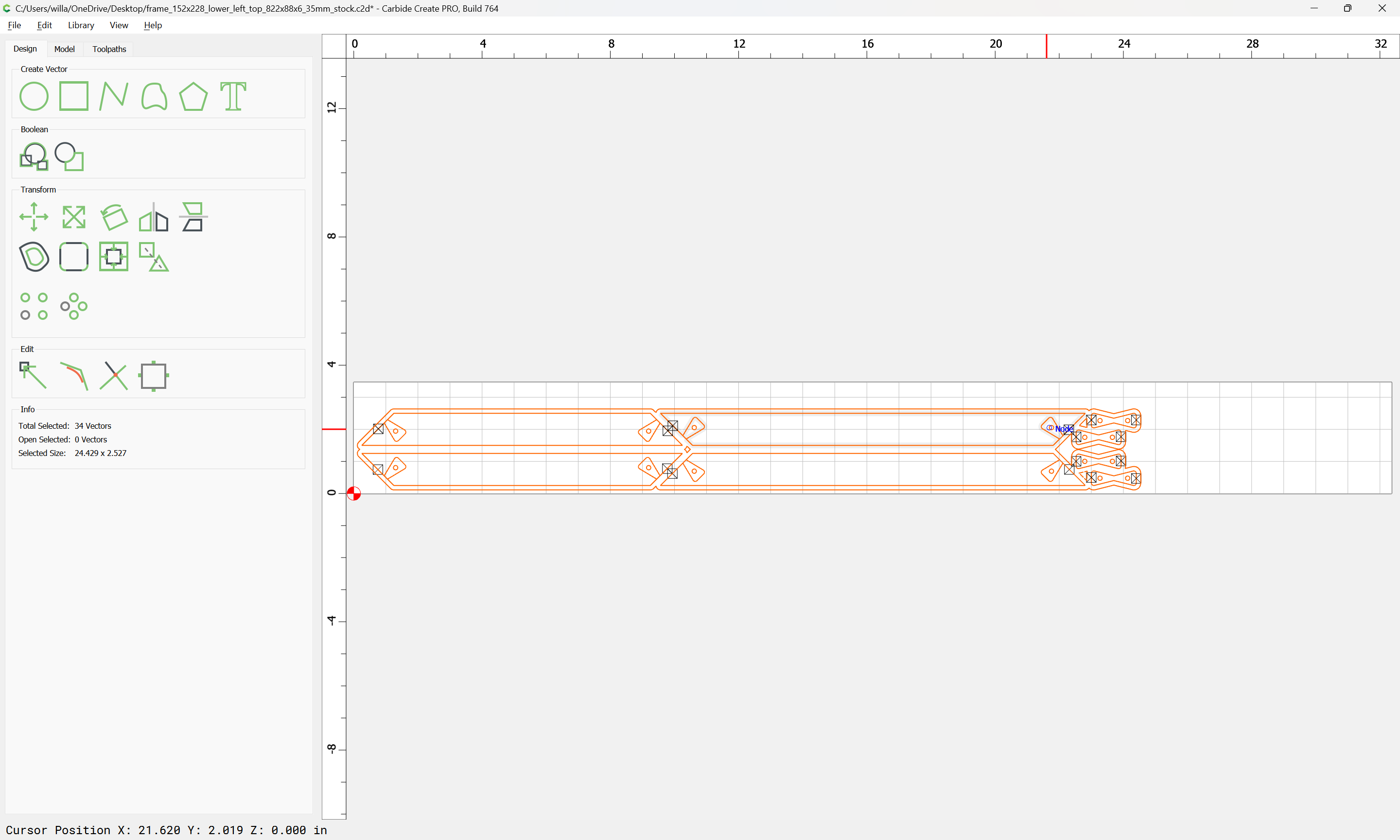
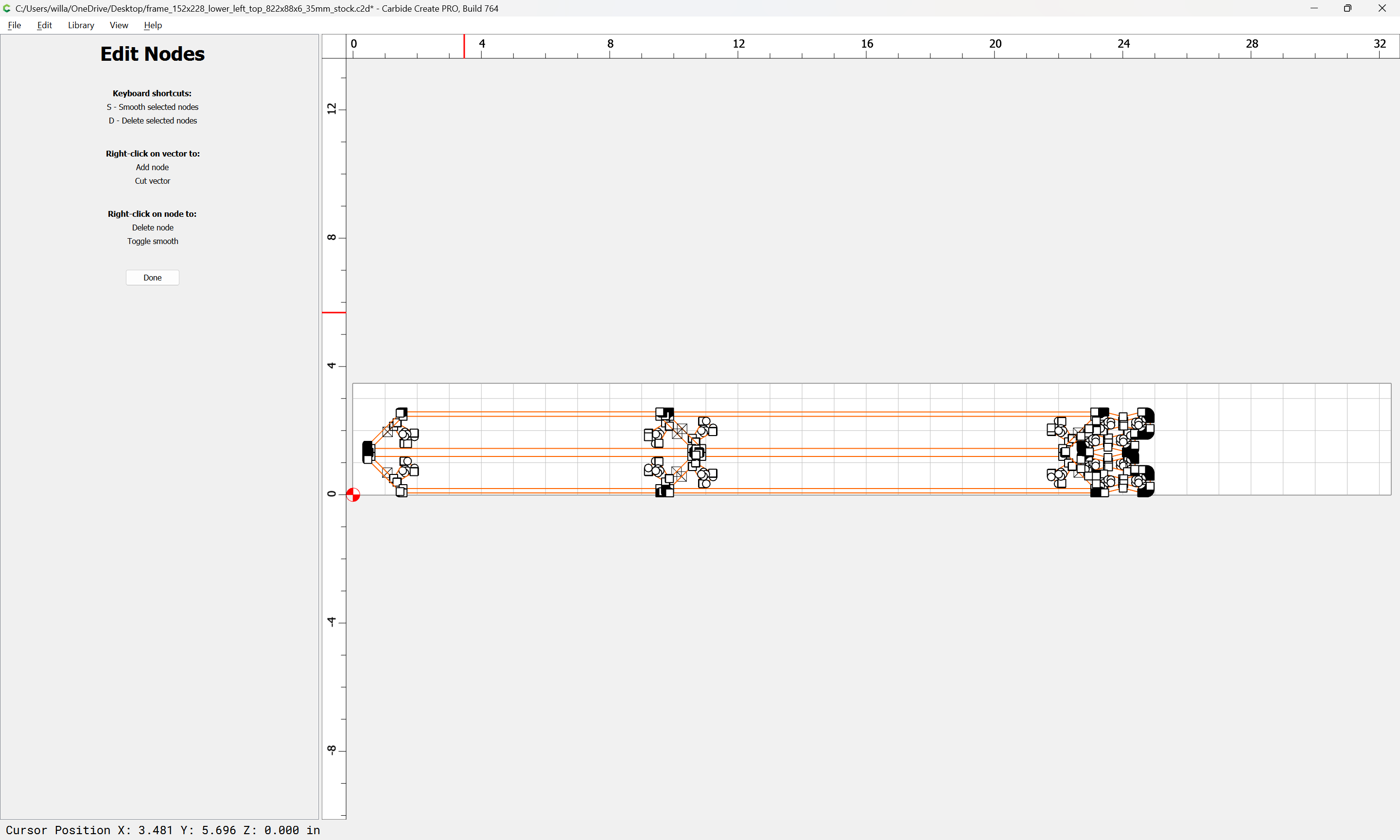
Then select things:
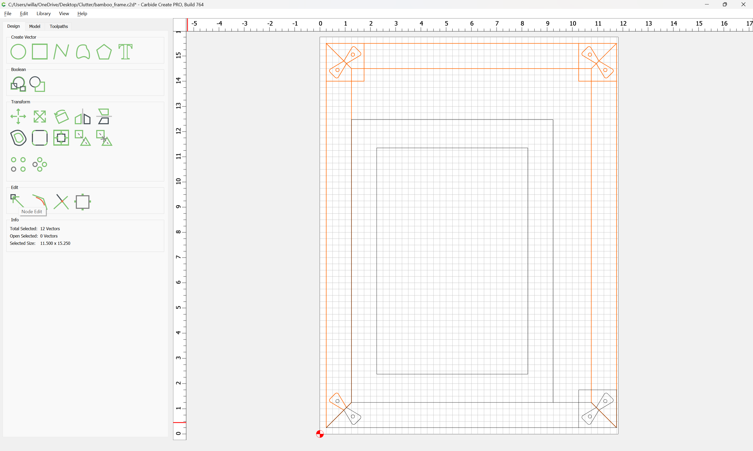
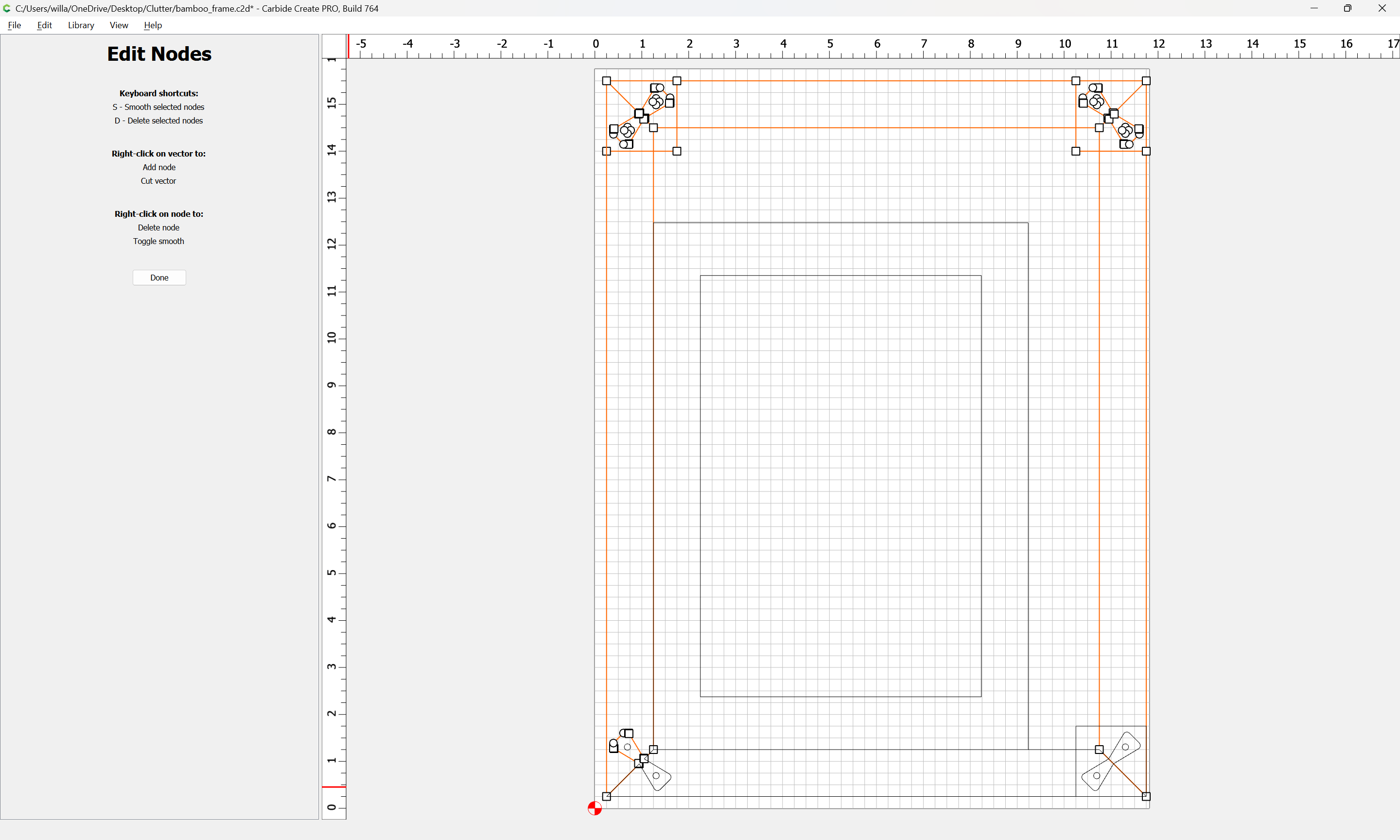
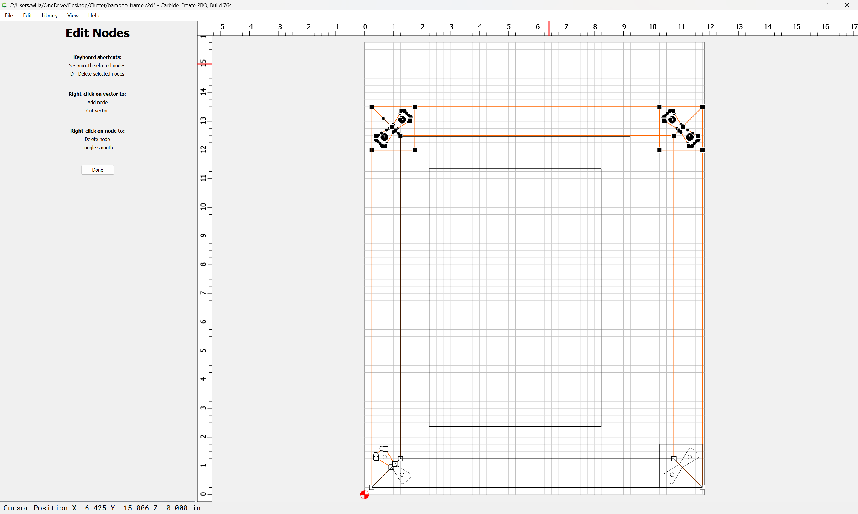
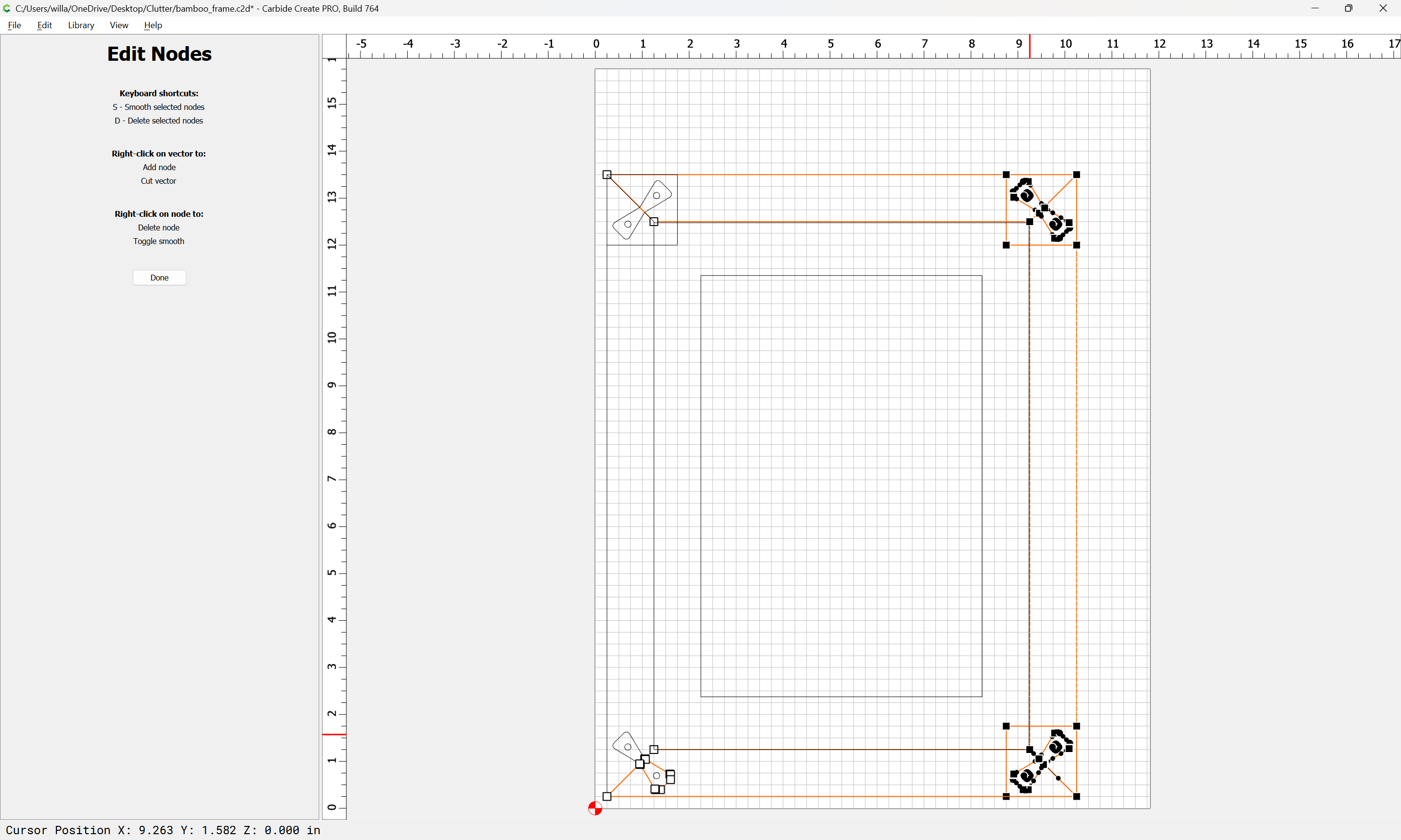
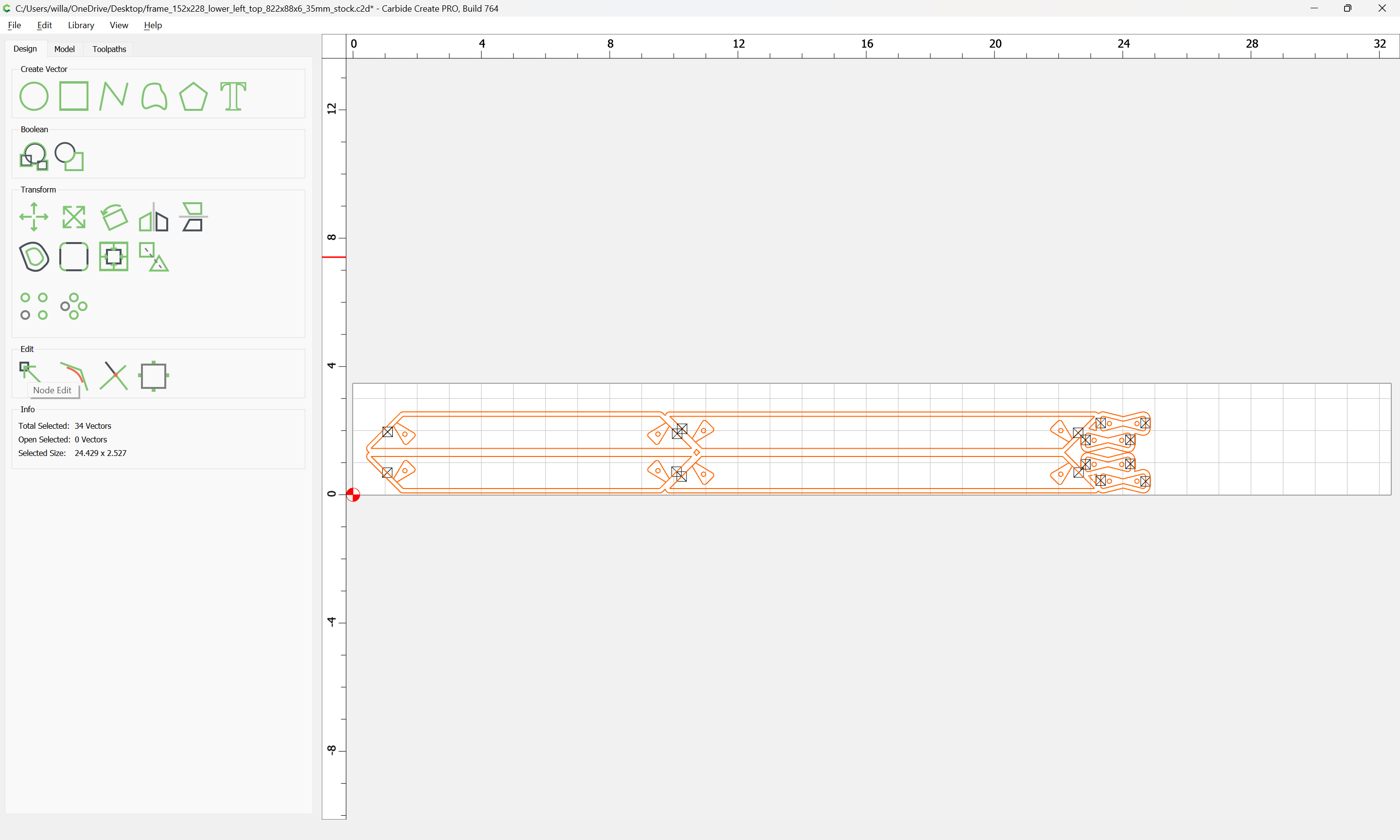
and go into Node Edit mode:
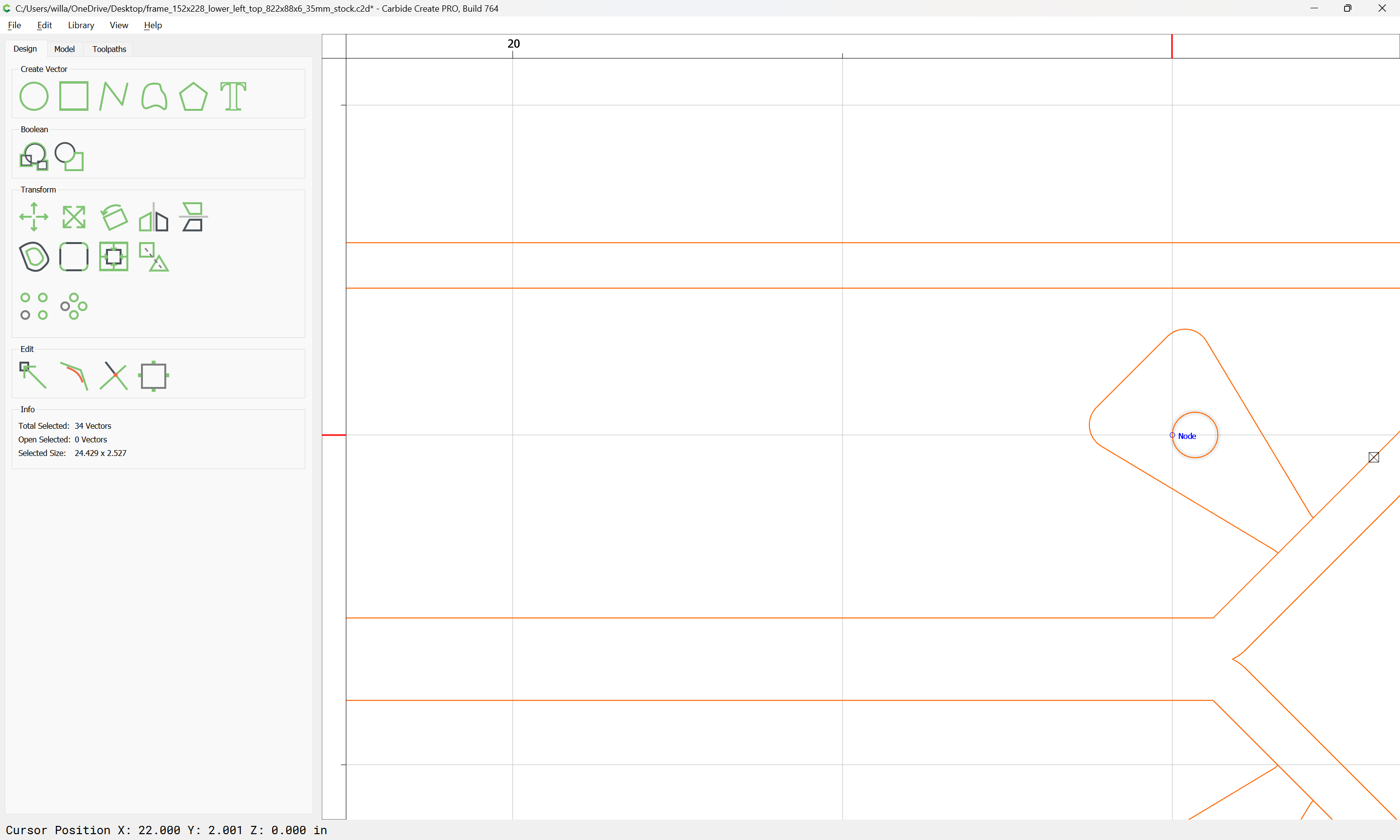
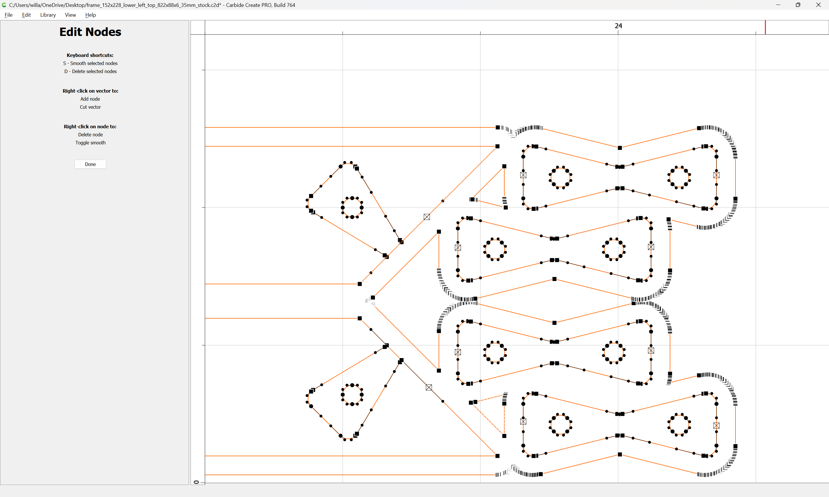
select the nodes which we wish to re-position:
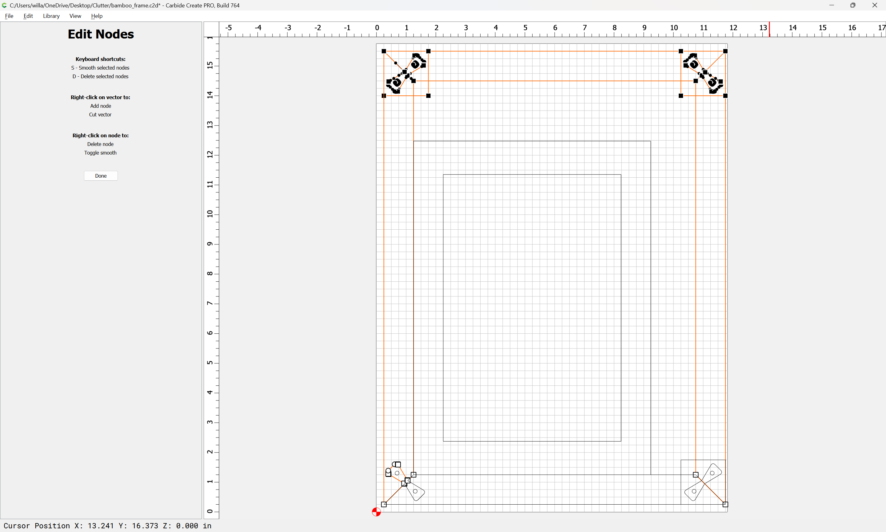
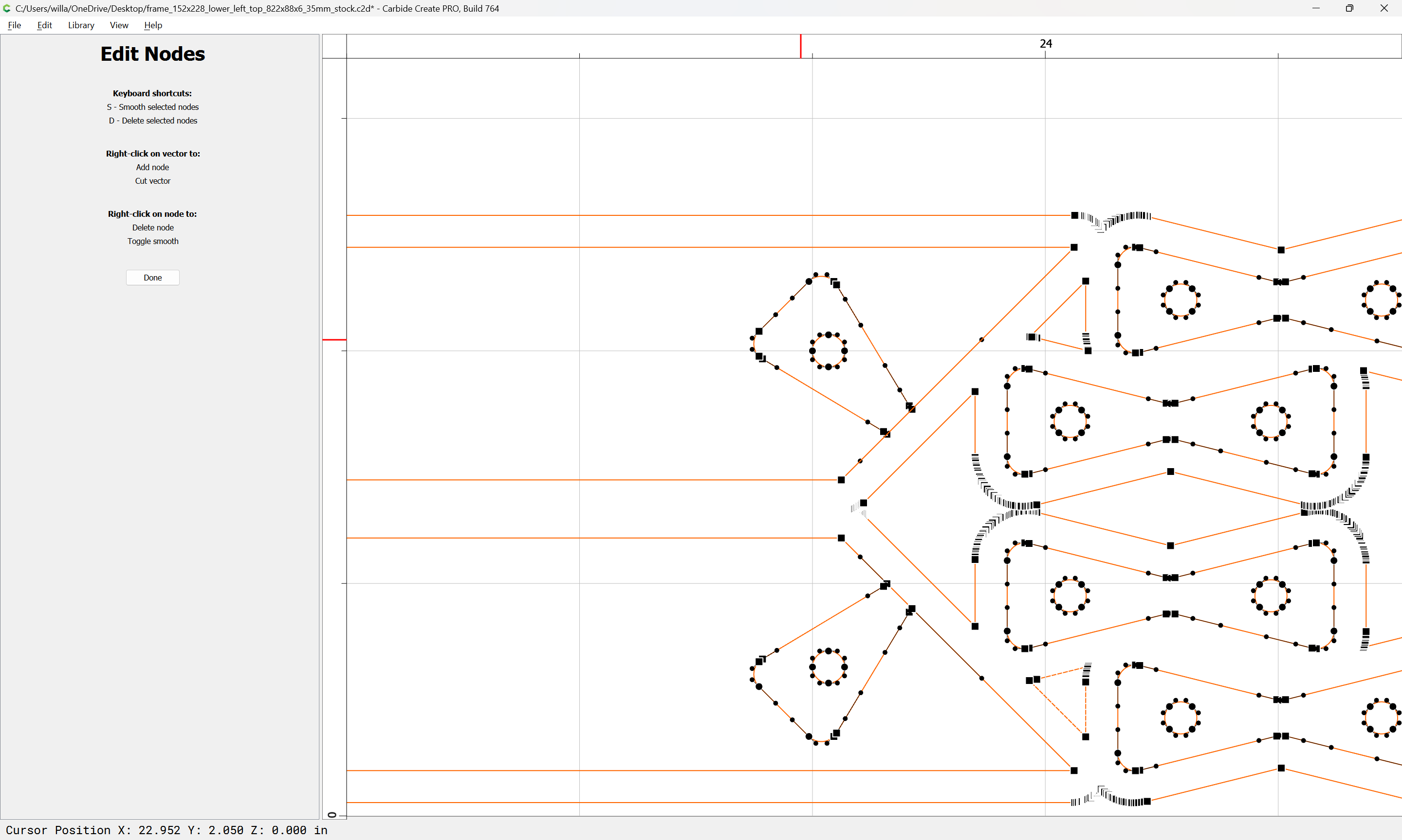
drag one which is at a grid intersection to the grid intersection we want it to be at:
and repeat:
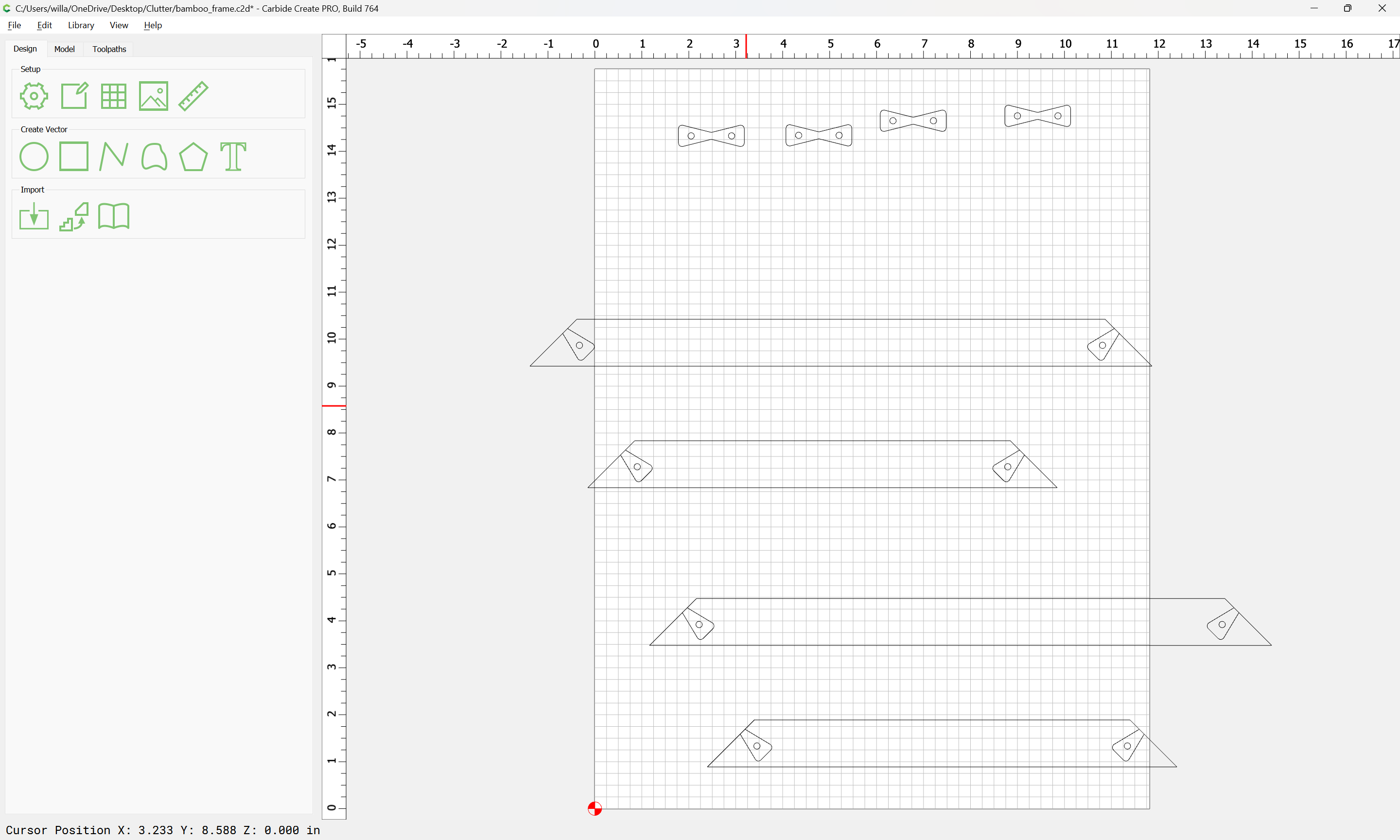
Then rotate
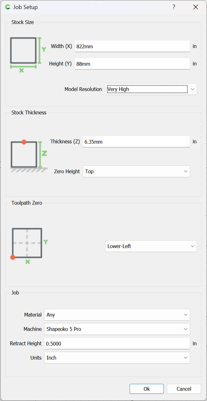
re-size the stock to match the stock which will be used:
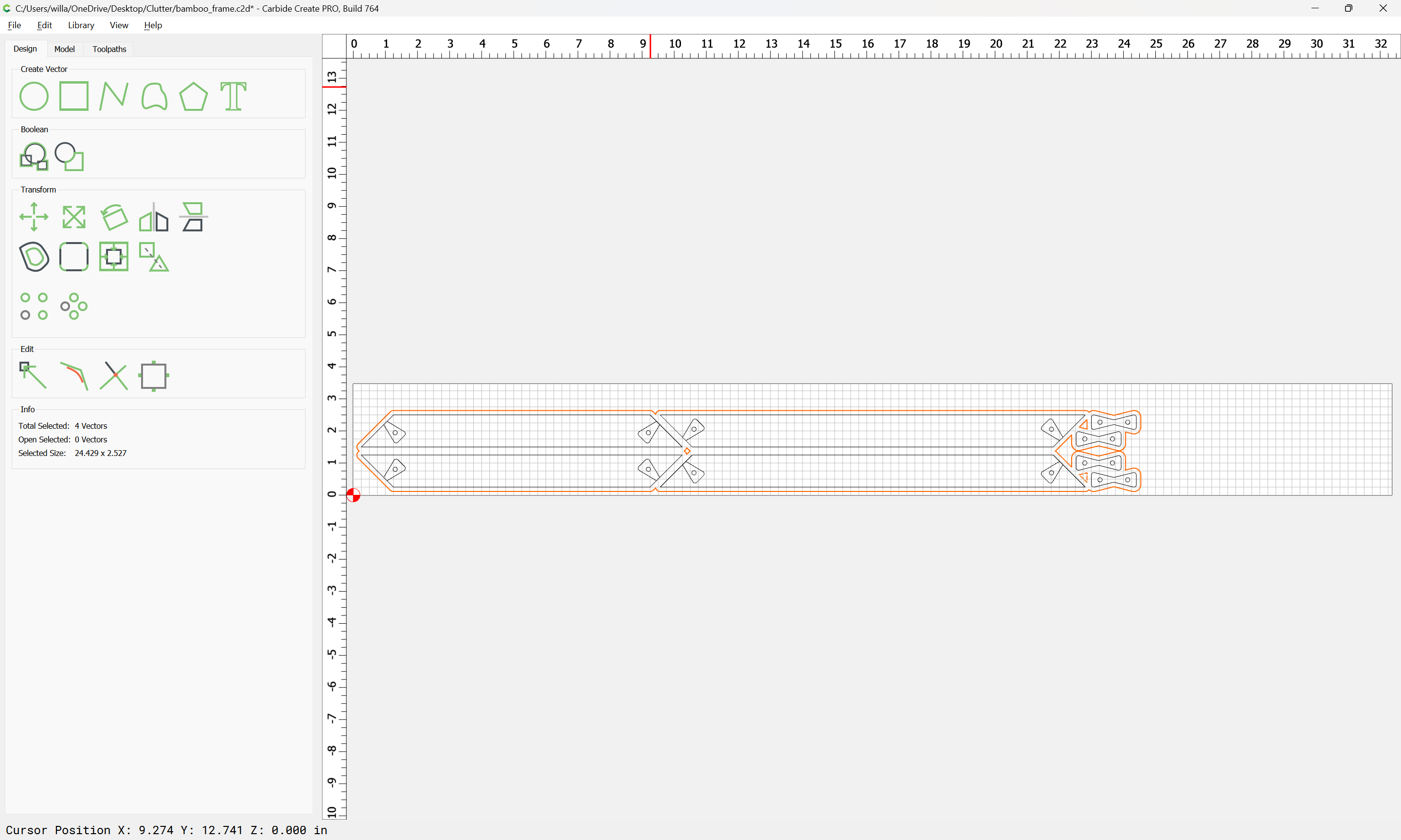
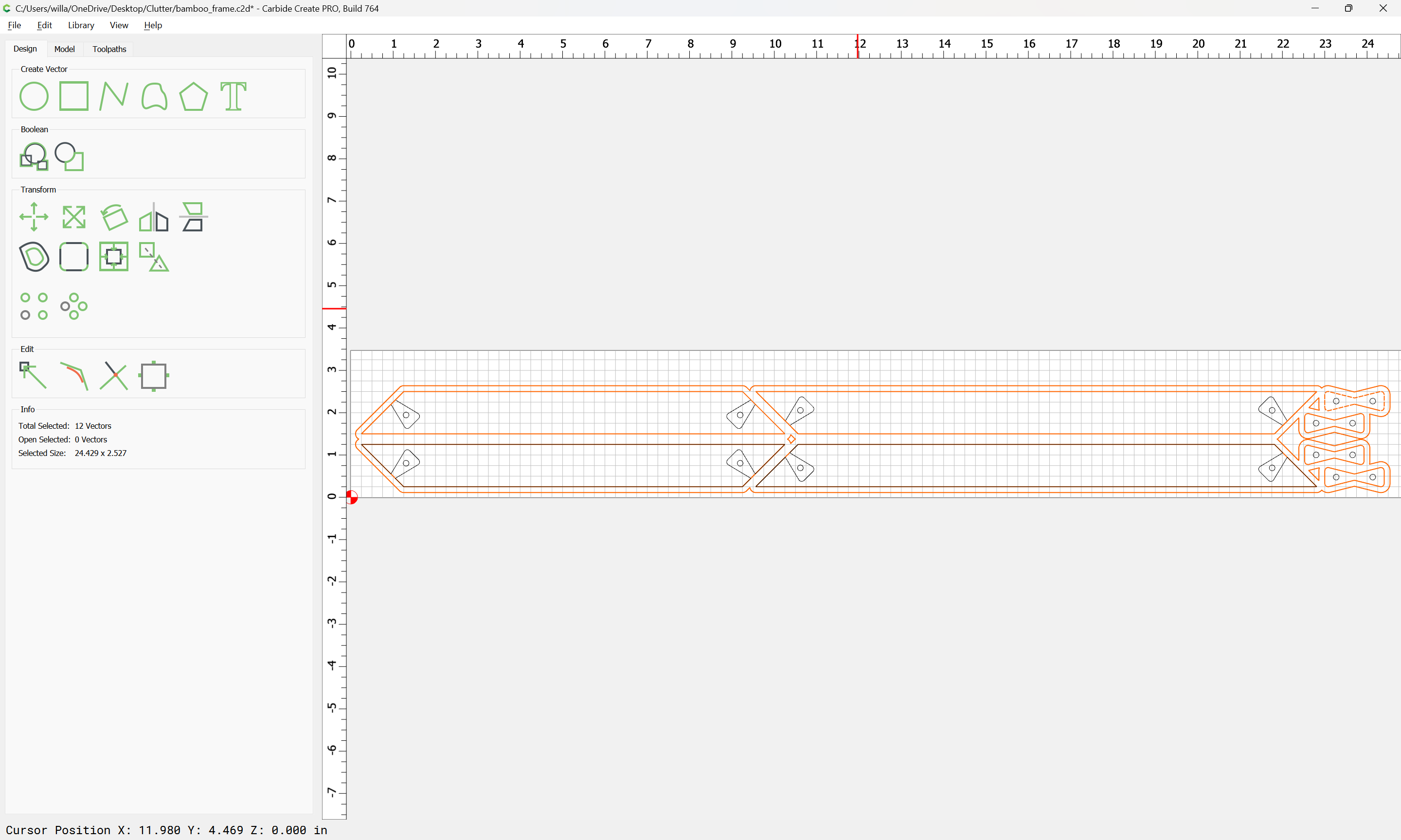
arrange the parts for efficient cutting:
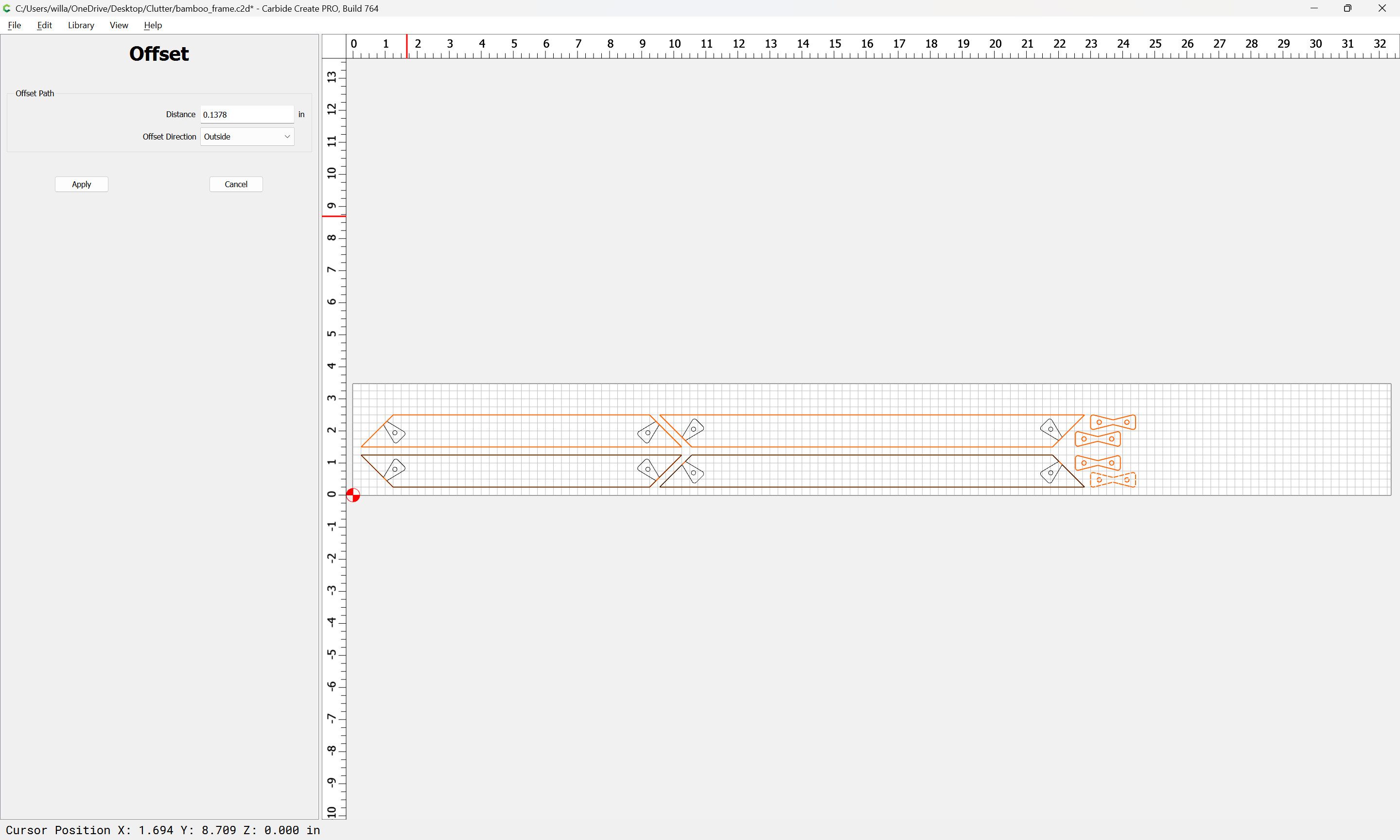
and then offset the geometry to the outside by endmill diameter plus 10%:
Apply
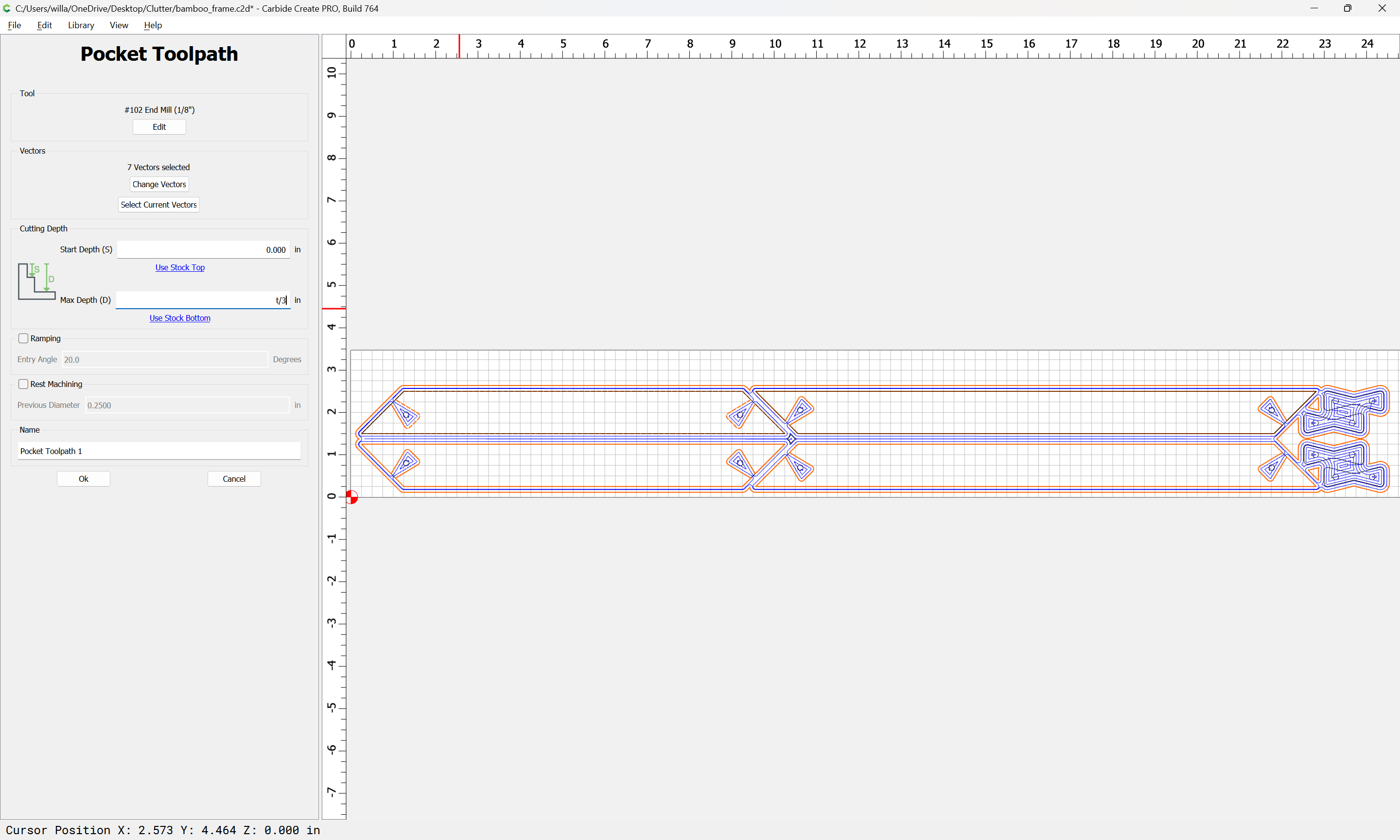
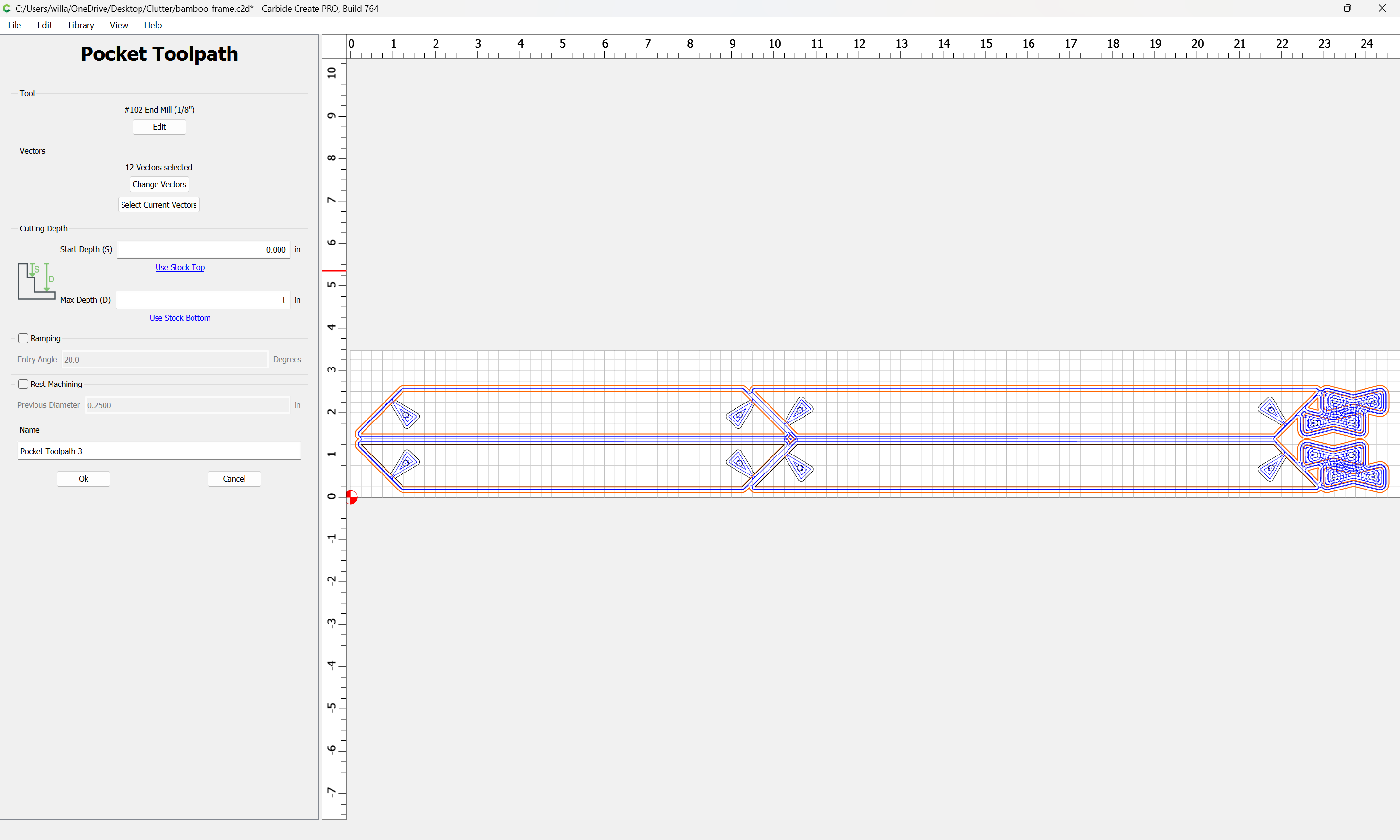
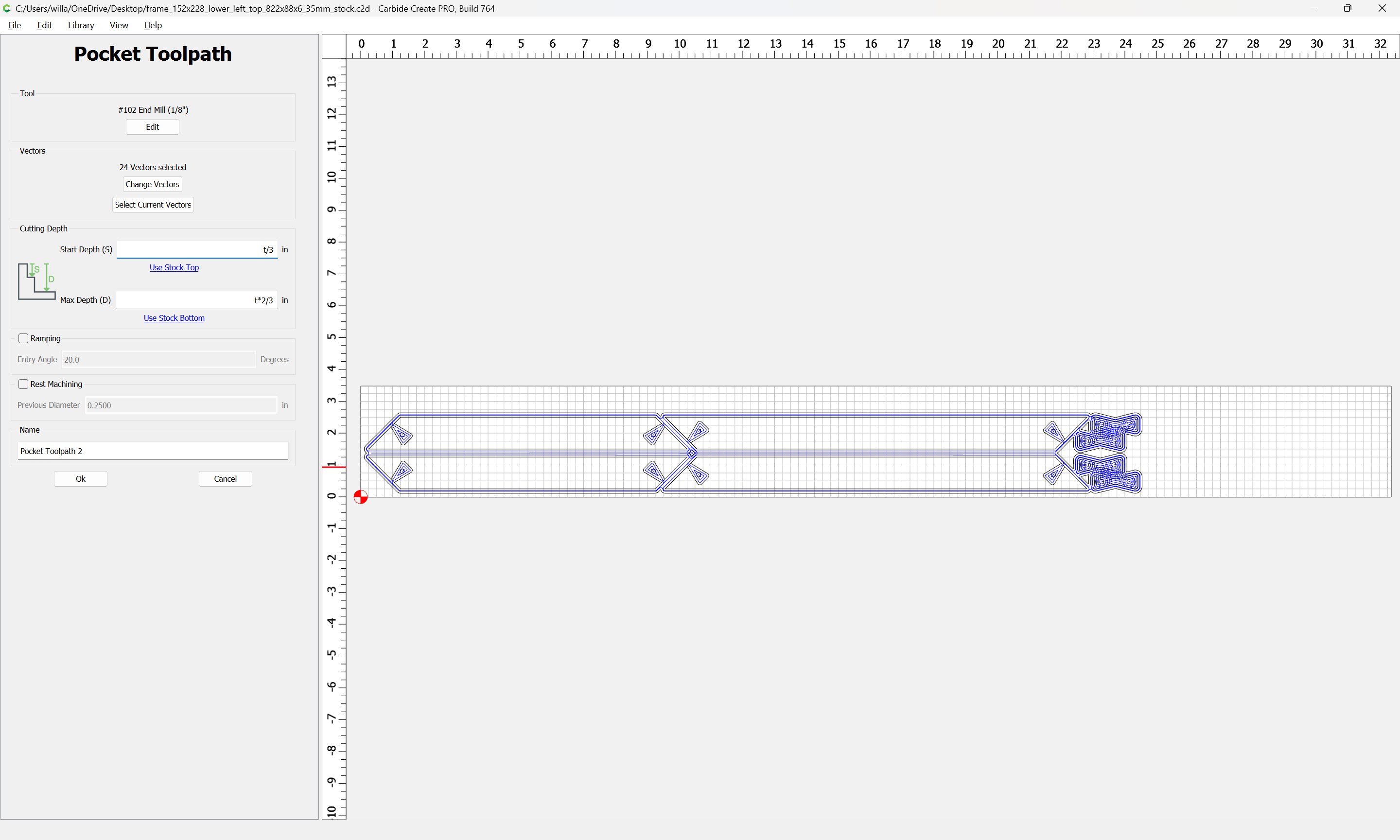
assign toolpaths — note that there will be three different levels/thicknesses:
full thickness — the frames themselves
two-thirds thickness — the pockets for the butterfly keys and the height of the buttons on the keys
one-third thickness — the uncut depth of the pockets for the buttons and the thickness of the balance of the butterfly keys
First third:
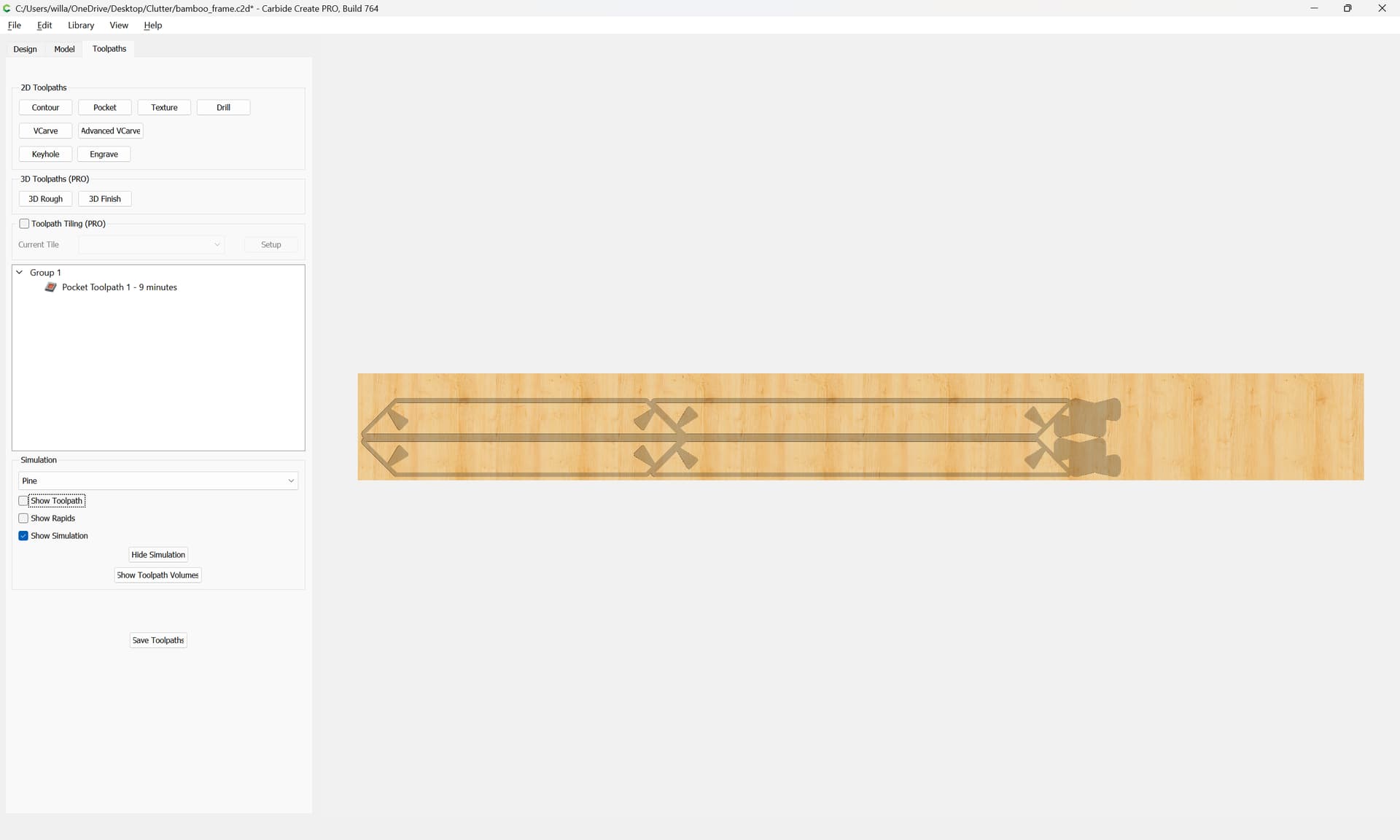
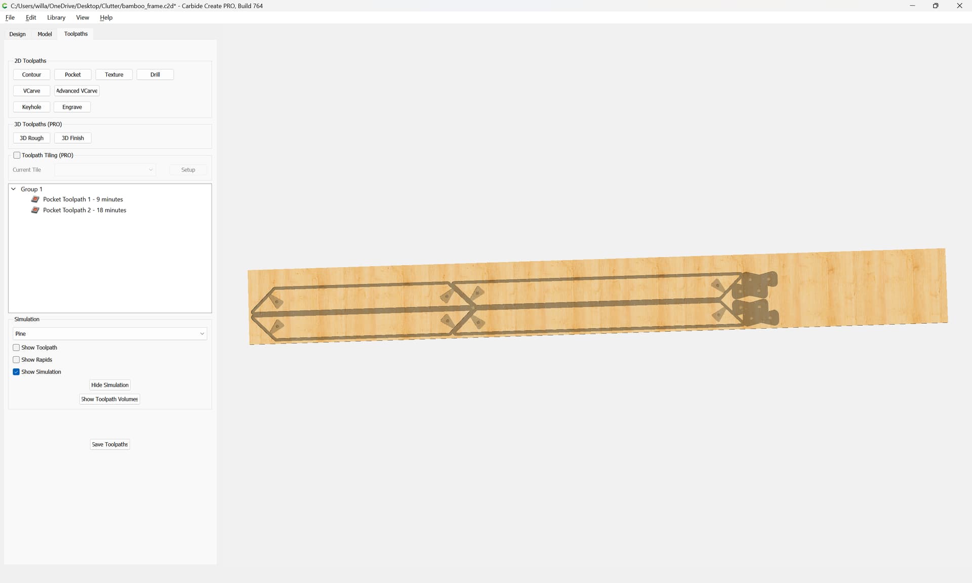
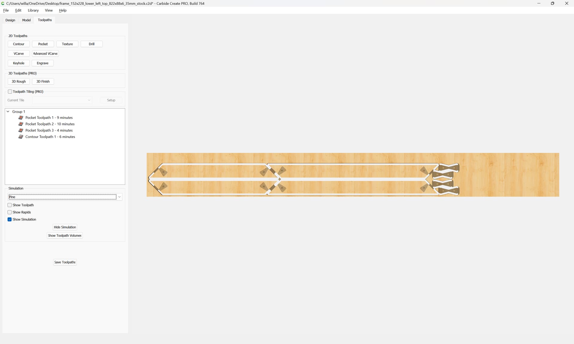
which previews as:
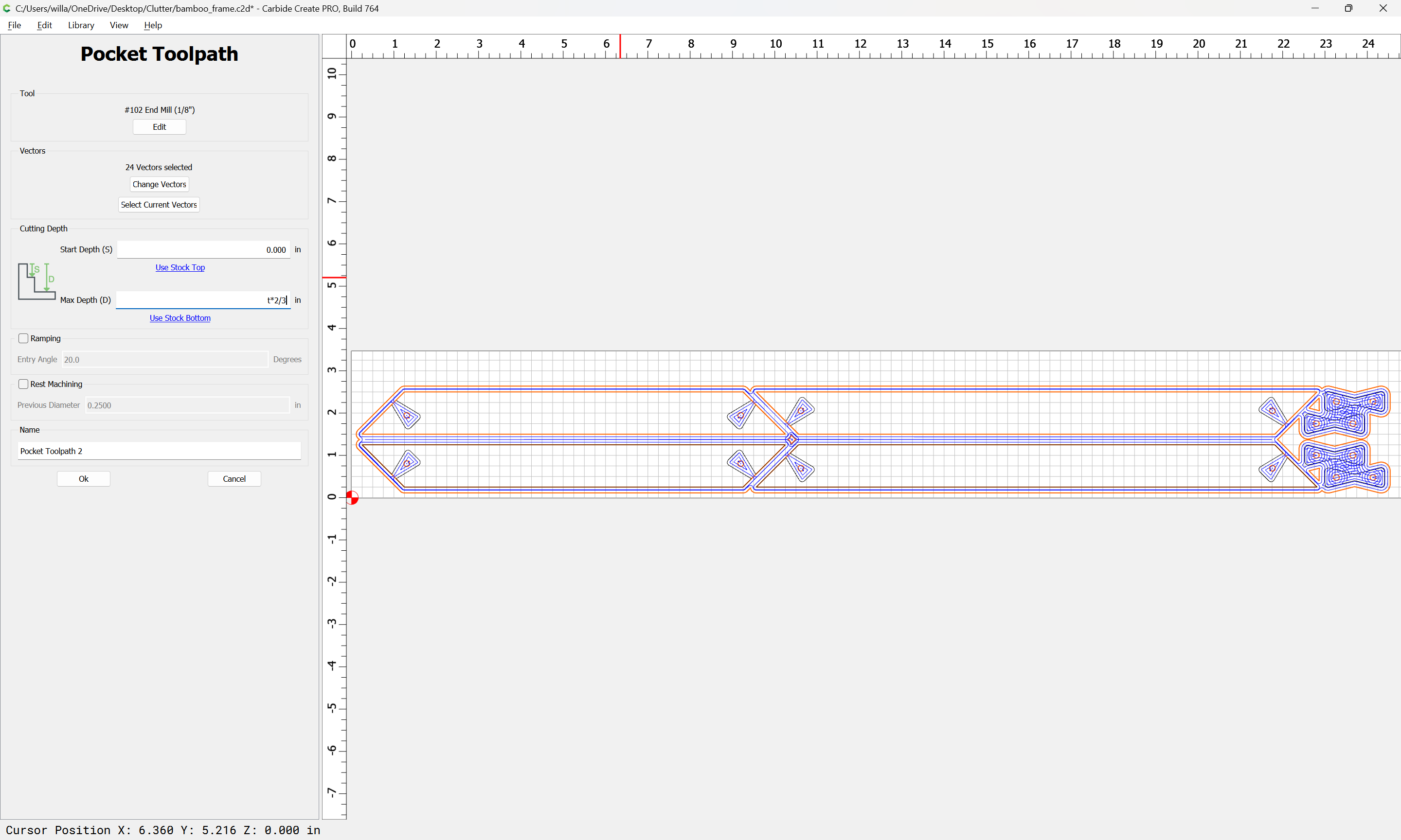
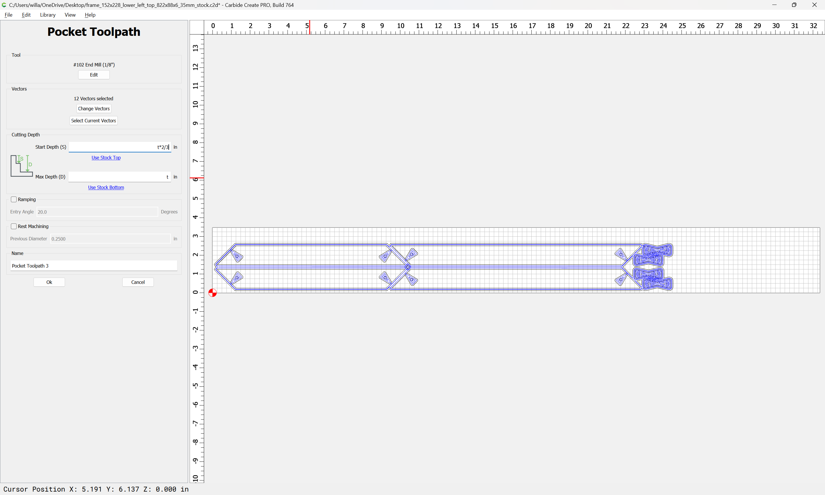
Second third:
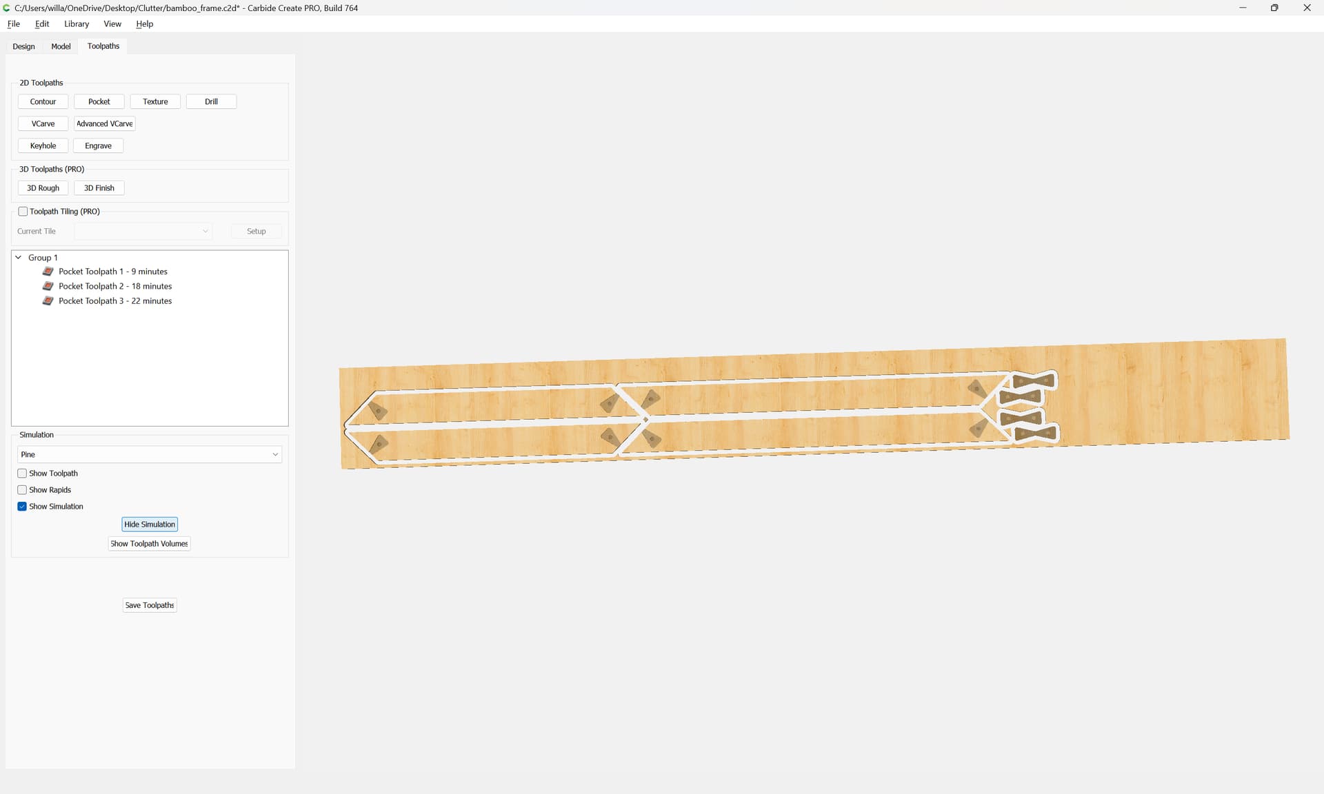
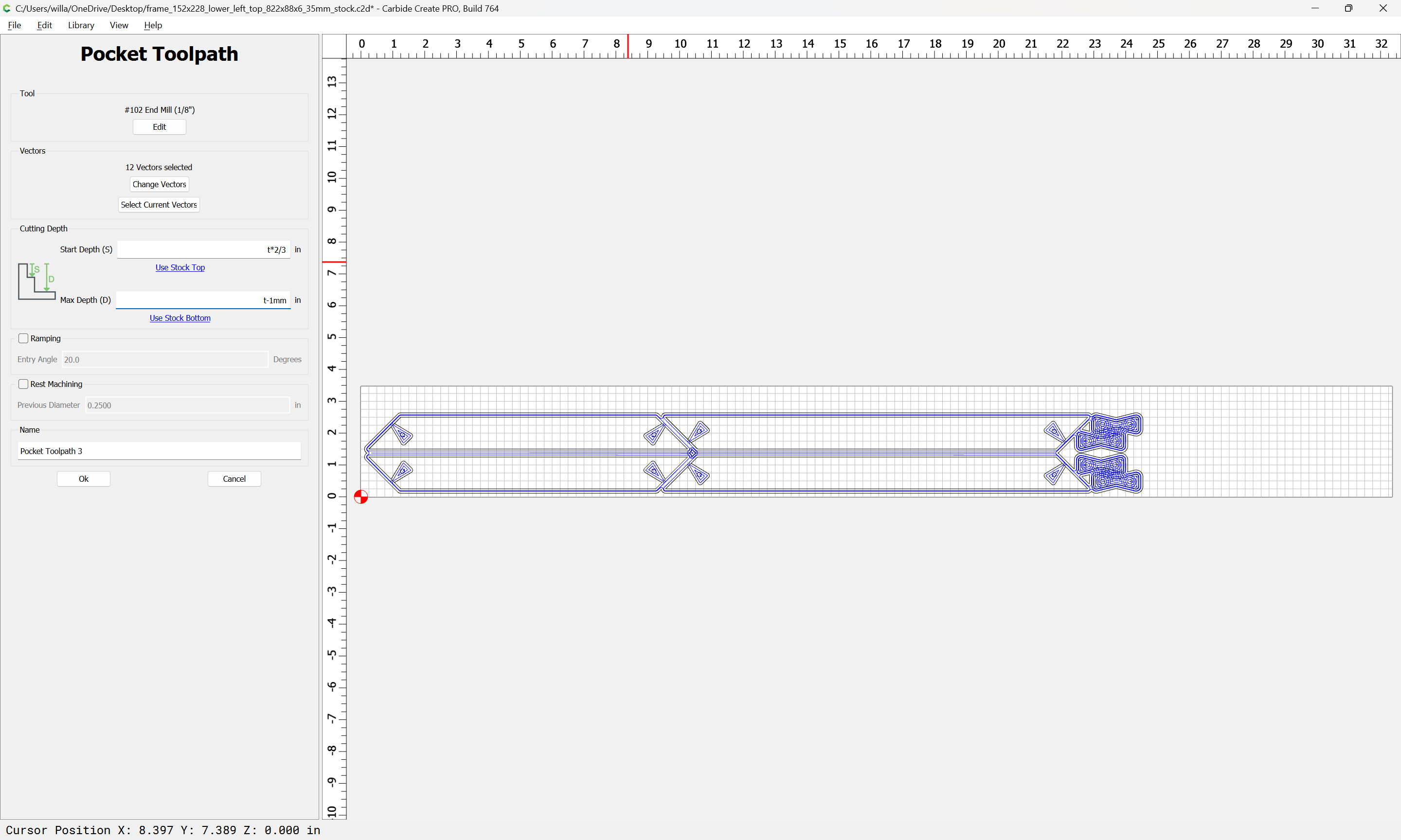
Final third:
Fixed version (see below):
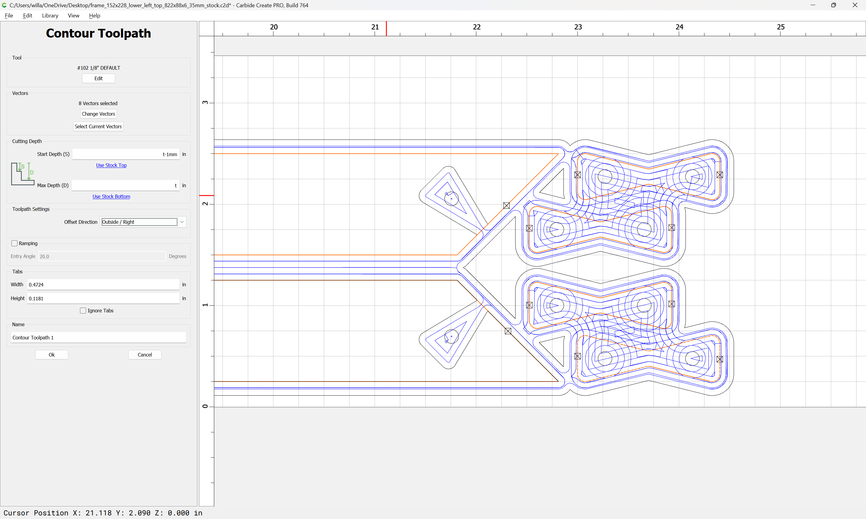
Final fix (feeds and speeds for the contour):
frame_152x228_lower_left_top_822x88x6_35mm_stock.c2d (172 KB)
1 Like
WillAdams
December 11, 2023, 2:07am
2
Two notes:
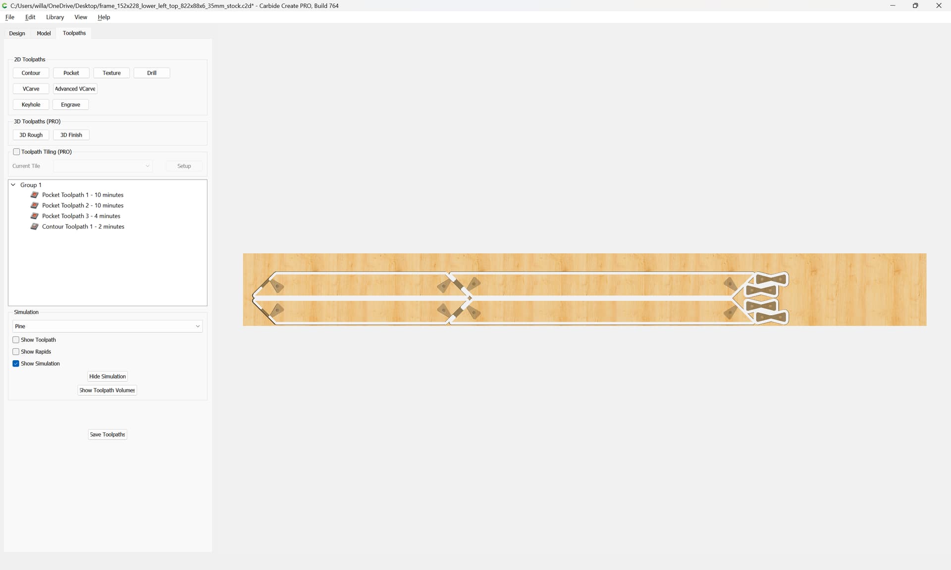
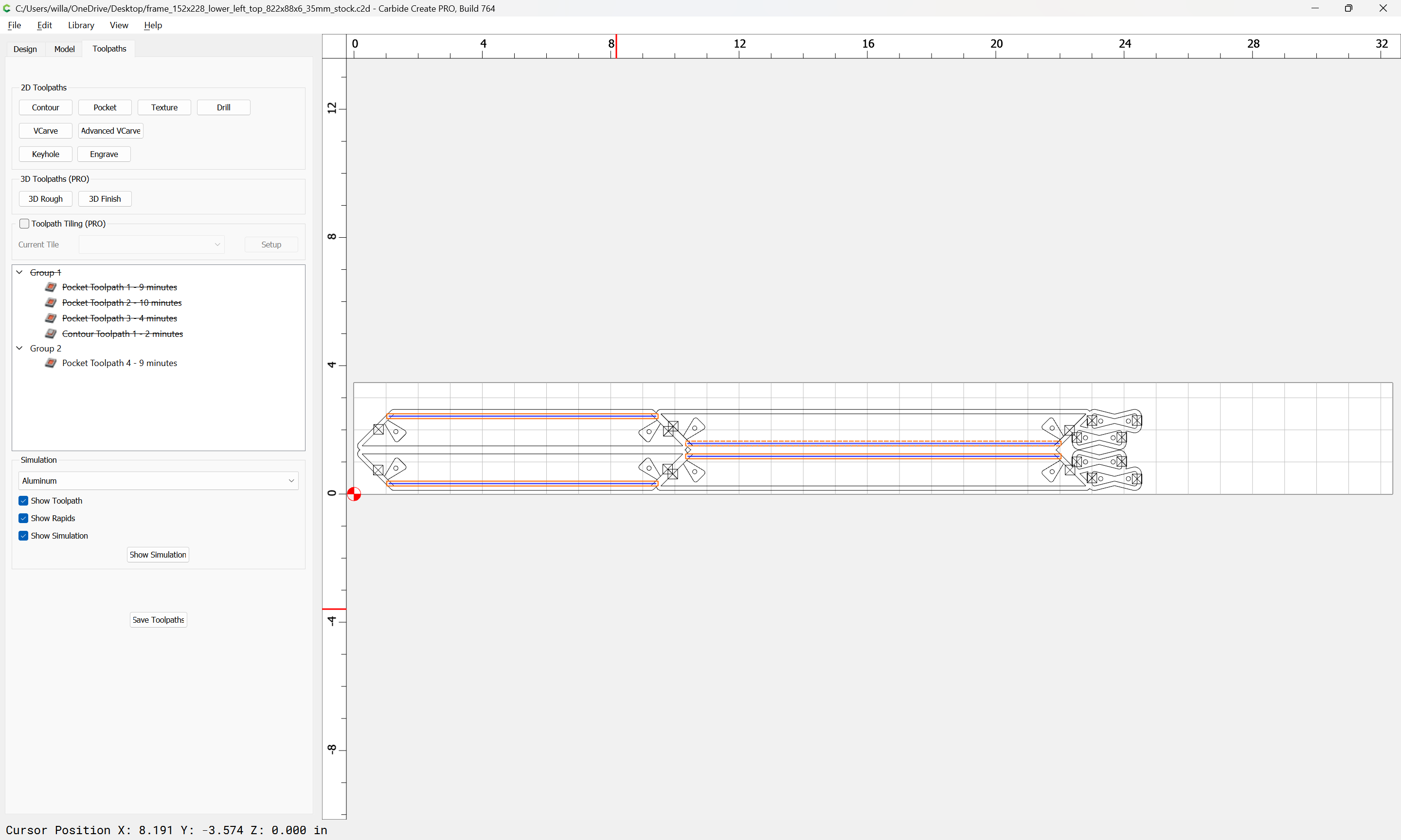
each toolpath after the first should start at the bottom of the preceding toolpath:
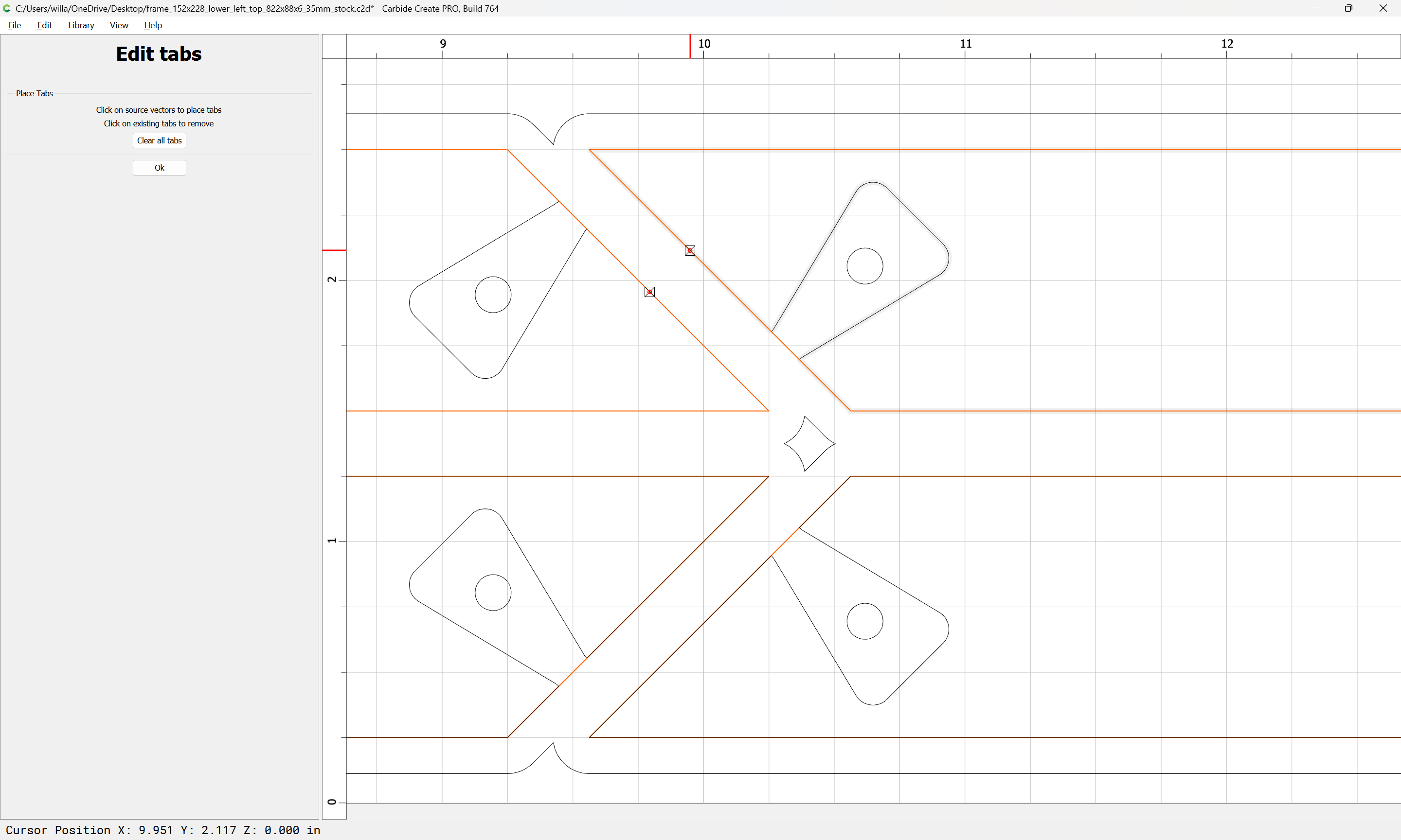
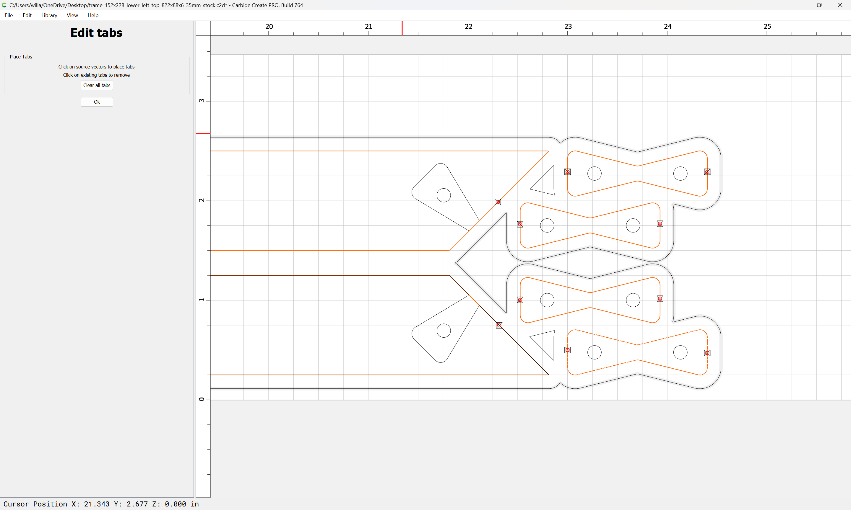
if workholding isn’t such as to secure the parts, then you will want to either leave an onionskin on the final pocket, or leave it short by tab height and add tabs:
which previews as:
Please pardon my uploading a file w/ two toolpaths disabled.
3.c2d (140 KB)
Spyd
December 11, 2023, 2:15am
3
Great tutorial! I will have to try this out. Thanks Will
WillAdams
December 11, 2023, 2:45am
4
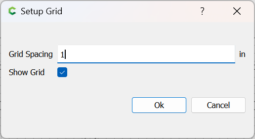
Now that the file is set up for toolpaths, it’s straight-forward to adjust for size — say one wants it to be 1" taller — set the grid increment to 1":
Select everything:
Move a node to a grid increment:
Go into Node Edit mode:
Select all the nodes which should be moved:
Move over 1 grid unit:
Done
1 Like
WillAdams
December 17, 2023, 10:55pm
5
One oversight here is that no rabbet was made for the glass.
frame_152x228_lower_left_top_822x88x6_35mm_stock.c2d (132 KB)
SDGuy
December 18, 2023, 1:53am
6
Thank you for posting this.
I love the indexing pins on the Butterfly Keys—great Idea and perfectly executed.
WillAdams
December 18, 2023, 1:55am
7
Note that perfect — I’m pretty sure either the pockets need to be larger, or the pins a bit smaller.
SDGuy
December 18, 2023, 1:56am
8
Nothing 15-ton press can’t fix…lol…
1 Like
I don’t know if CC has this, but it sure would be handy for these type of fits.
Vectric software has an allowance function in toolpaths. I standardized my pathing on these type of cuts to draw the inny and the outty with the same size profile (knowing that it won’t fit that way.) Then I use the allowance function to get the fit that I want. The advantage is that you don’t have to redraw anything; just recalculate the toolpath with the new adjustment.
1 Like
system
January 17, 2024, 11:48am
10
This topic was automatically closed 30 days after the last reply. New replies are no longer allowed.