Making a wrist rest from an STL using two-sided machining

As requested on support…

Given a stock size of:

15" x 4" with stock thickness of .75"

and an STL:

which arguably requires two-sided machining:

We create such a file in Carbide Create:

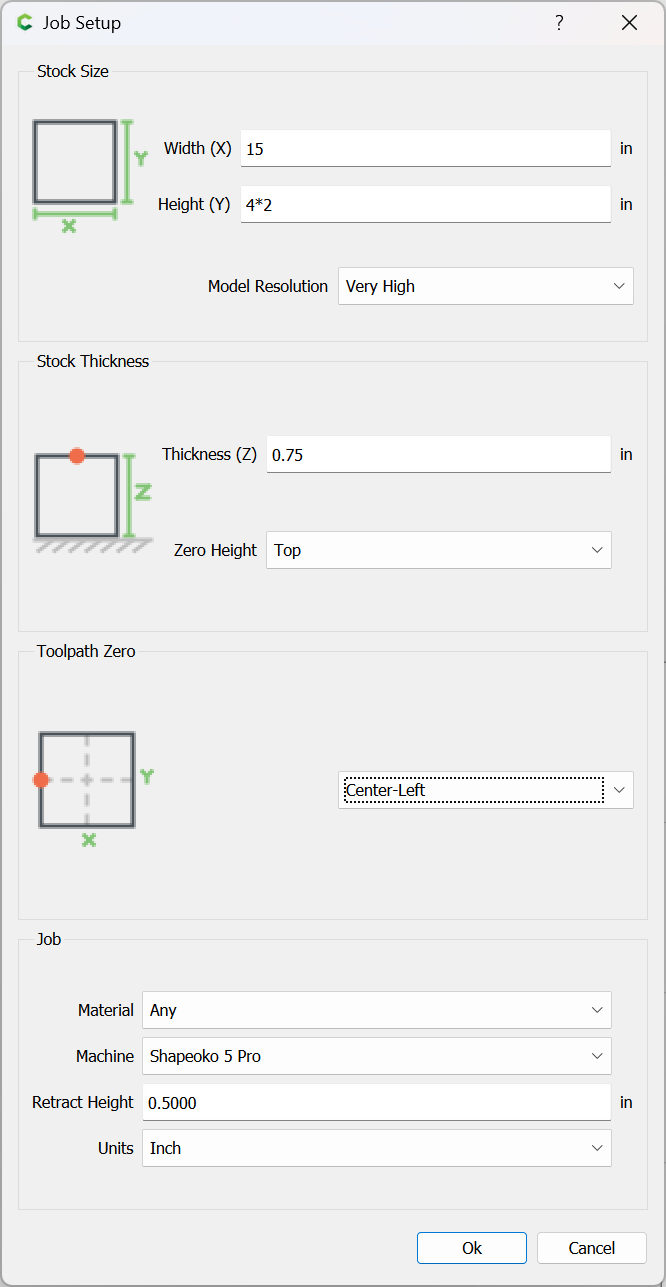
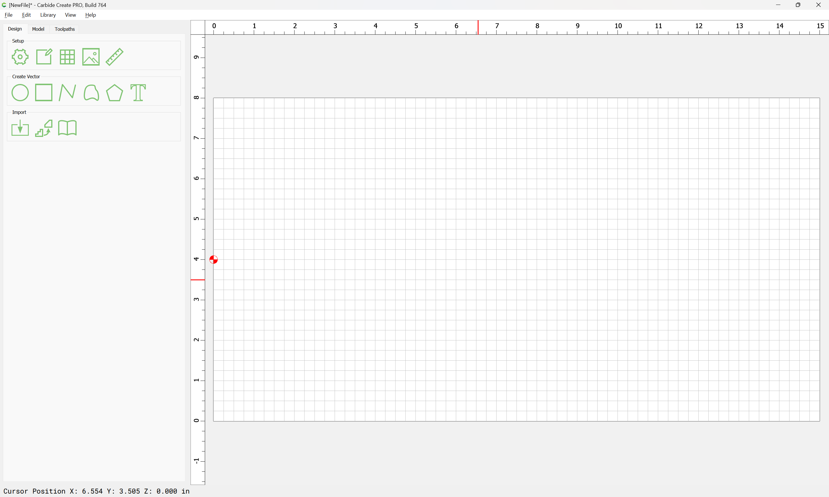
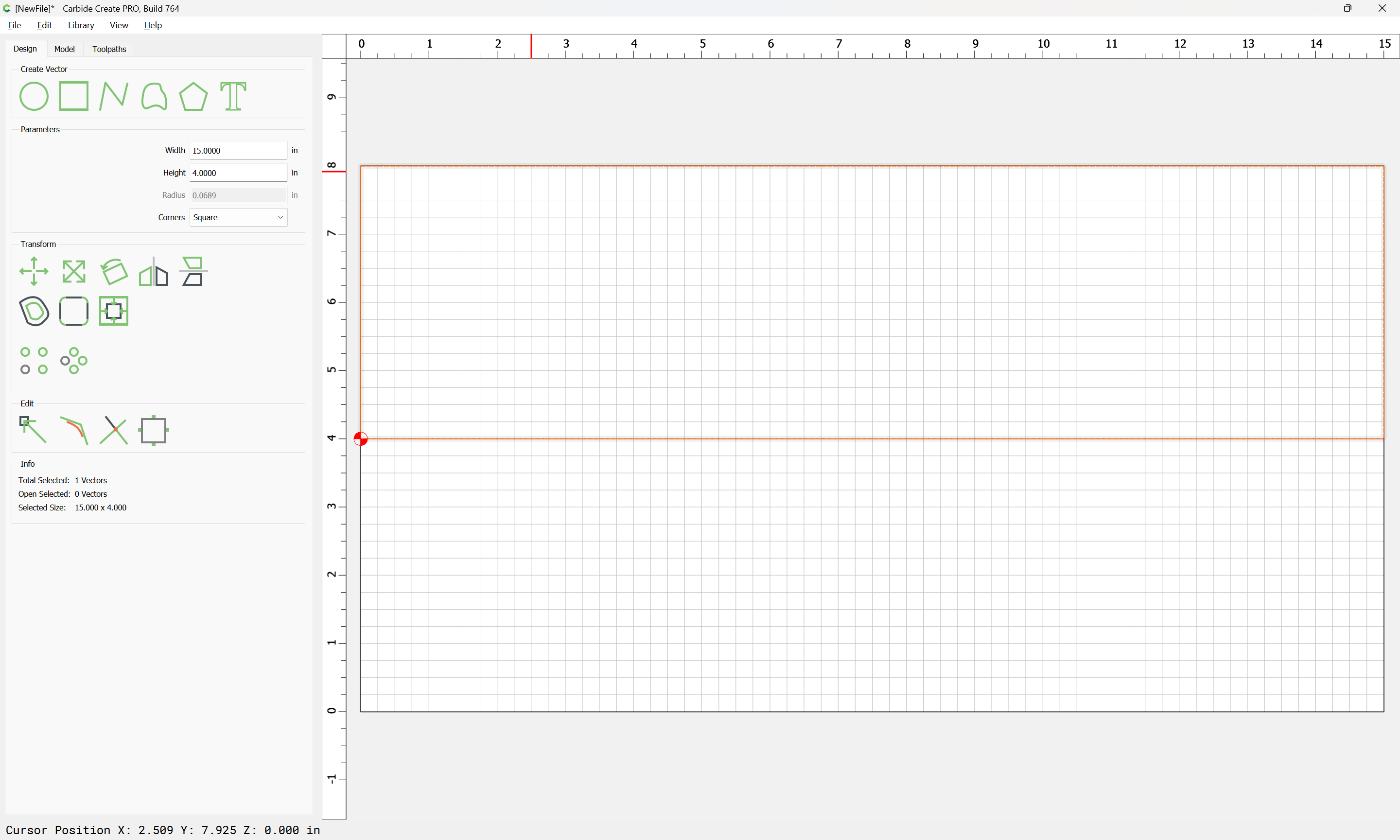
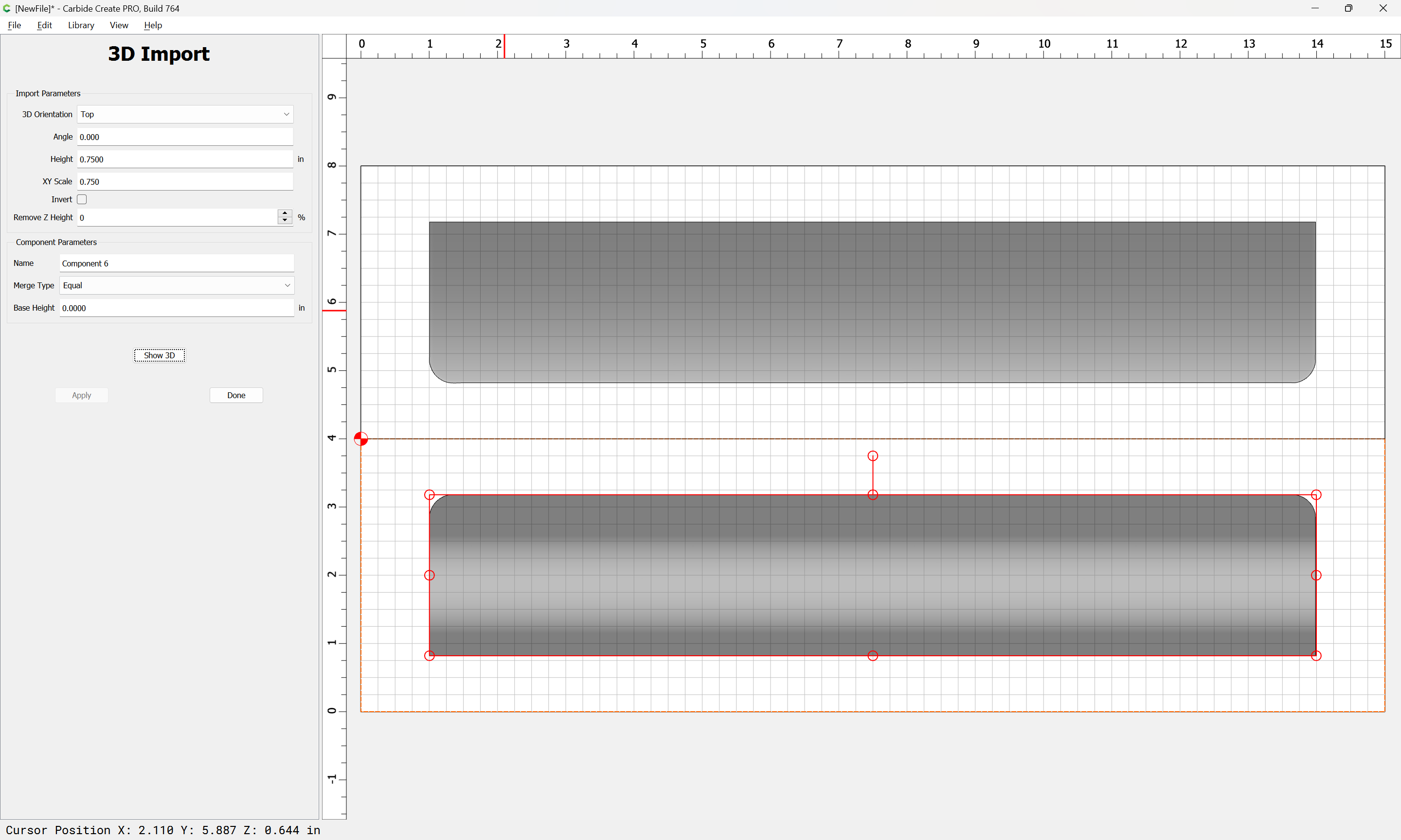
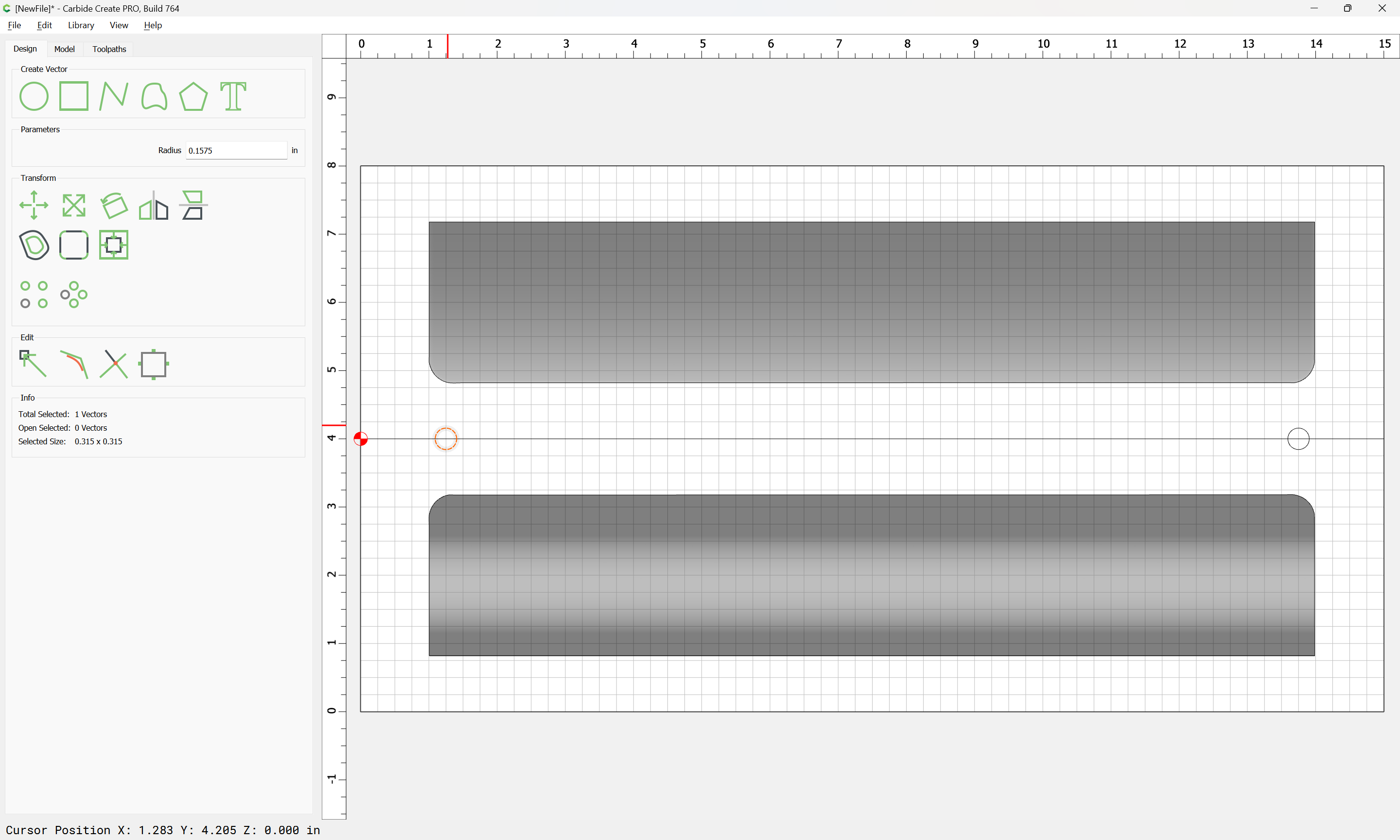
Note that they Y-axis is twice the specified dimension and that the origin is set to “Center-Left” — this is to facilitate setting the job up as two-sided.

Each half will be used for the upper or lower part of the wrist rest.

Draw in geometry for each half:

and import each side of the STL into each piece of geometry:

(since the stock is too small for a 1:1 import we will assume a 3/4-size keyboard and matching wrist rest)

Oddly the bottom doesn’t import as expected:

so we rotate the STL and save a copy of the rotated part:

and import that:

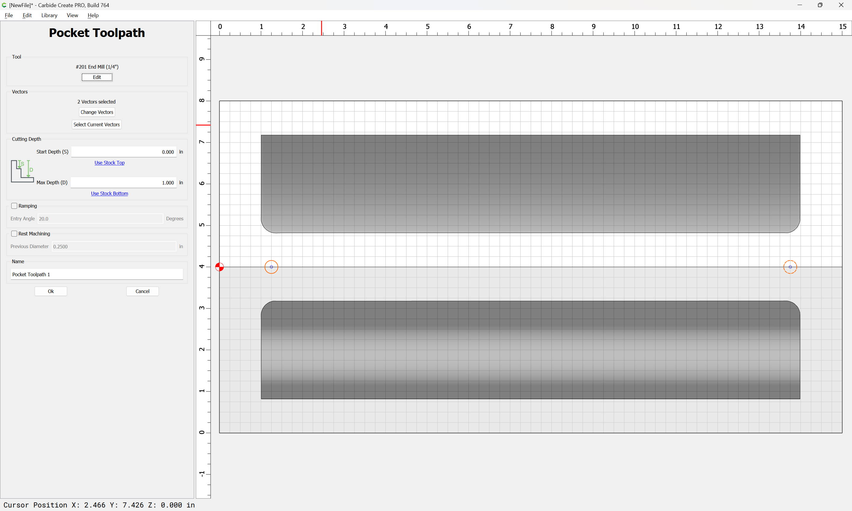
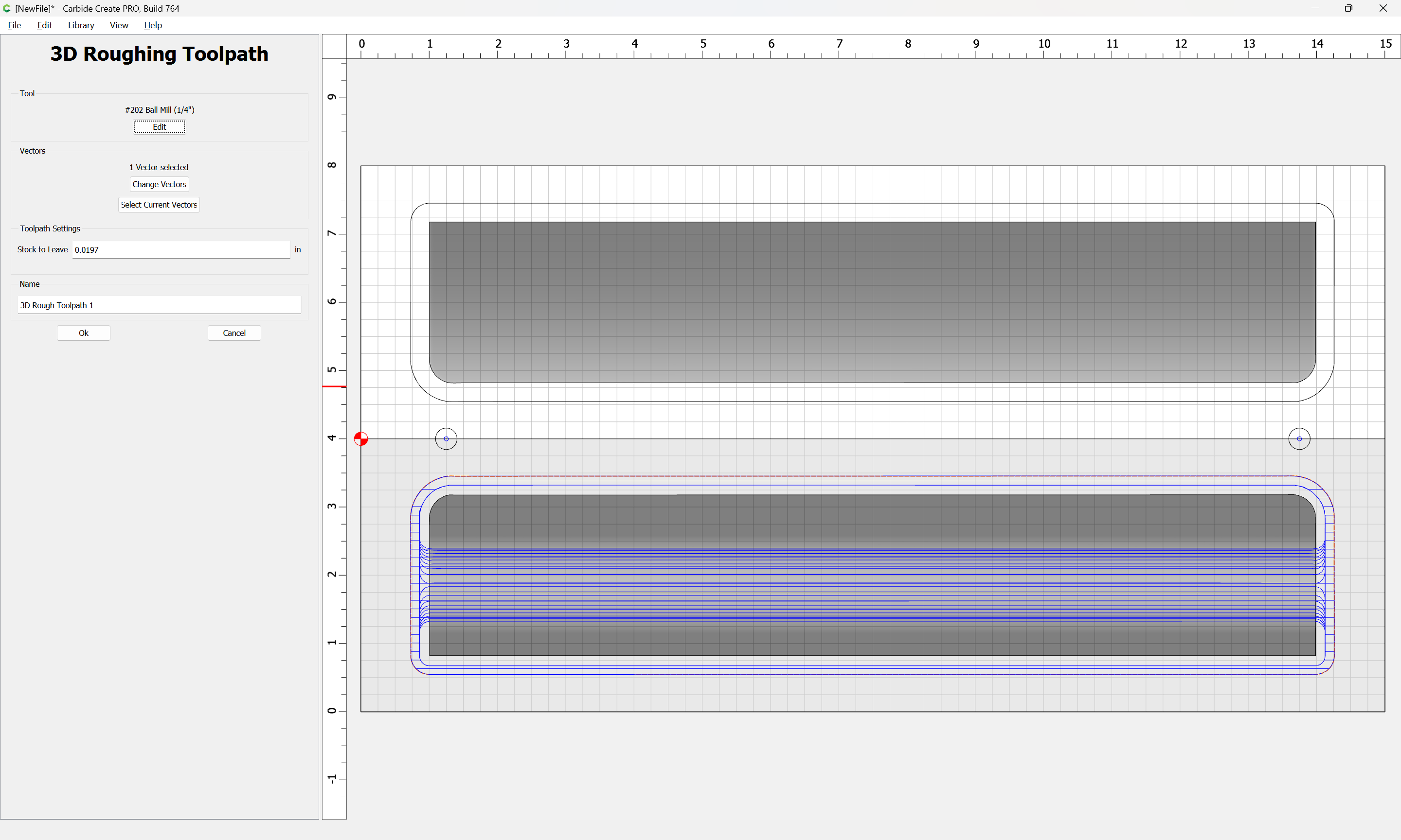
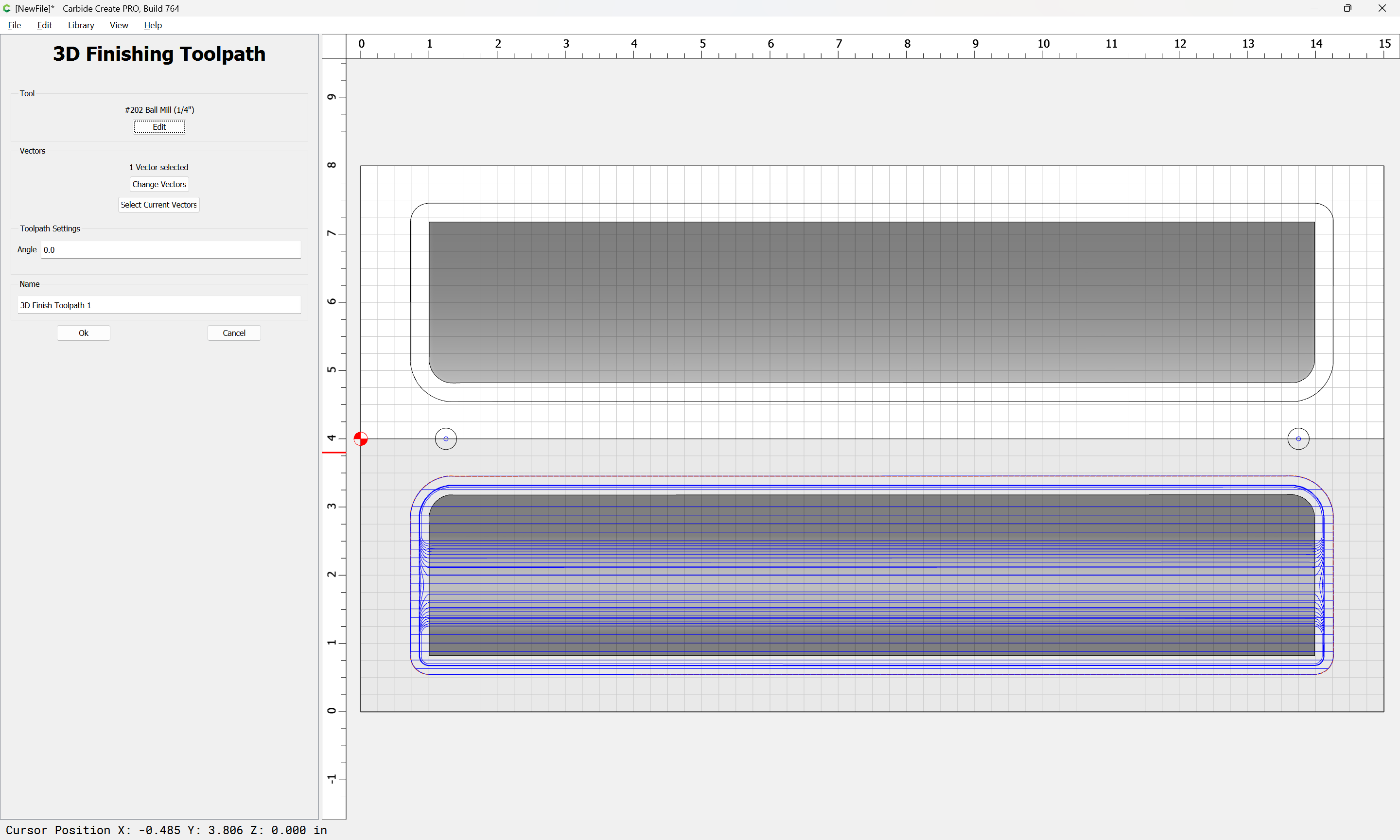
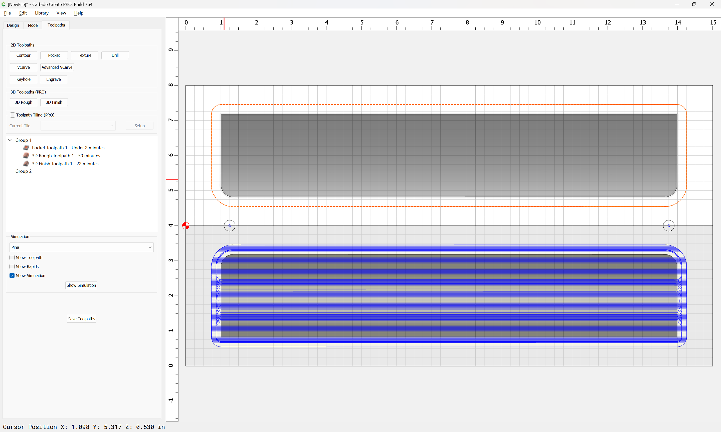
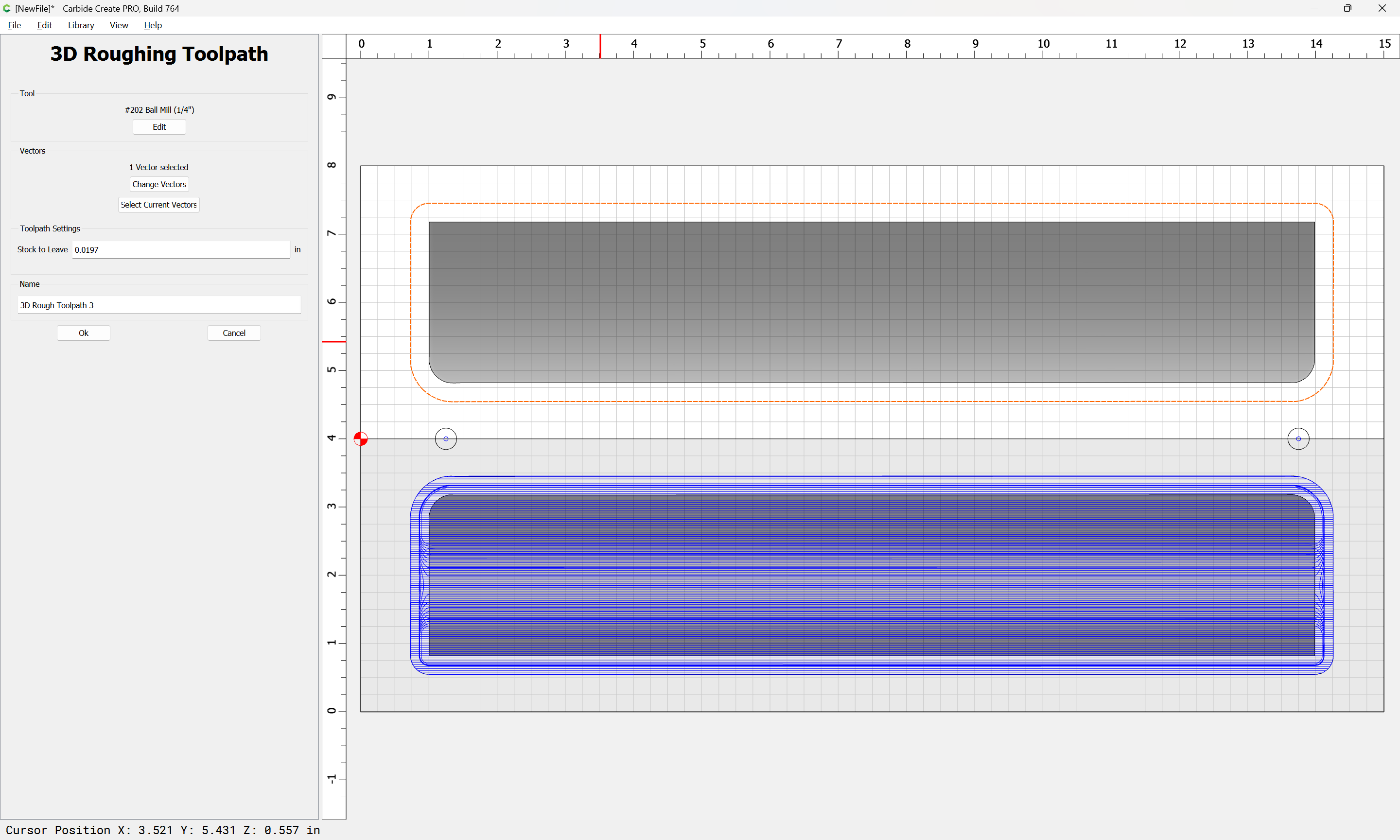
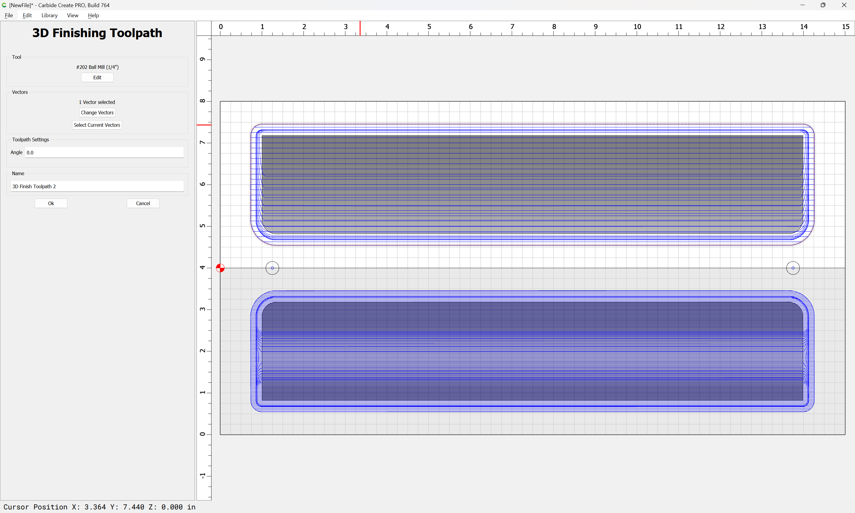
Next, it will be necessary to consider workholding and assign toolpaths.

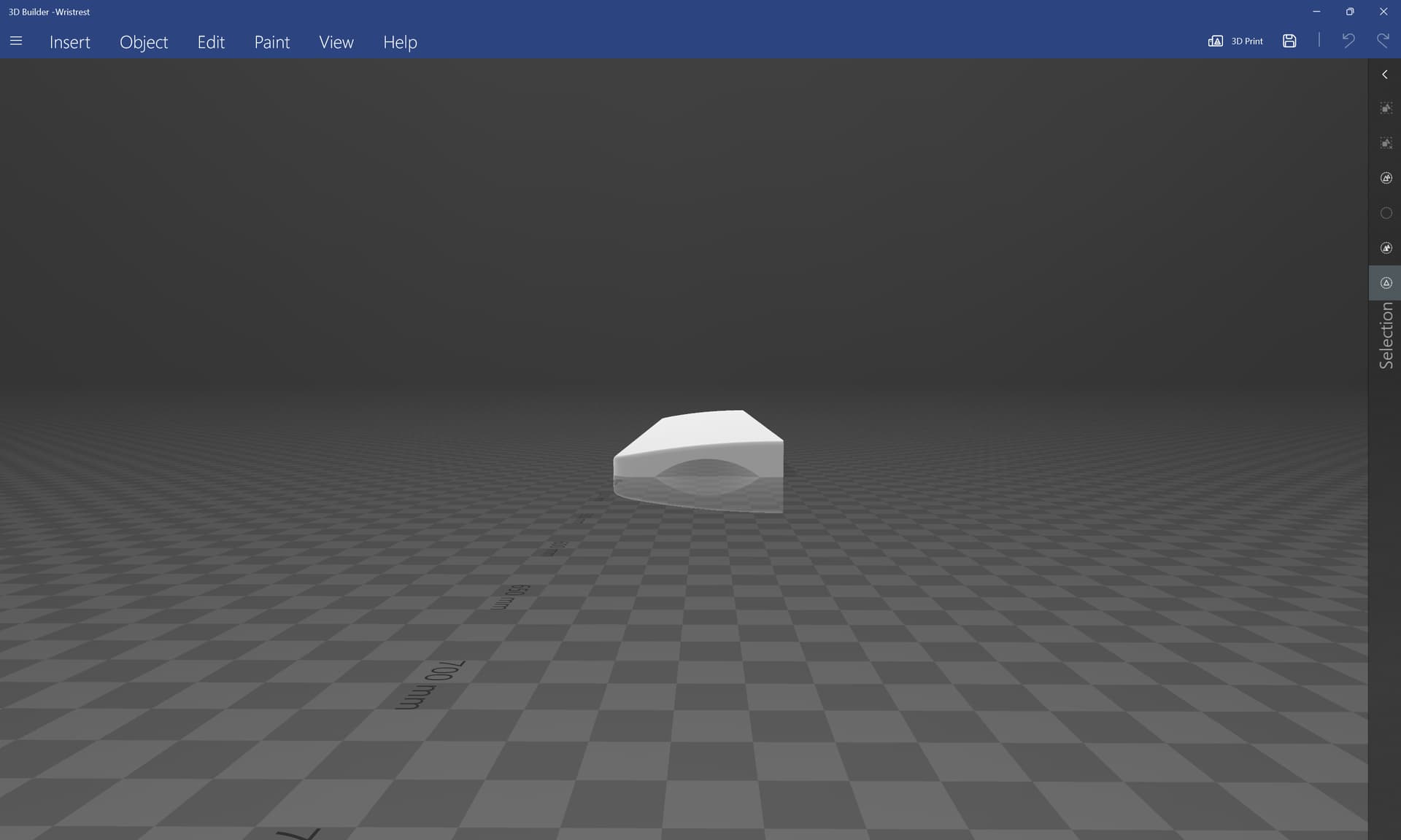
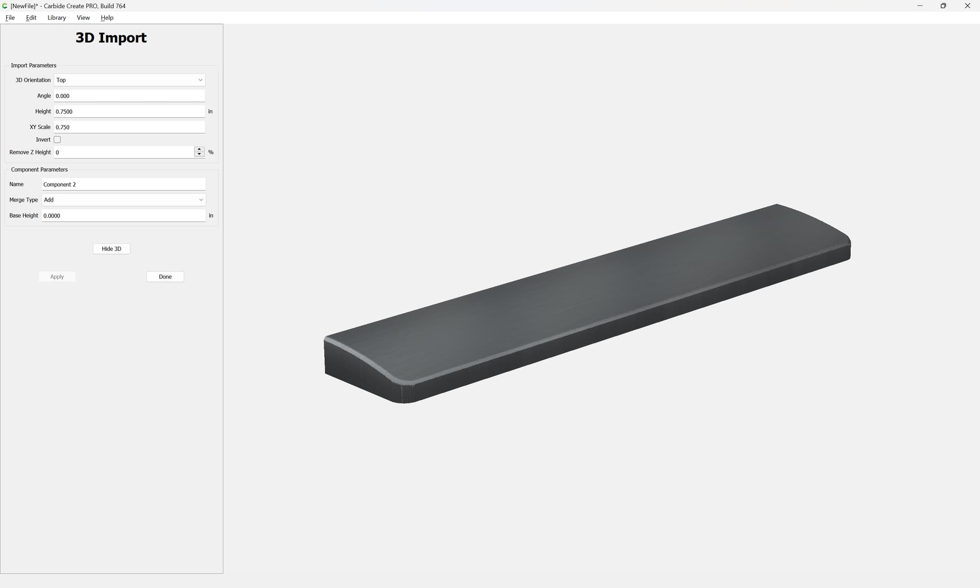
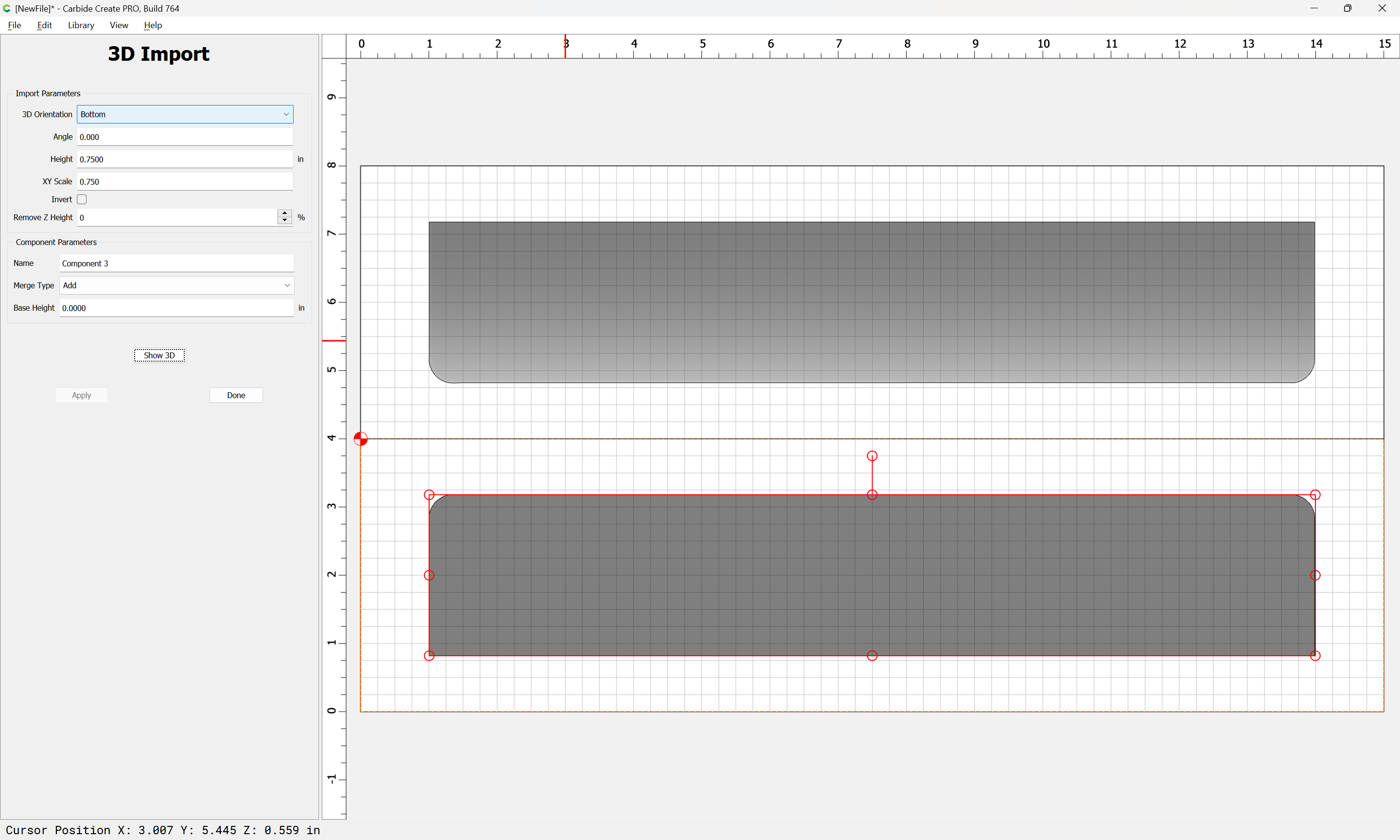
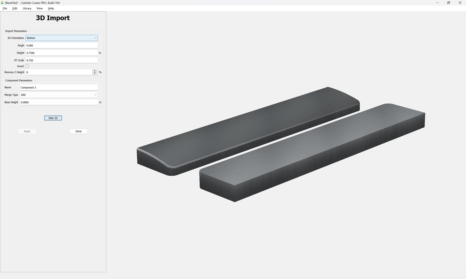
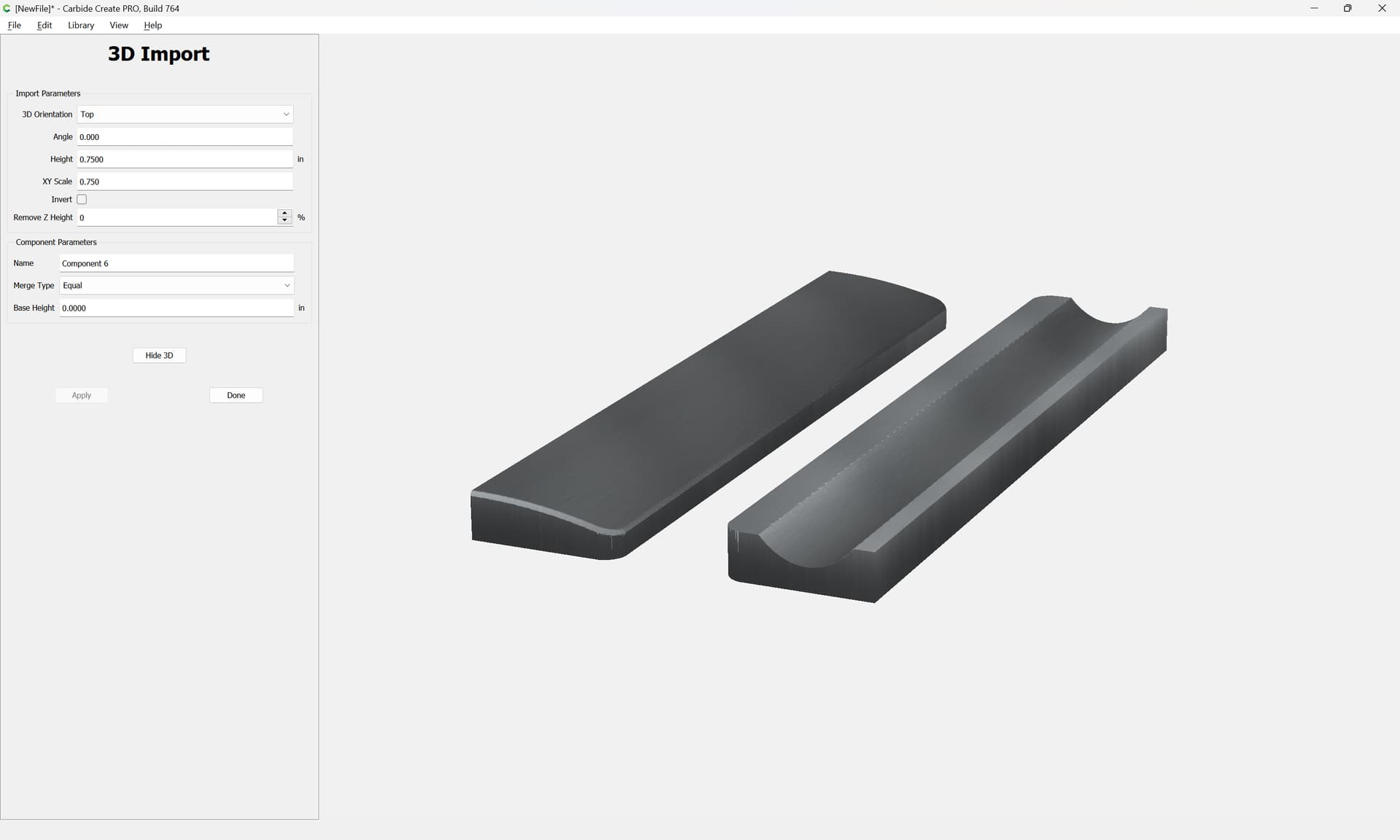
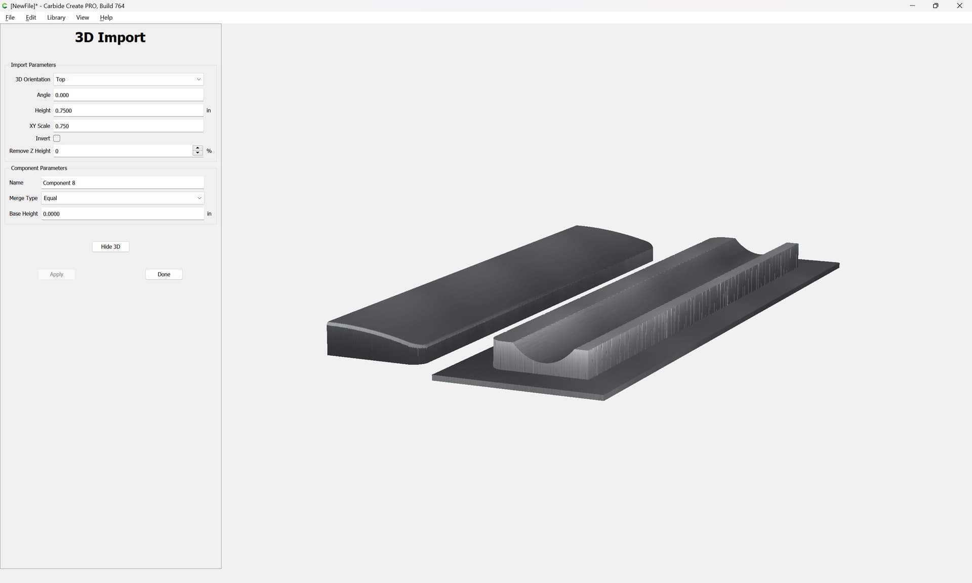
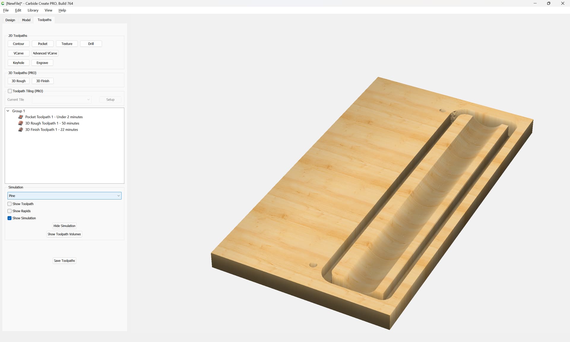
Since the wrist rest bottom has a flat bottom, we will cut that first, and then when rotating, affix that in place using double-sided tape or painter’s tape and cyanoacrylate:

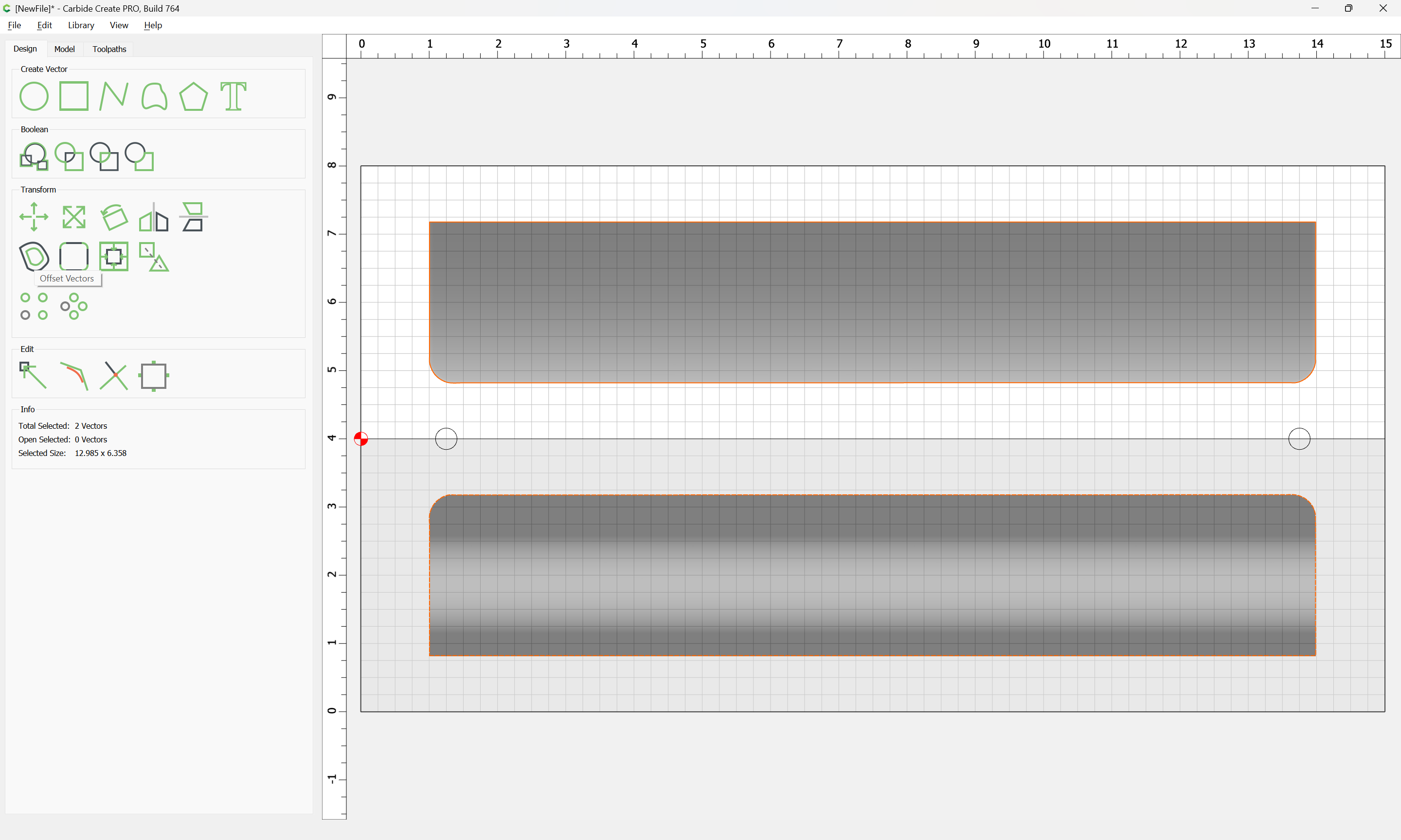
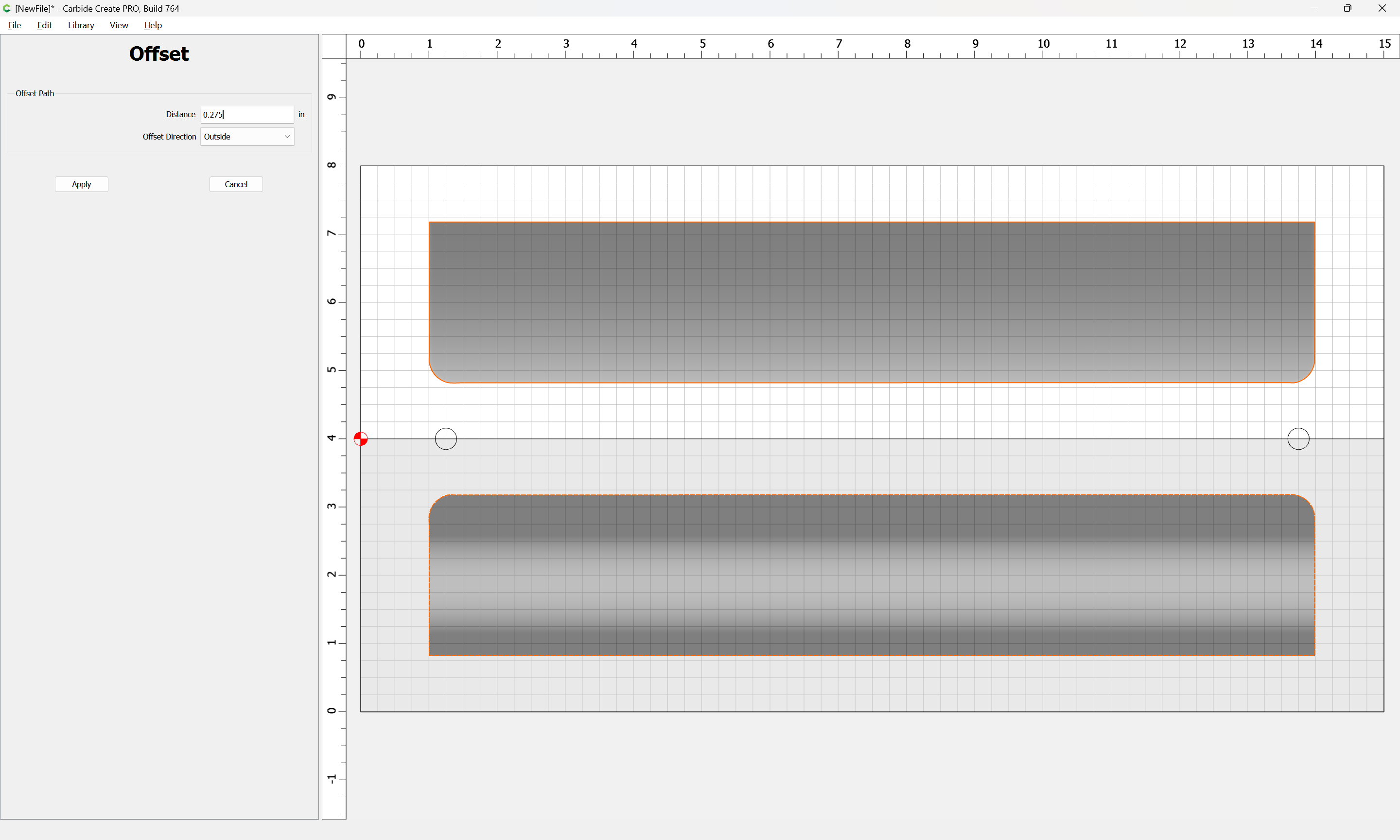
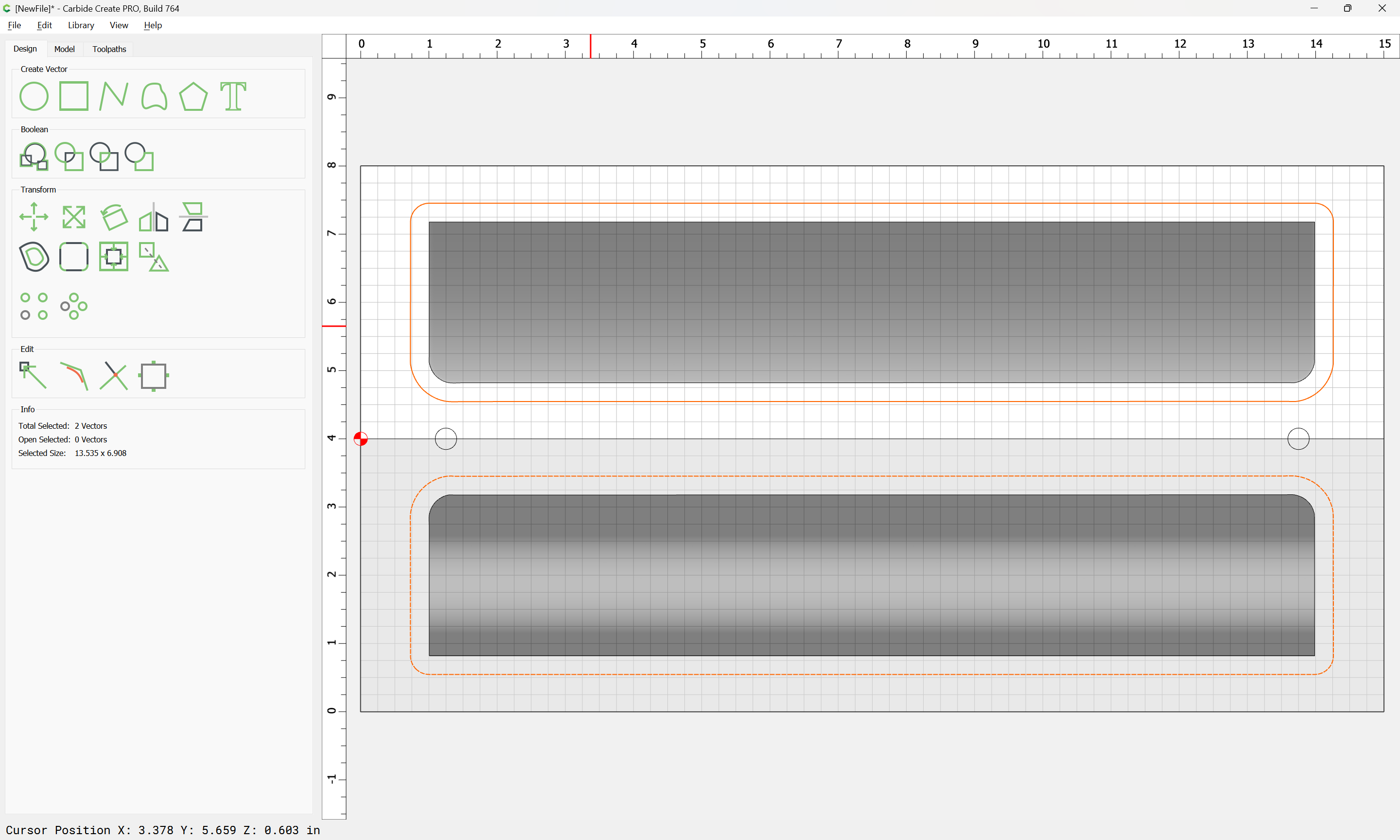
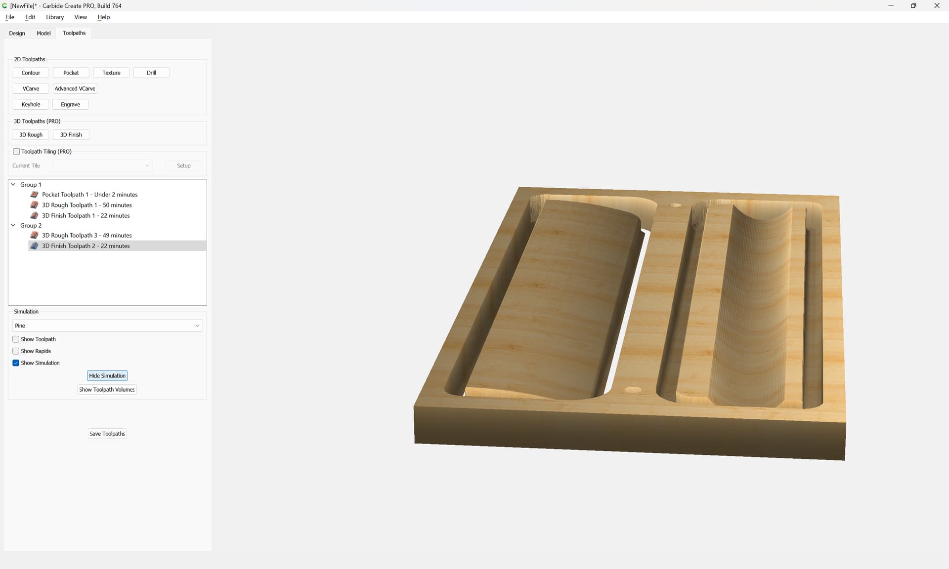
It will also be necessary to register the flip in some way — a pair of dowel holes should work well, say 5/16" (8mm):

Another consideration is that we won’t want to cut the part out completely, so we go back to the 3D modeling tab and add 1/8" of thickness:

(which will necessitate re-importing)

The first toolpaths will be for the dowels:

Then select the auto-traced geometries:

and offset them to the outside by the diameter of the endmill which will be used plus 10%:

Apply

Then assign a 3D Roughing toolpath to the bottom:

and then a 3D finishing toolpath:

(w/ a suitable stepover value)

Then, create a new group for the top:

and assign appropriate toolpaths there as well:

Disable the Group for the portion which is not being cut.

3 Likes

This topic was automatically closed 30 days after the last reply. New replies are no longer allowed.