Here’s a quick tutorial on doing this.
Start with an engineering drawing for a file you want to recreate, we’ll use the filler strips from:
and open the PDF:
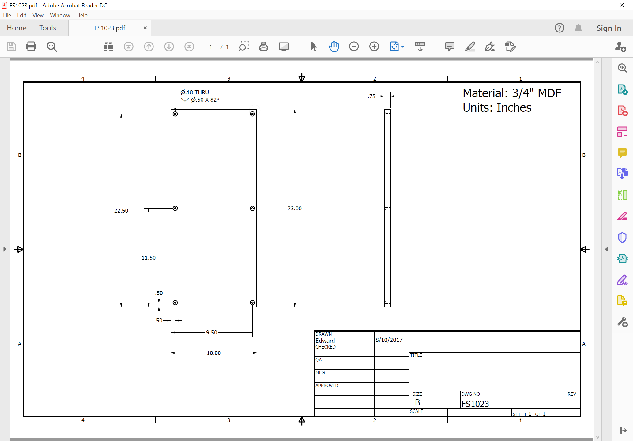
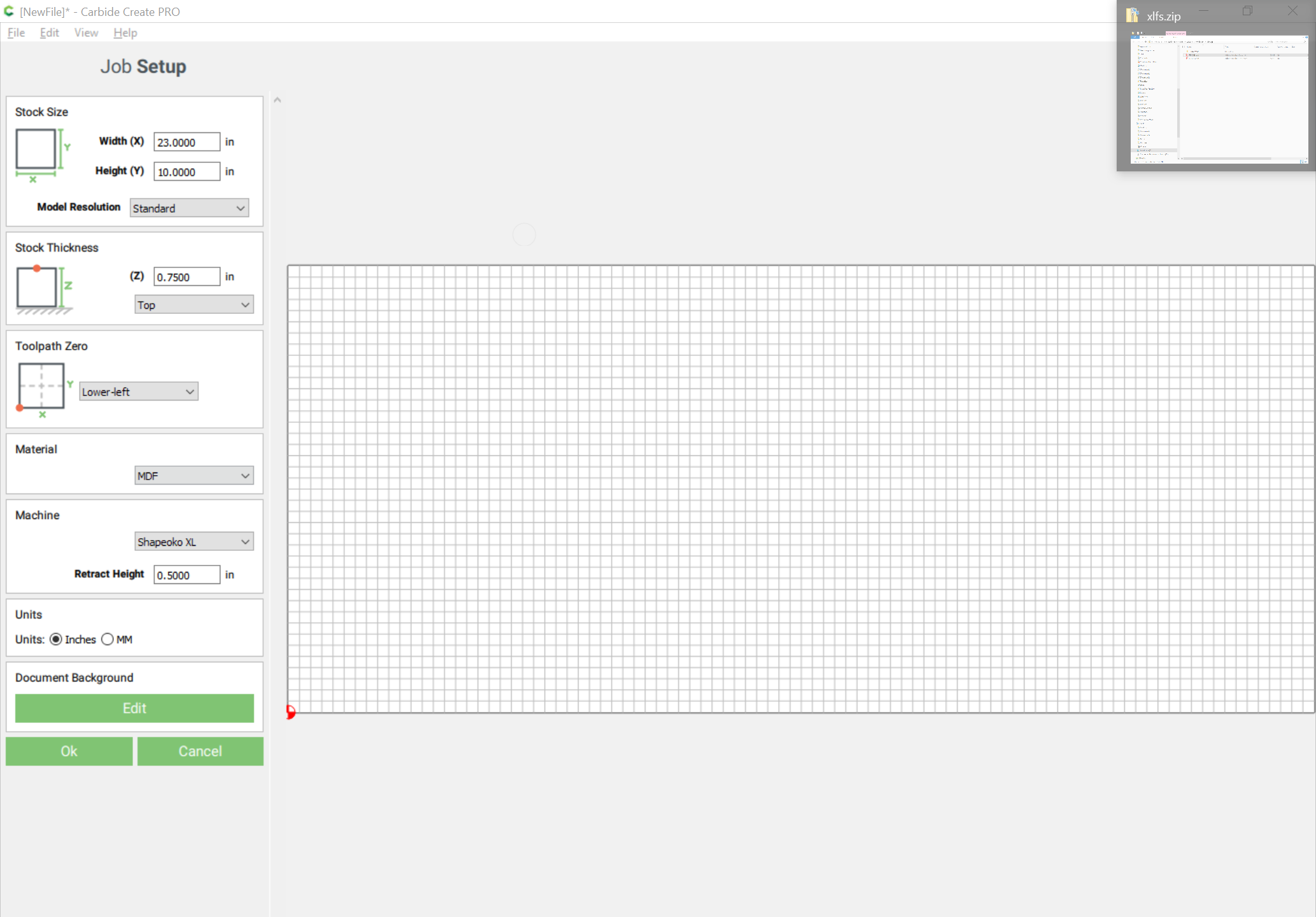
Note the thickness (0.75 inches) and width (10 inches) and depth (23 inches) and transfer it into job setup — note that width and depth will need to be transposed — and set the material and retract height:
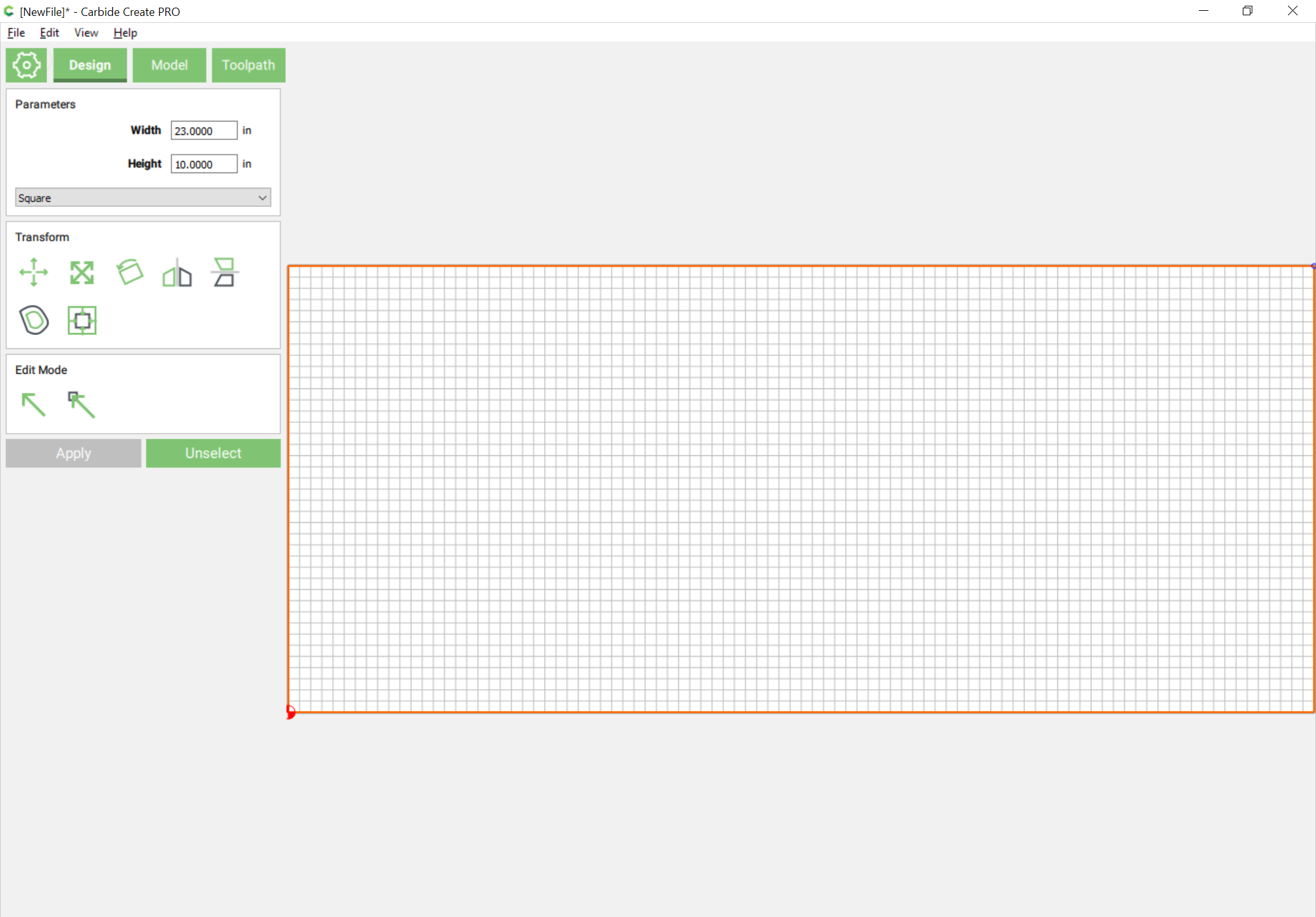
Draw a rectangle:
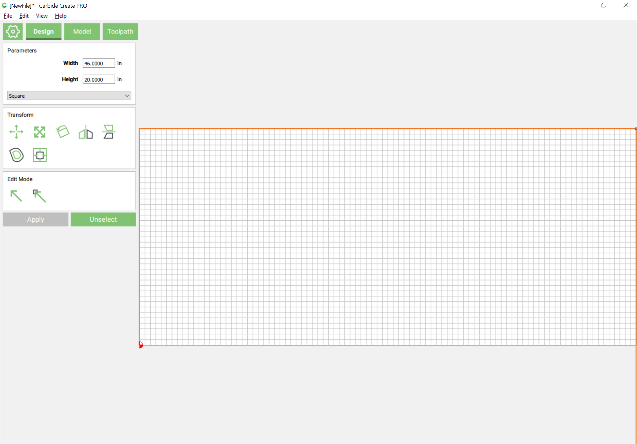
Note that since Carbide Create draws from the center out it is easiest to draw one which is twice the desired size and then reduce to half the original size to get the desired size (alternately, put the origin at the center and begin drawing there). If need be, drag into position.
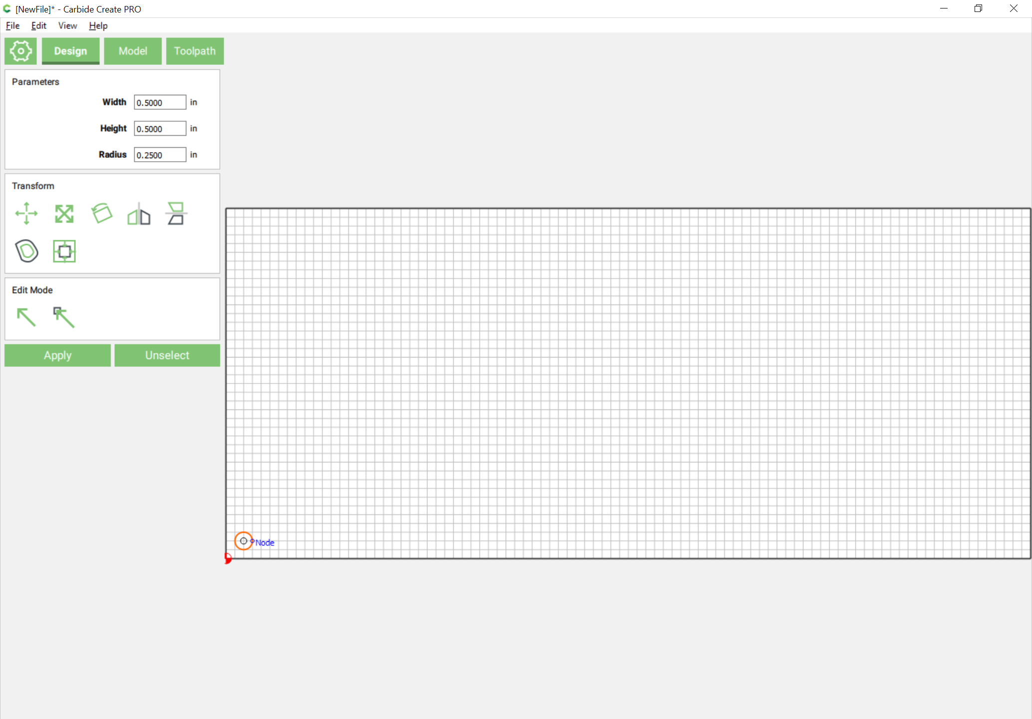
From the drawing note that the center of the holes are 0.5" in from the corners — draw a hole on that center at each corner using the Circle tool:

and then select it change the radius to make a hole of the desired diameter:

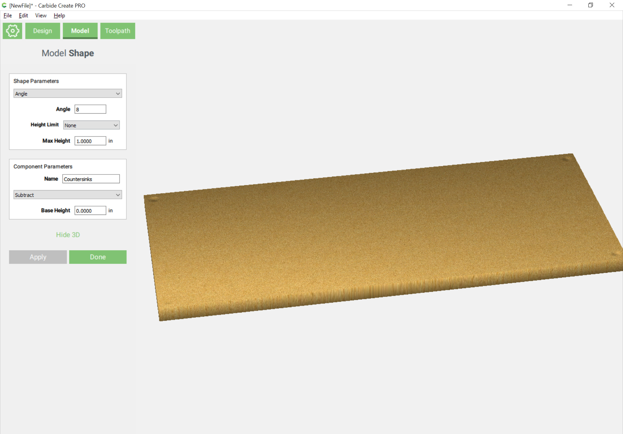
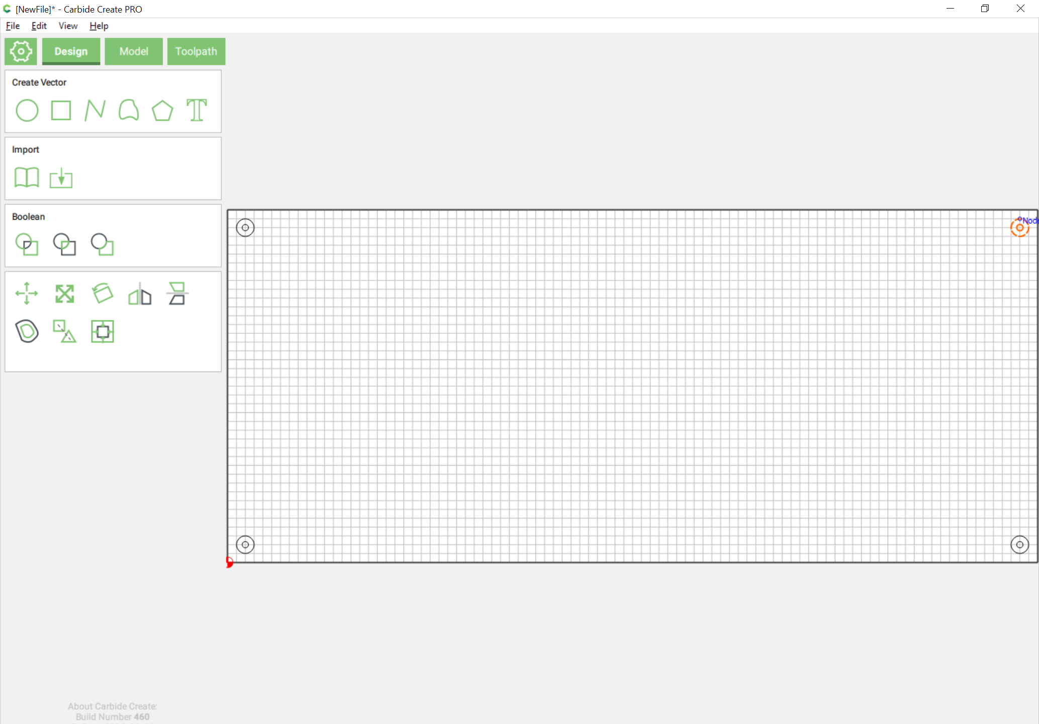
Redraw the hole for the chamfer/countersink:
and duplicate the twain and drag them into position at each corner:
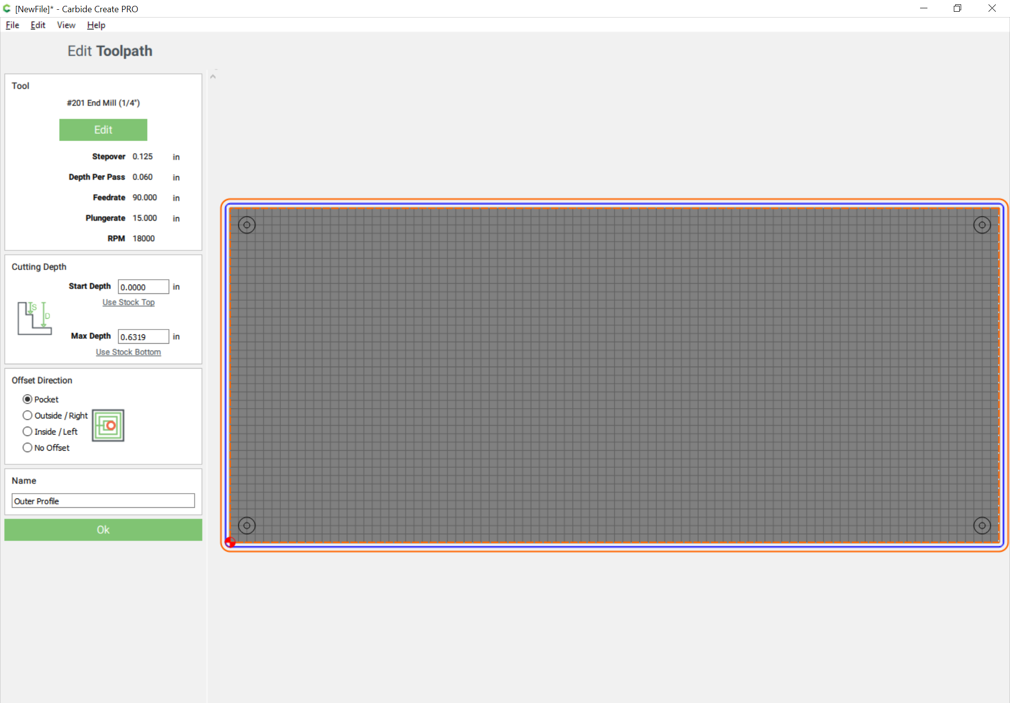
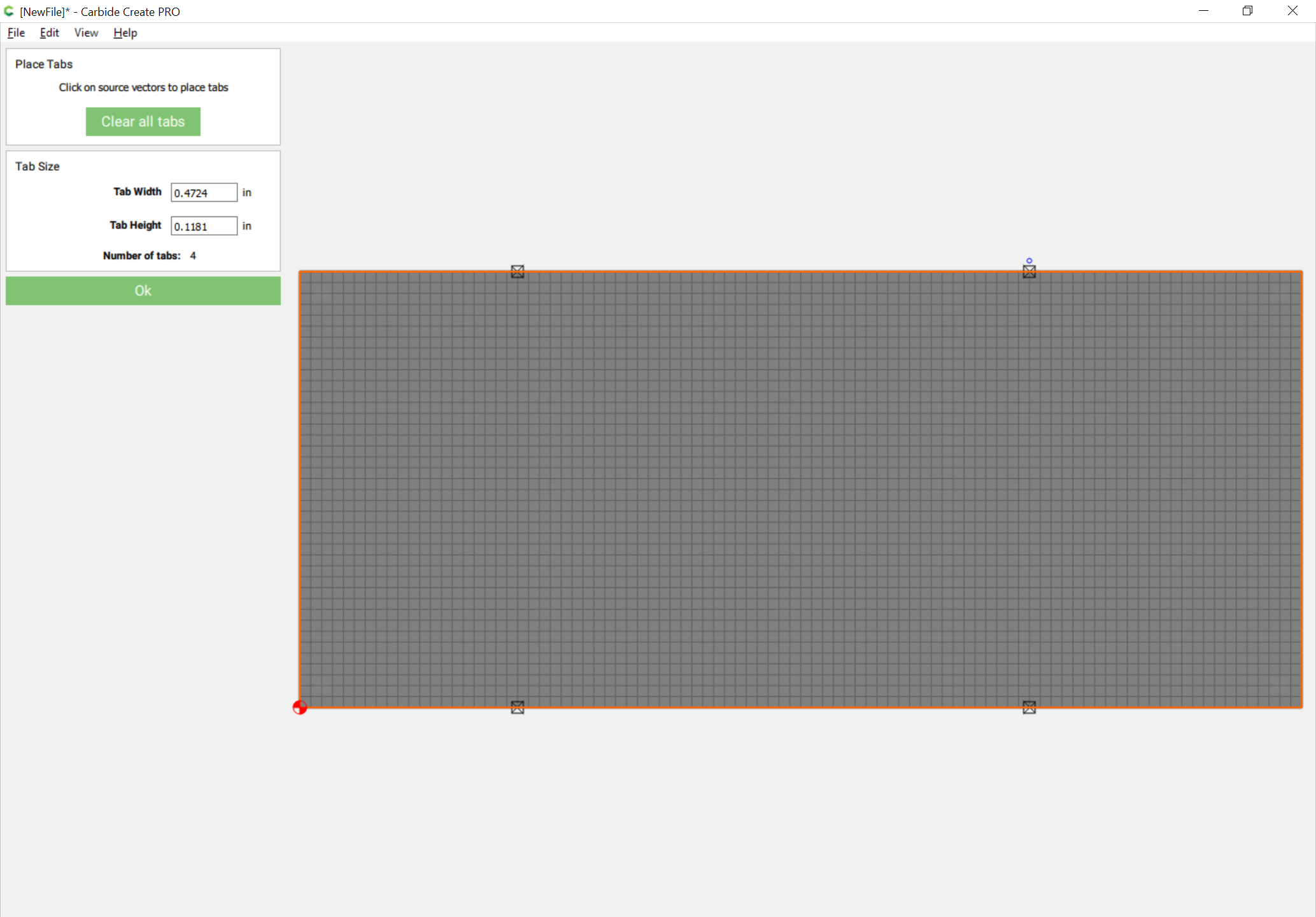
Before going to make toolpaths note that the thickness would be tough to cut as a slot, so add geometry around the perimeter a bit more than 10% of the diameter of the endmill, a #201 will be used, so 0.275 inches:
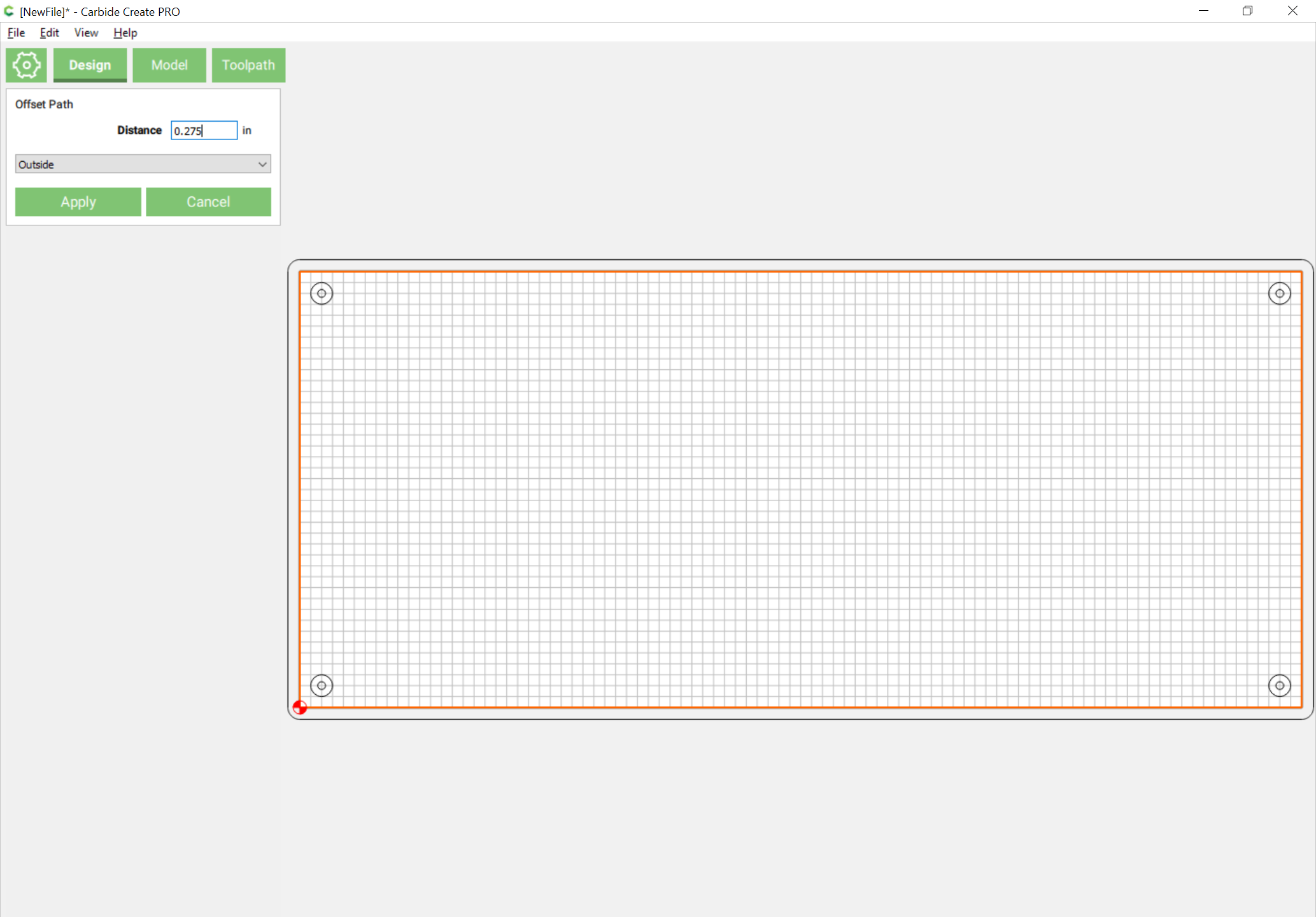
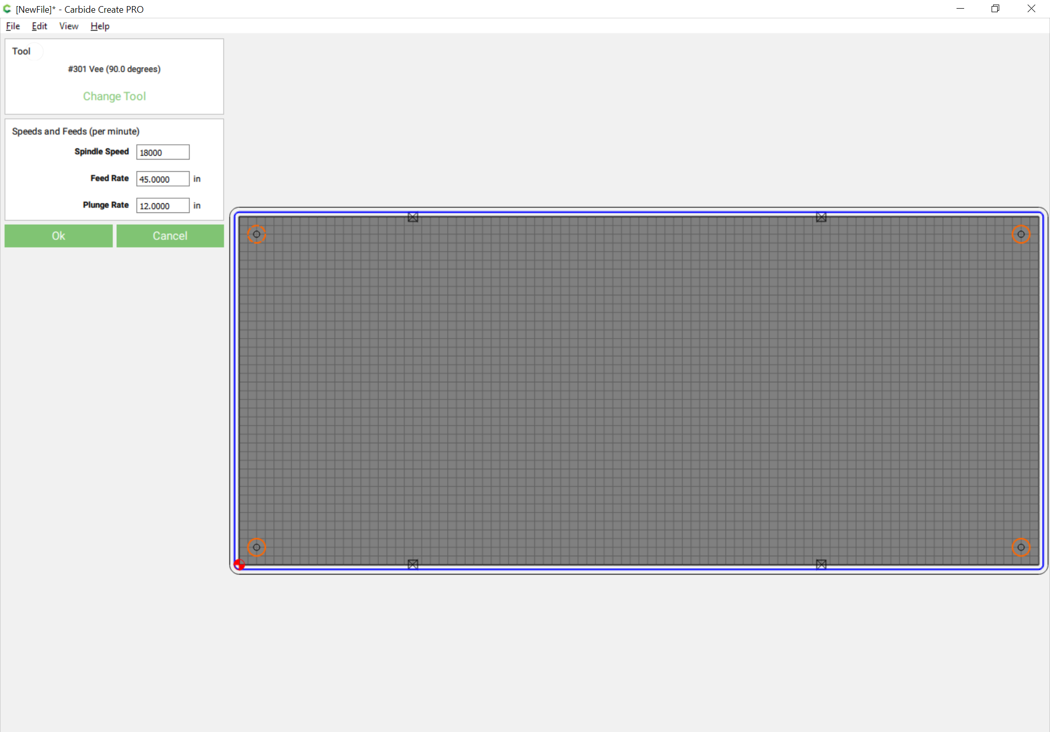
With everything drawn up, it’s time for toolpaths.