Making Shapes and 3D Contours

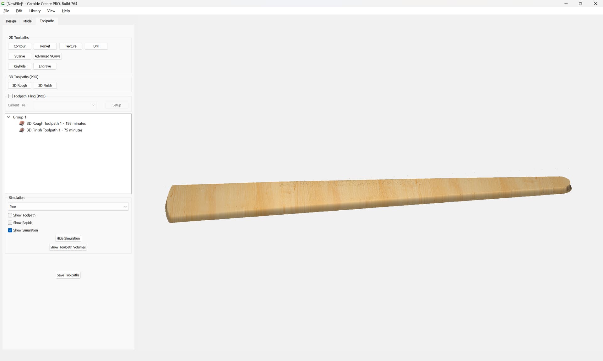
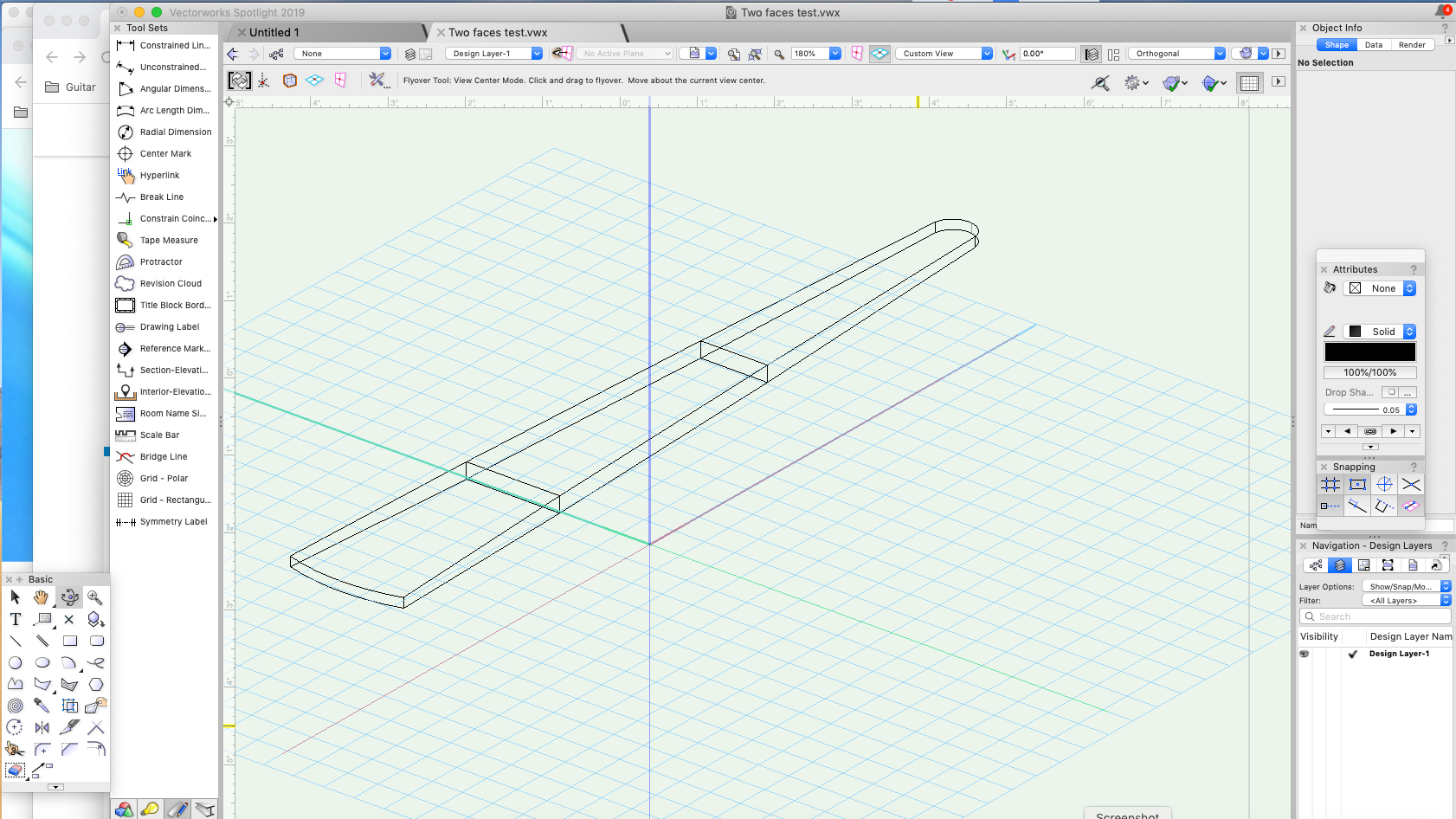
Hi Will, Now that I’ve got the model done, how to I actually machine it? LOL. I know I’ve got to flip it over to do both sides but that’s all I understand.

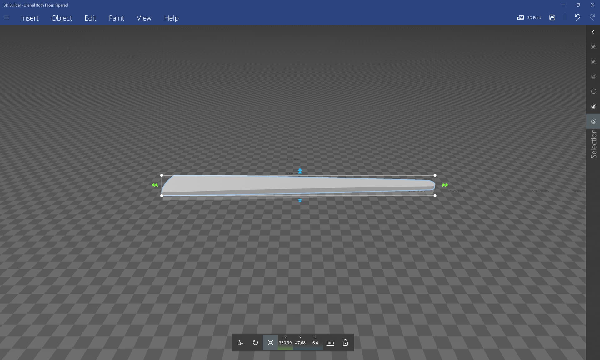
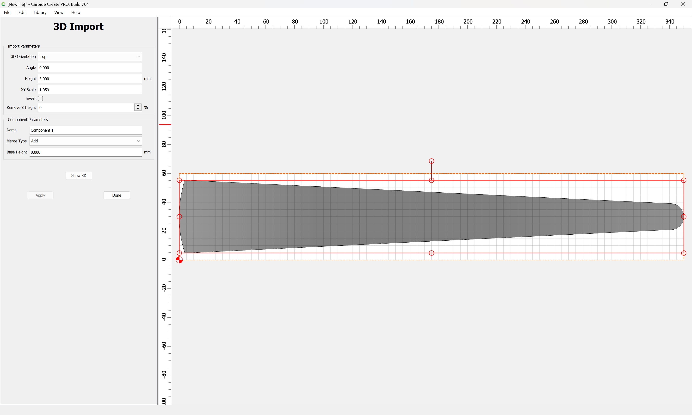
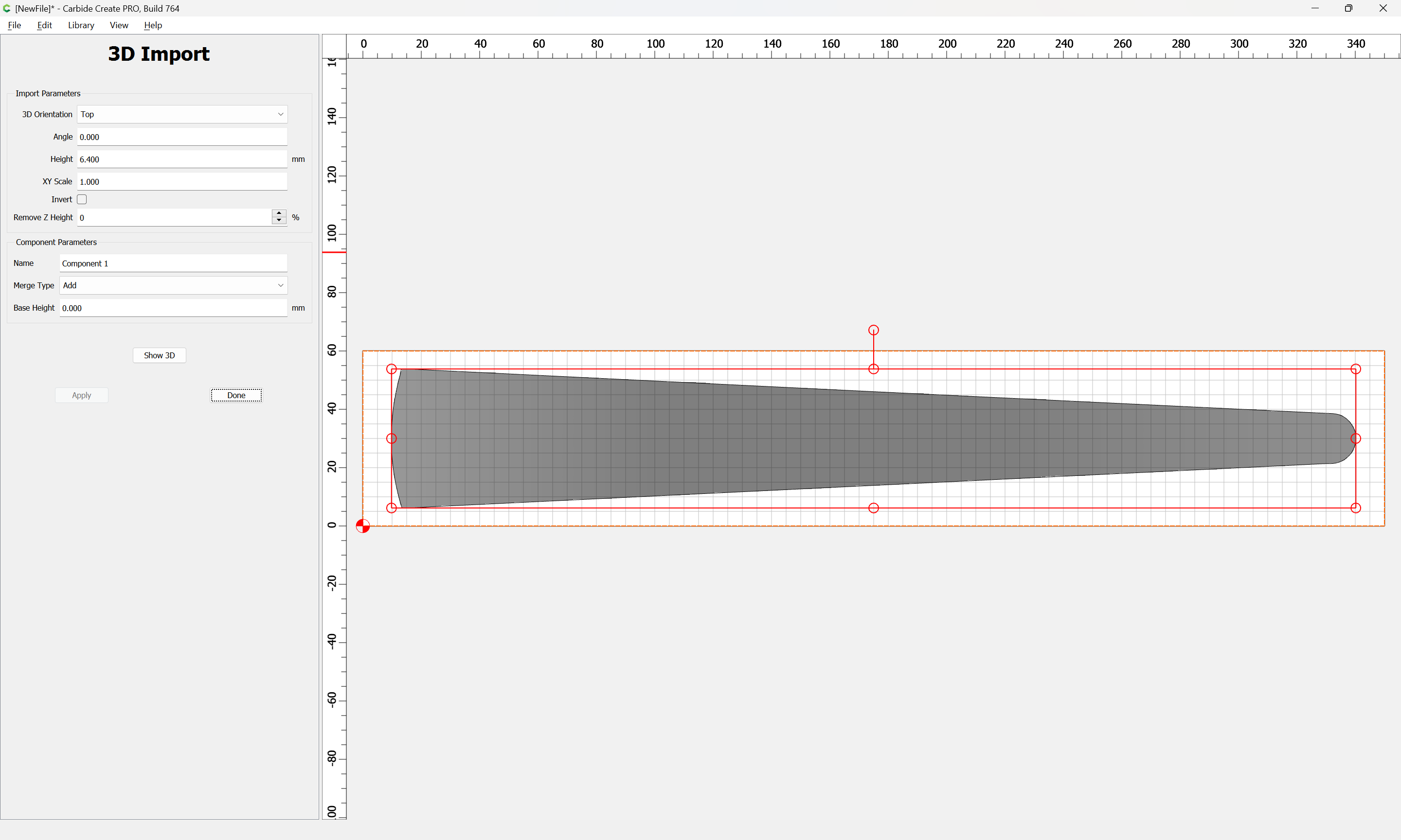
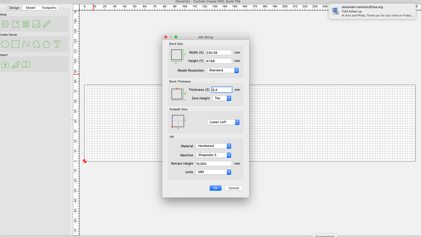
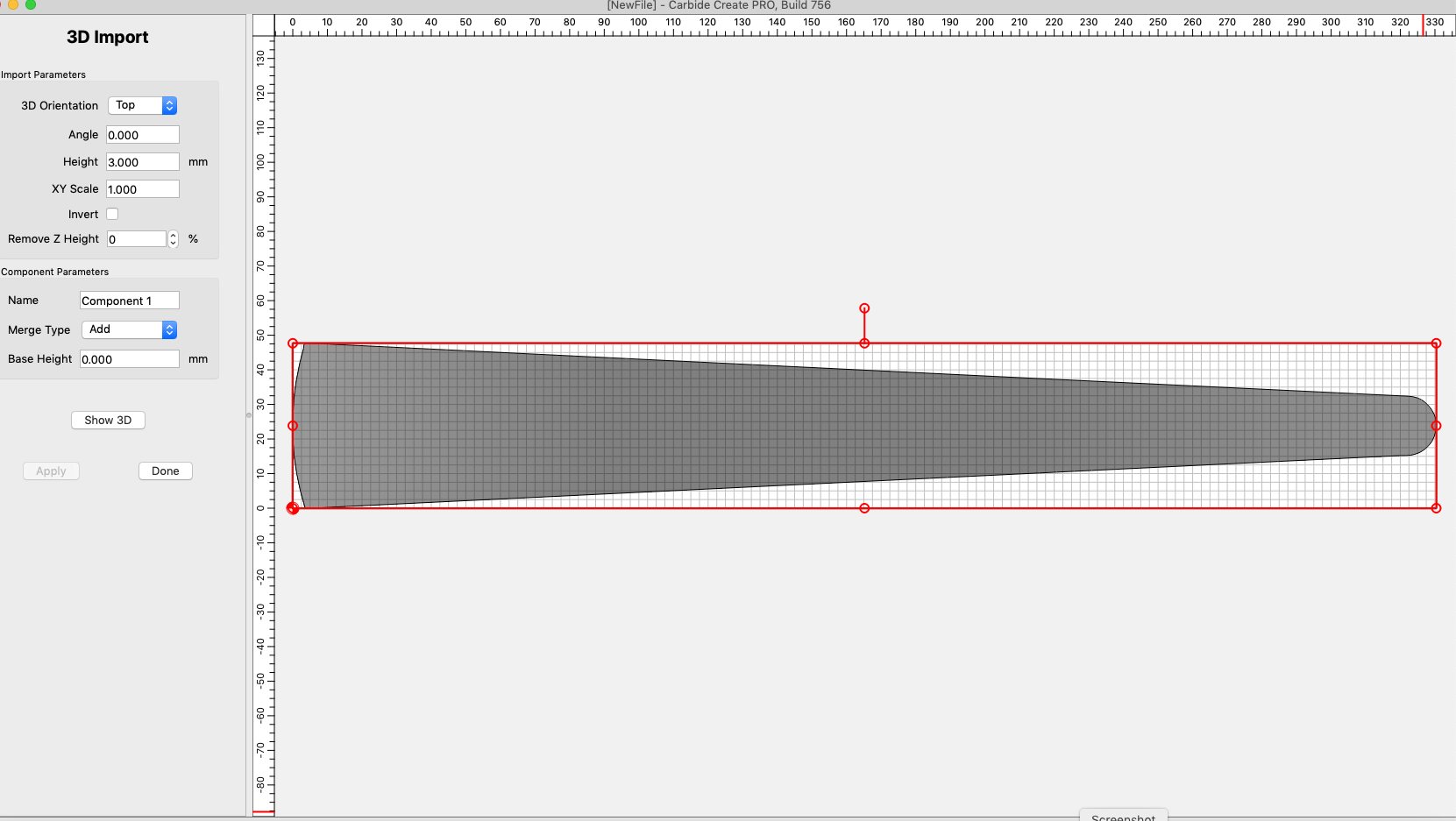
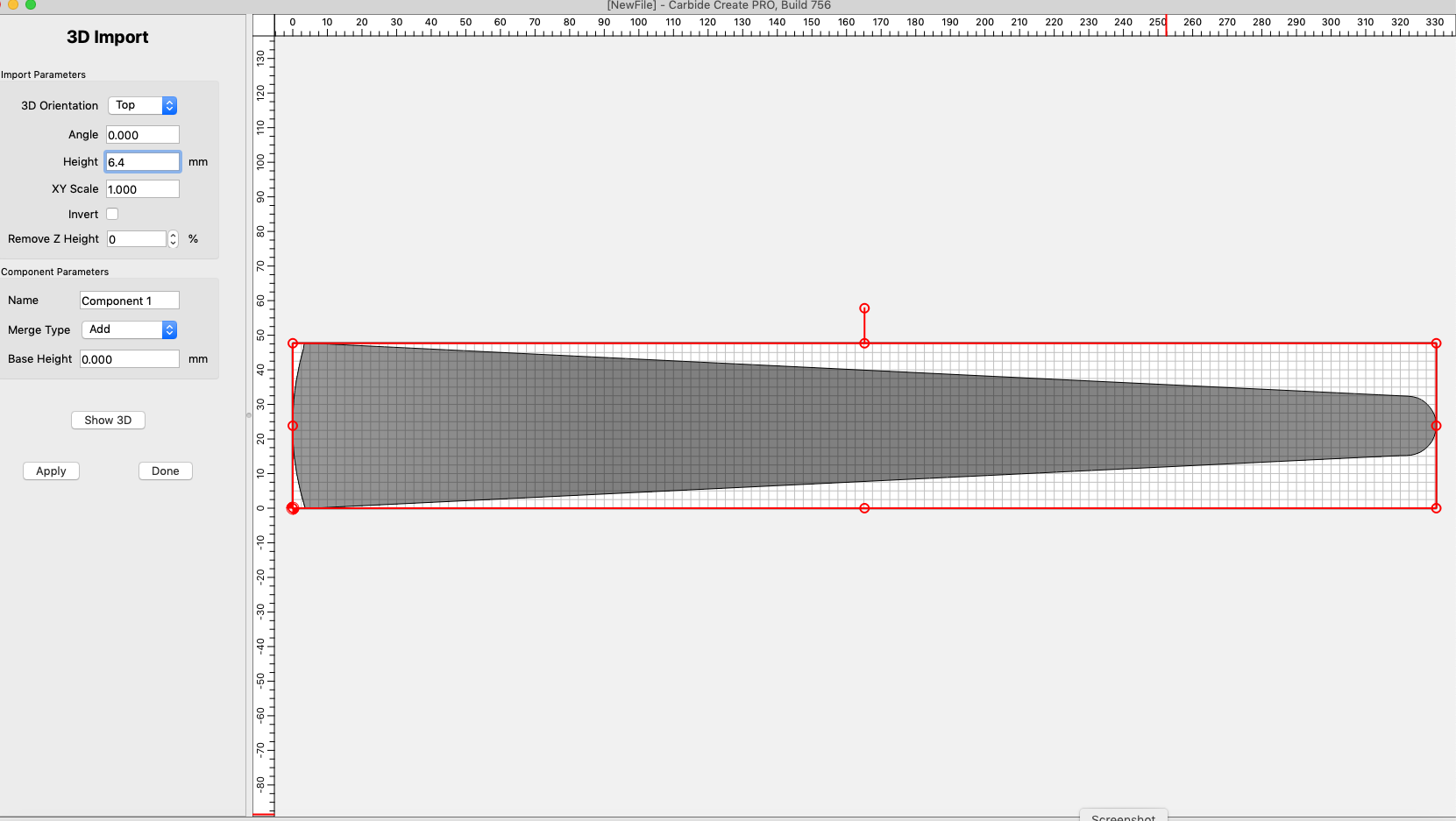
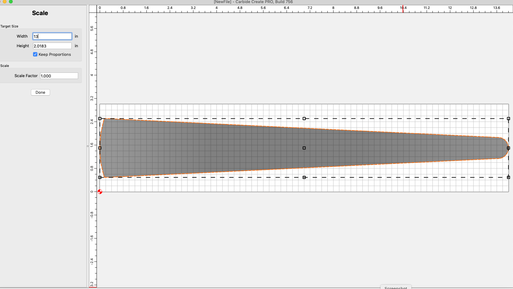
In VWX it’s 13 inches long. When I import it, I see in the import box, there’s a height of .1181 and the XY scale imports as 1.076 for some reason. What do those mean? Is it scaling to match the stock size, which is set at 14"?


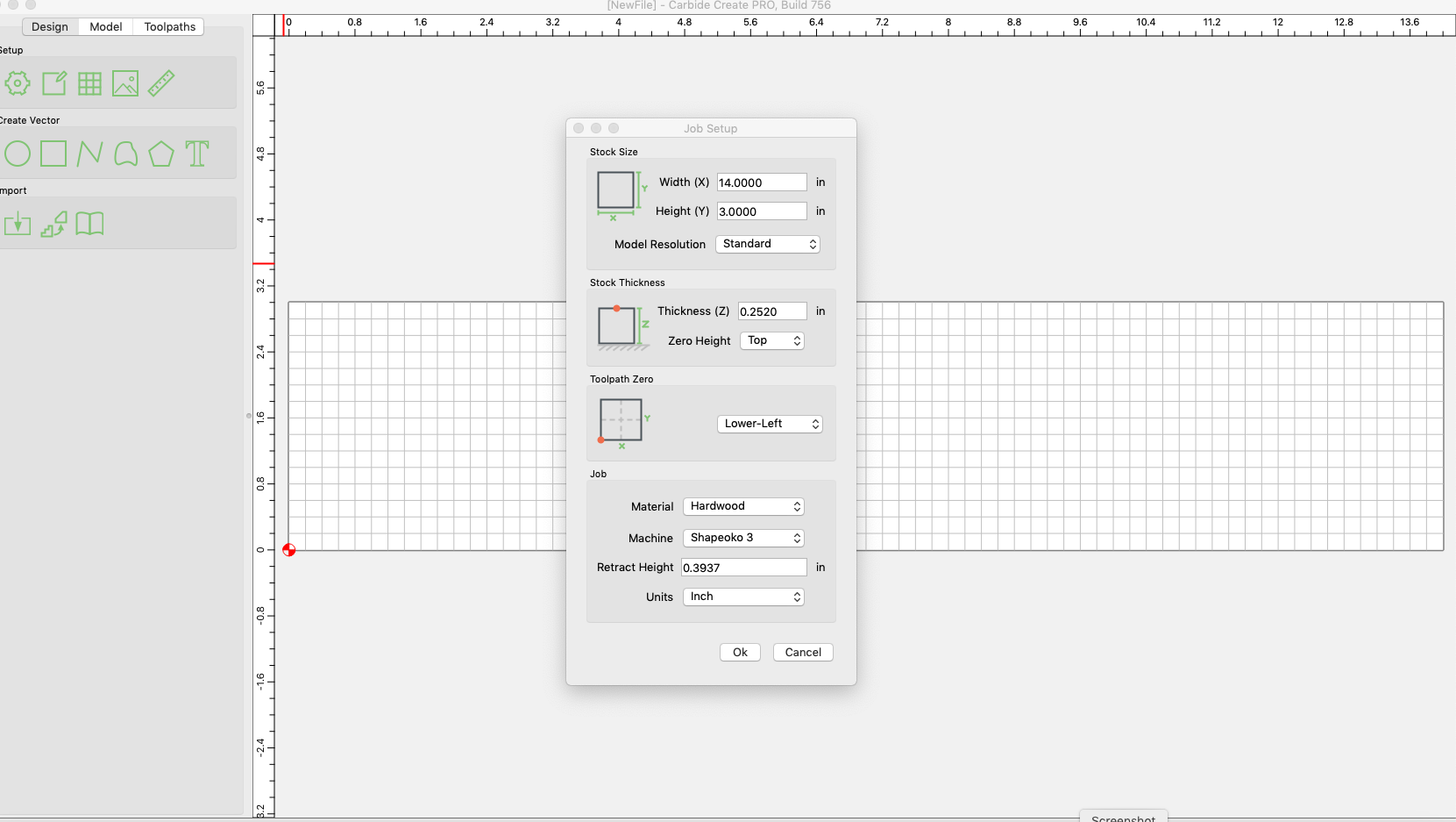
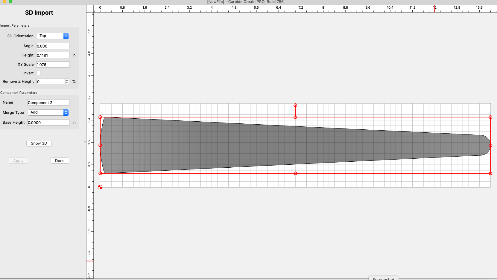
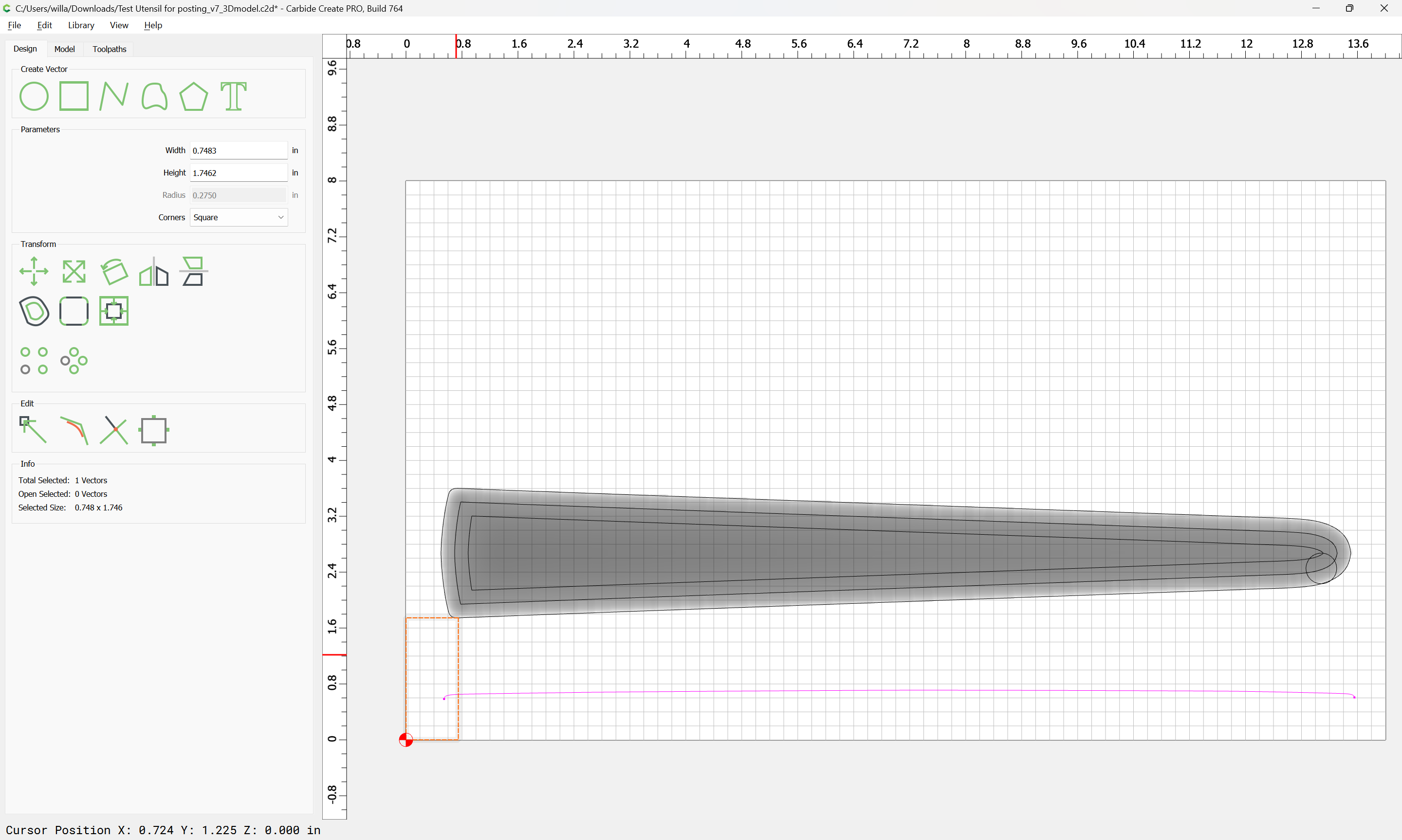
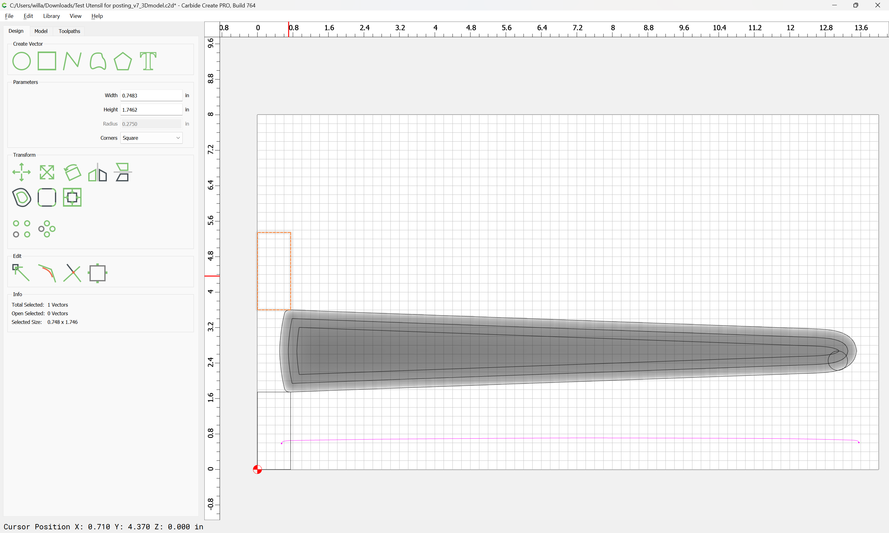
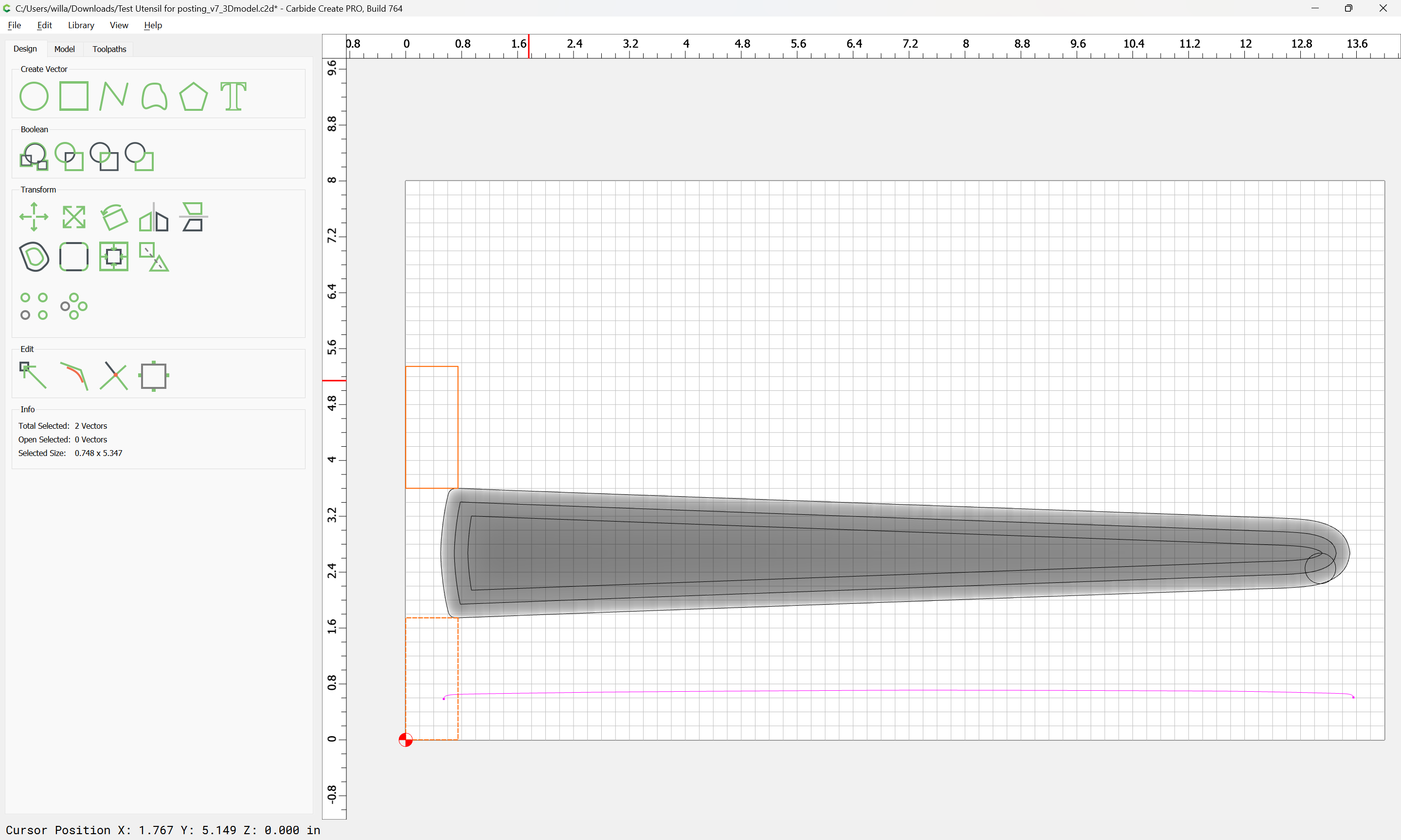
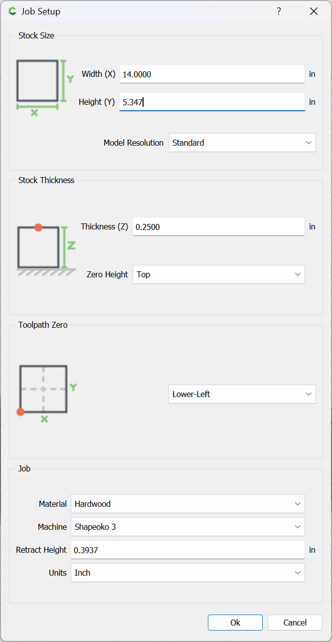
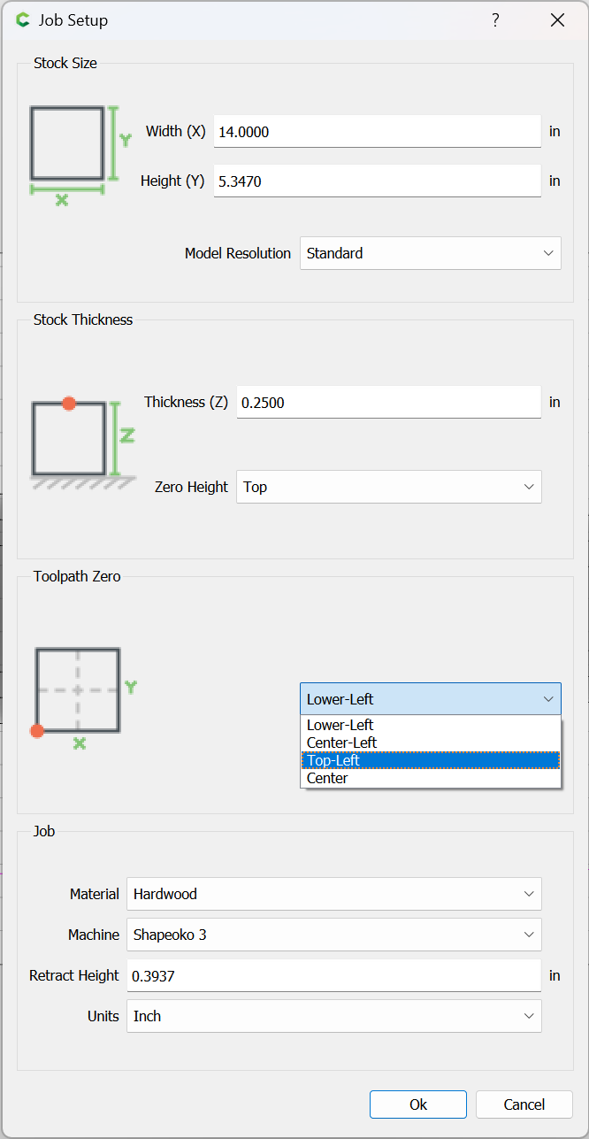
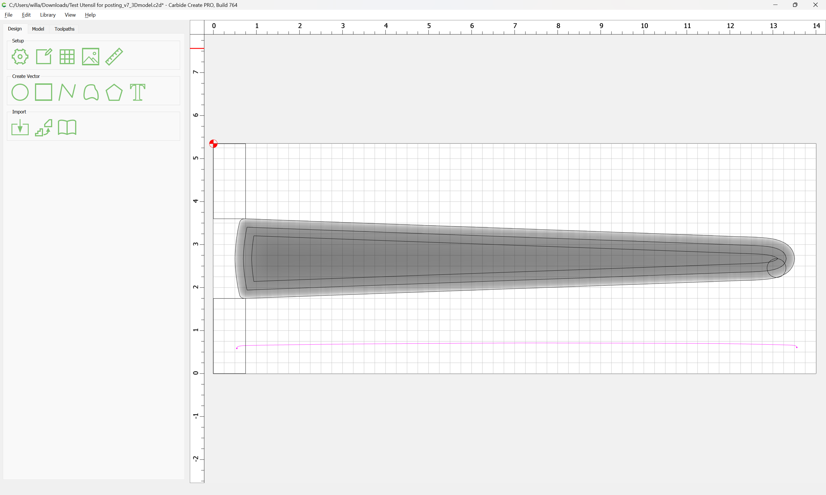
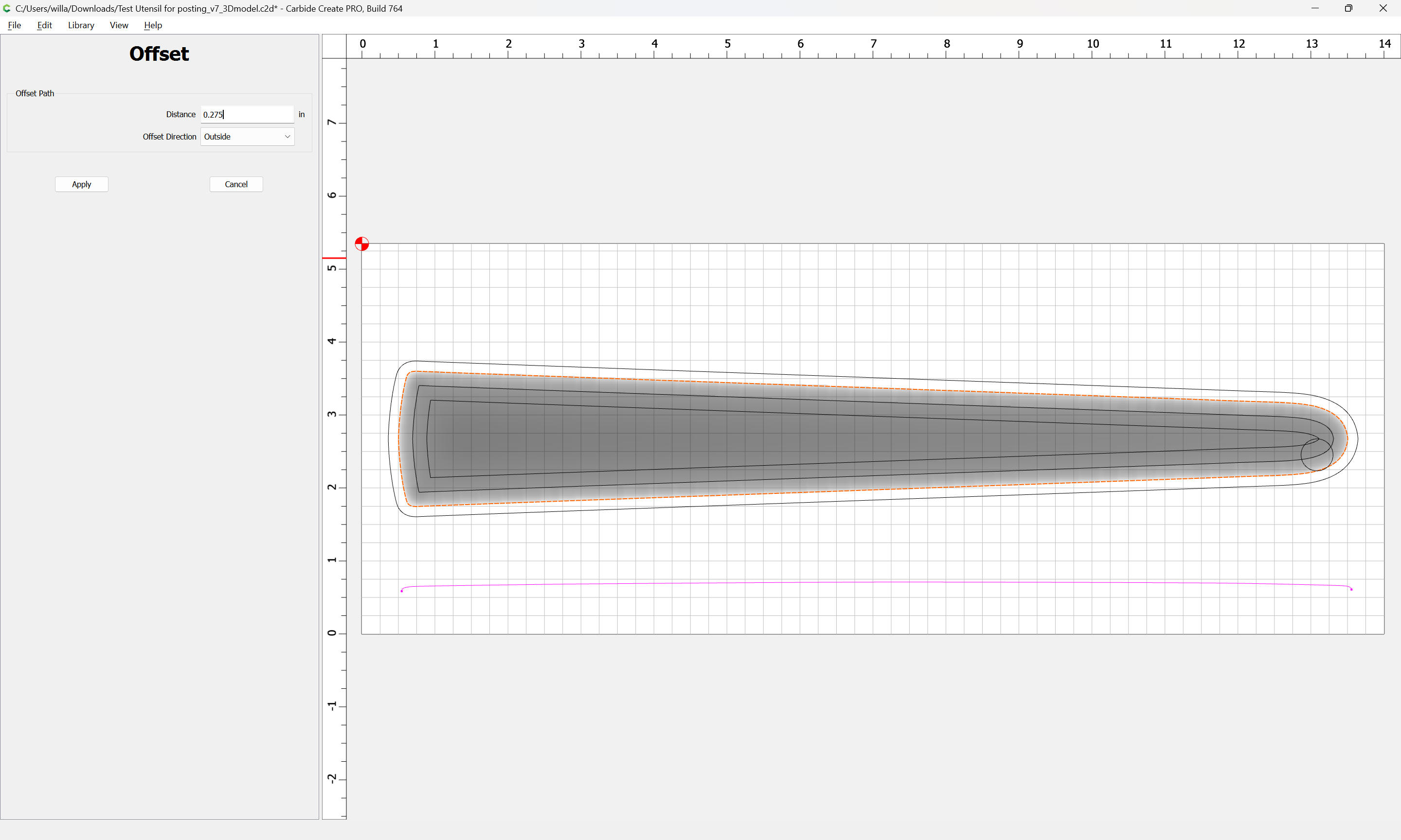
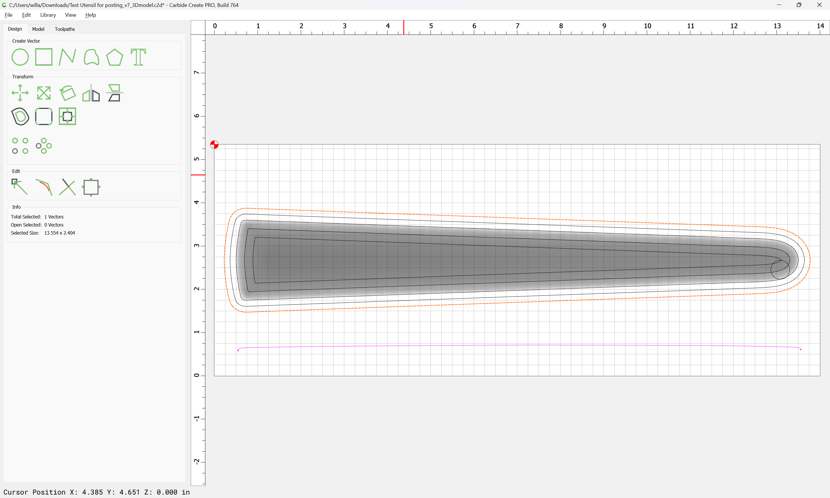
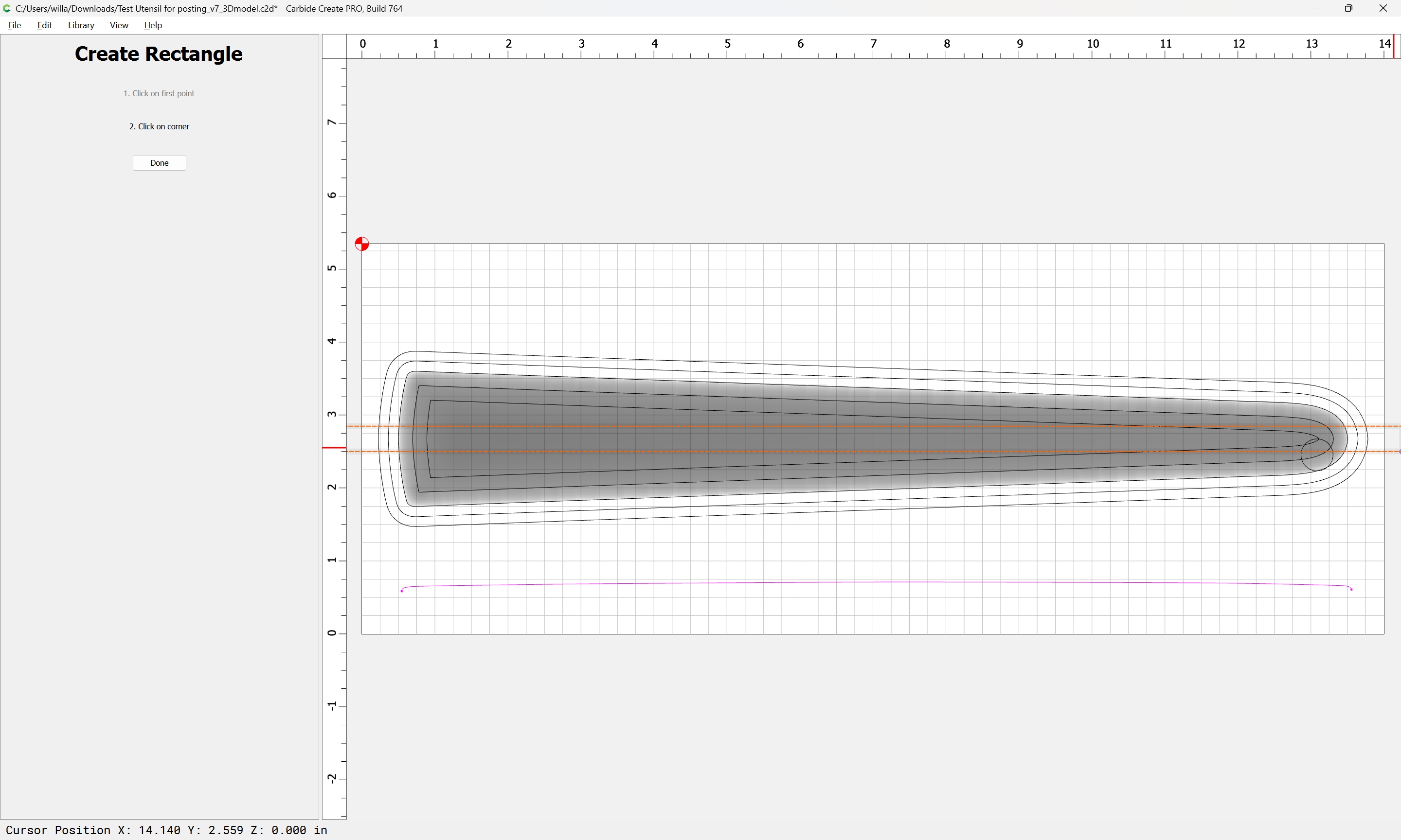
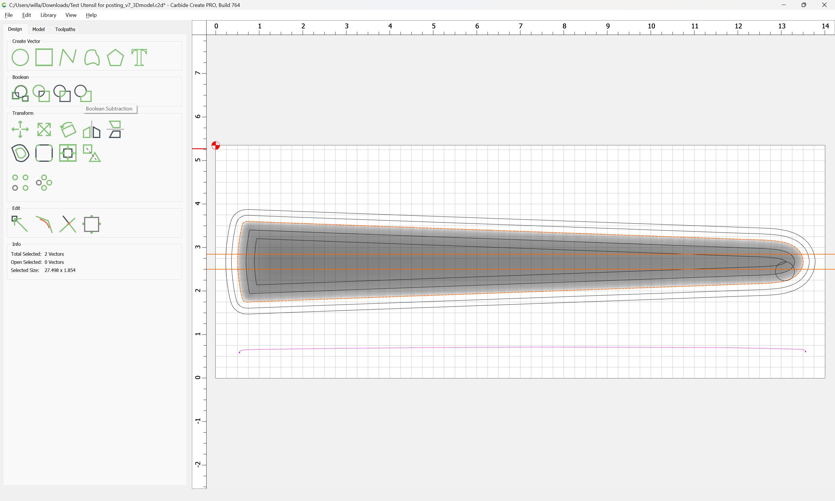
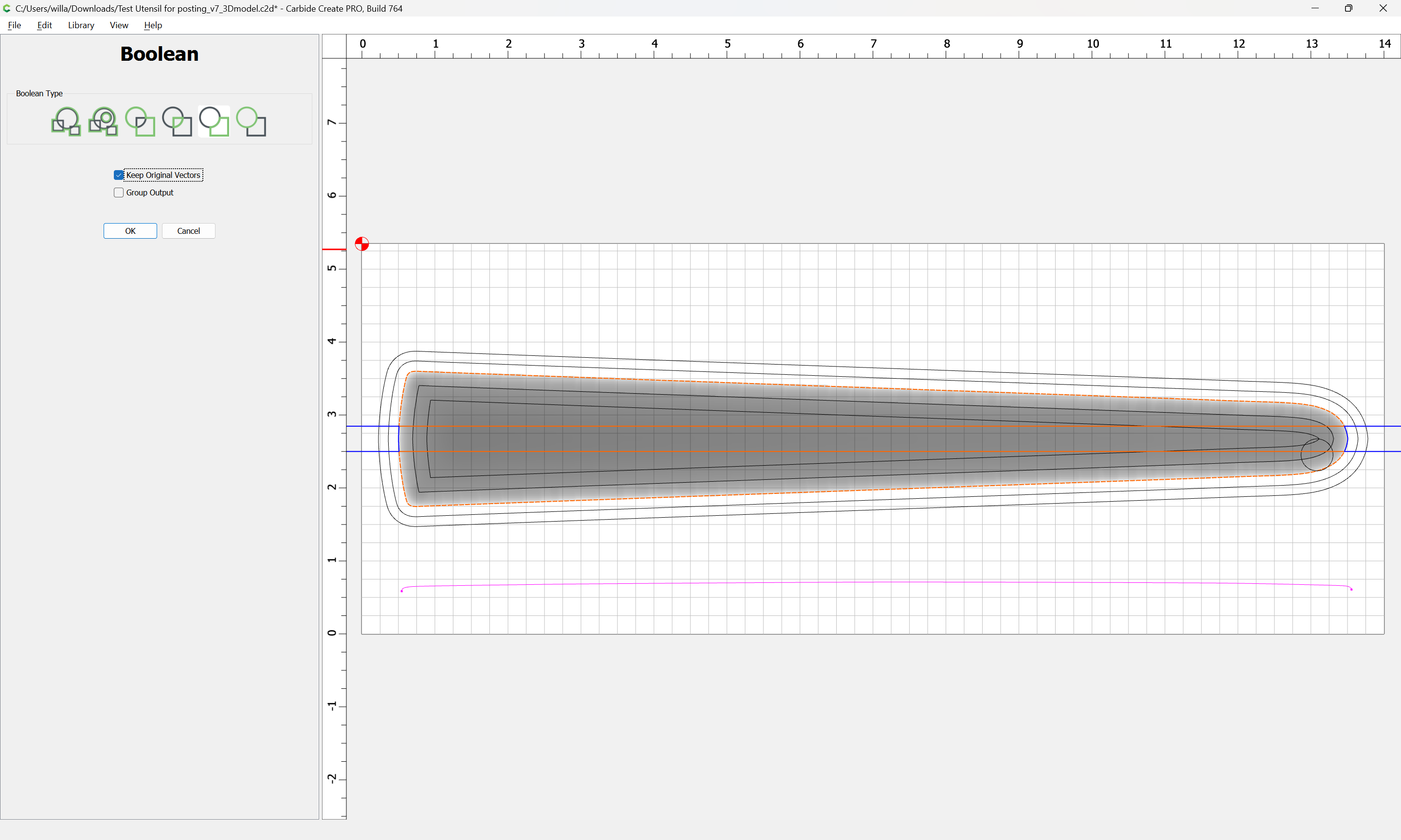
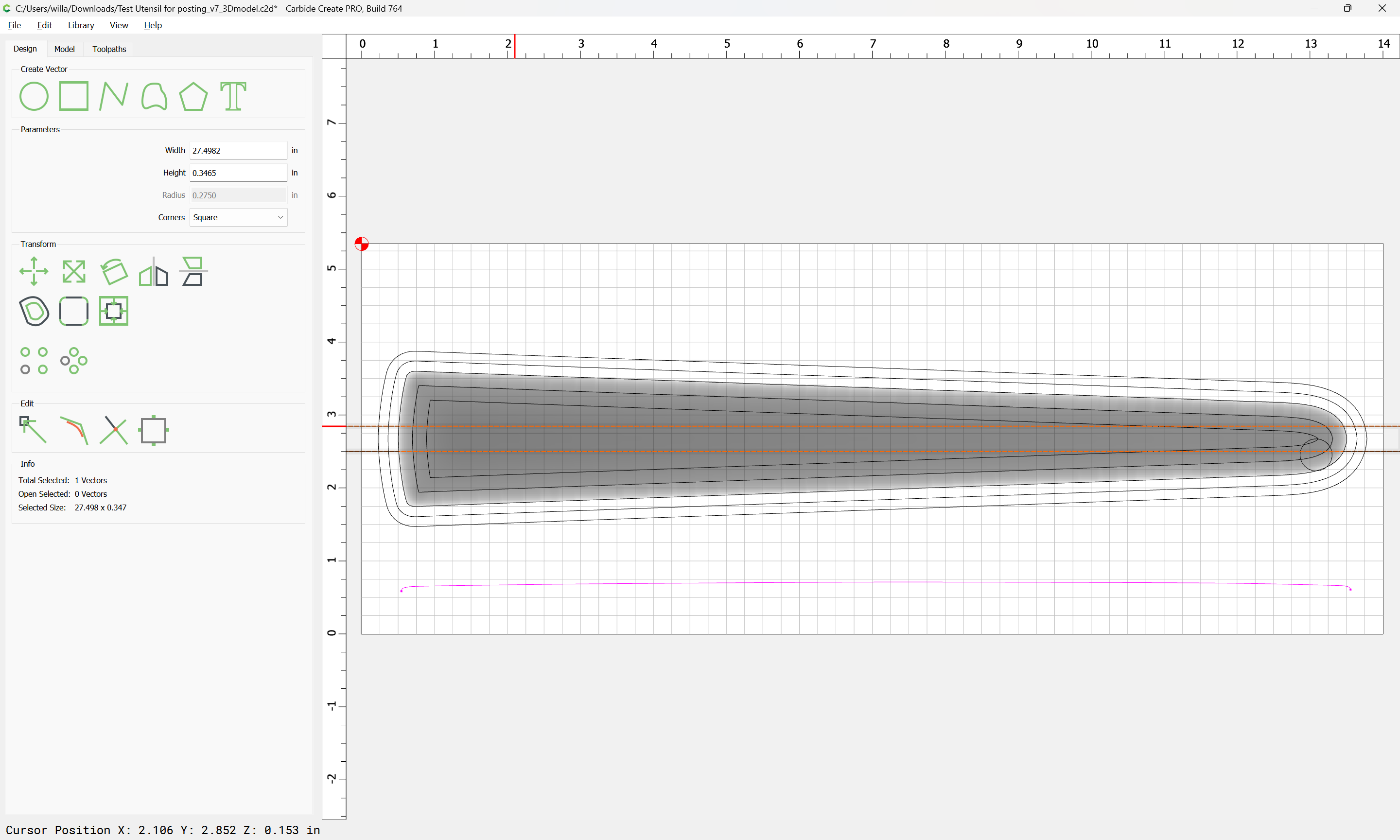
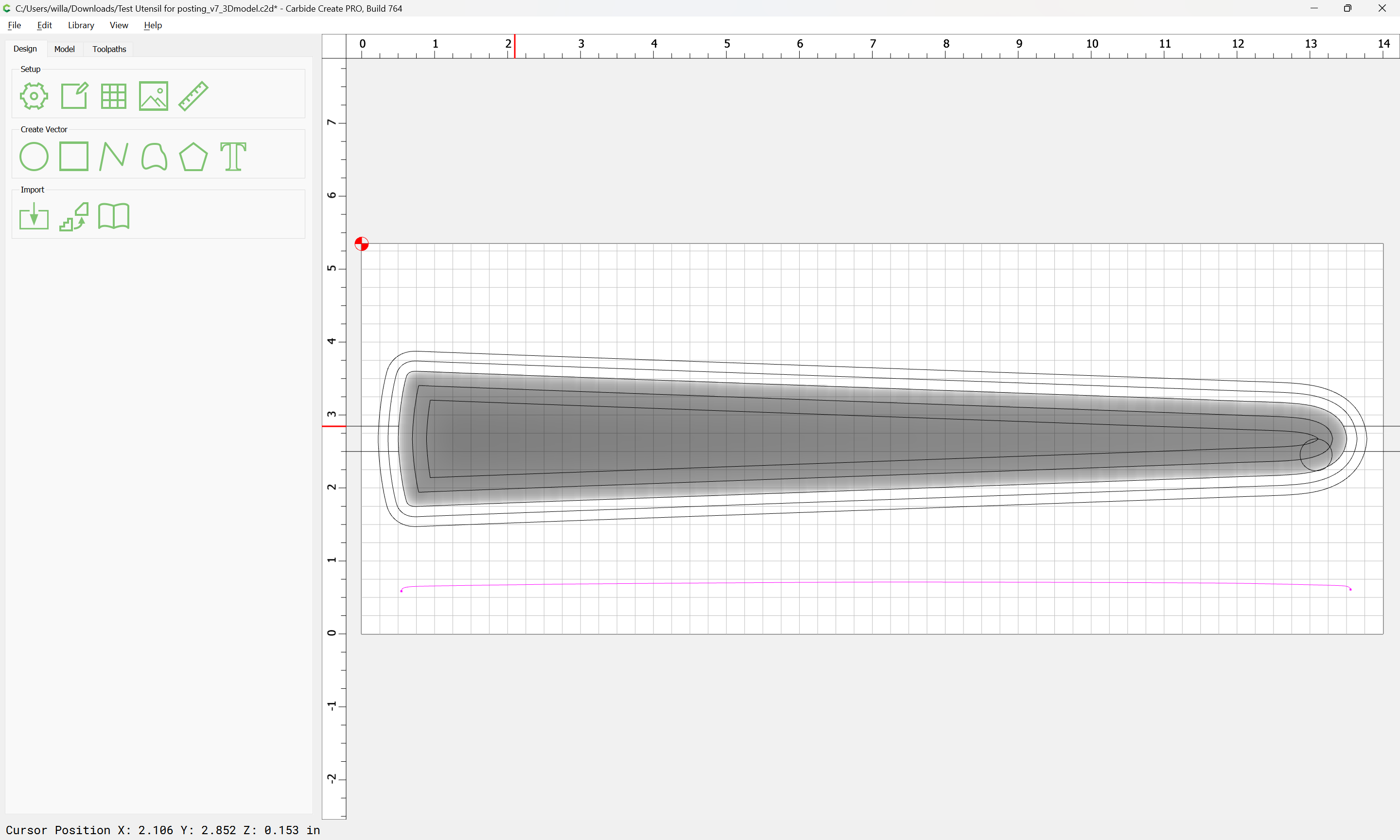
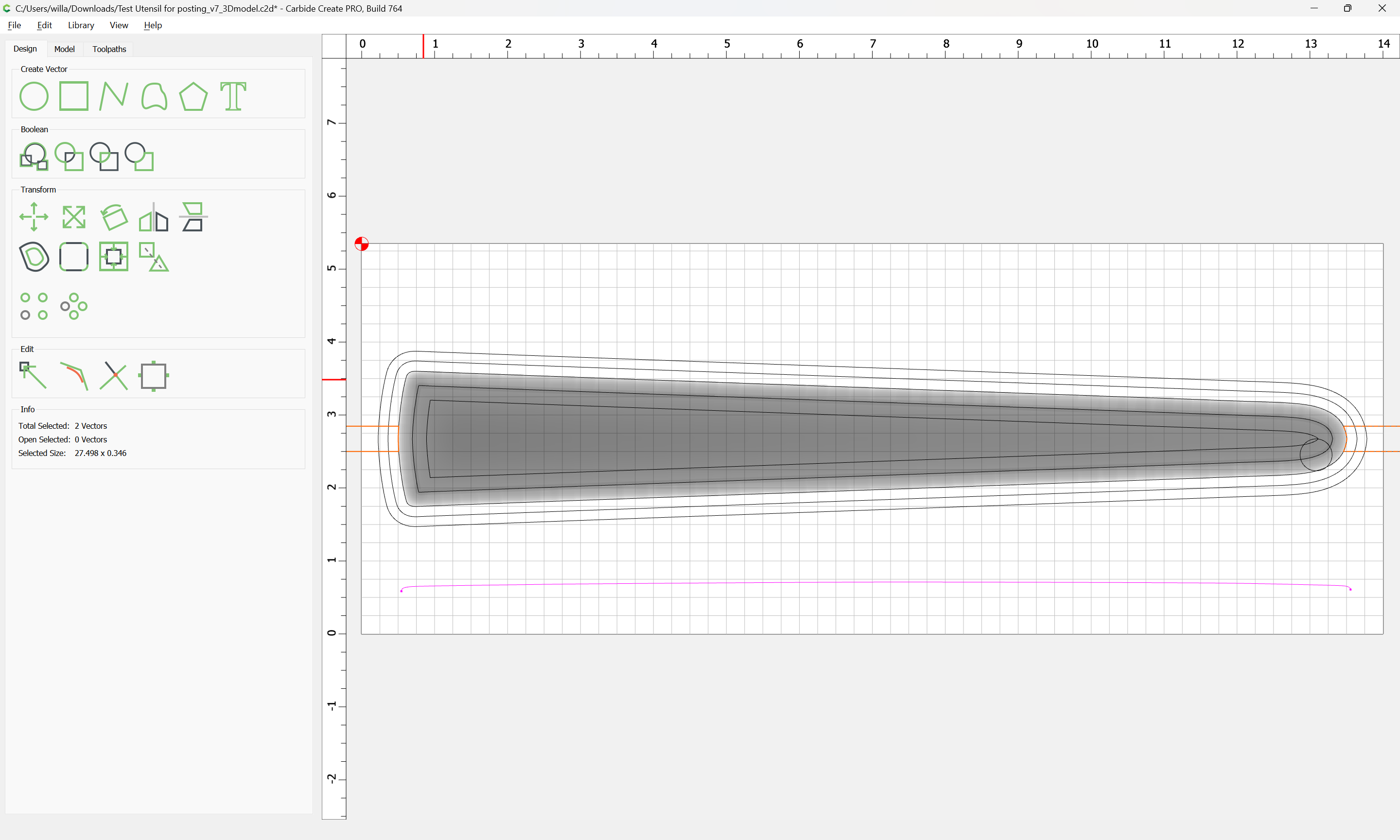
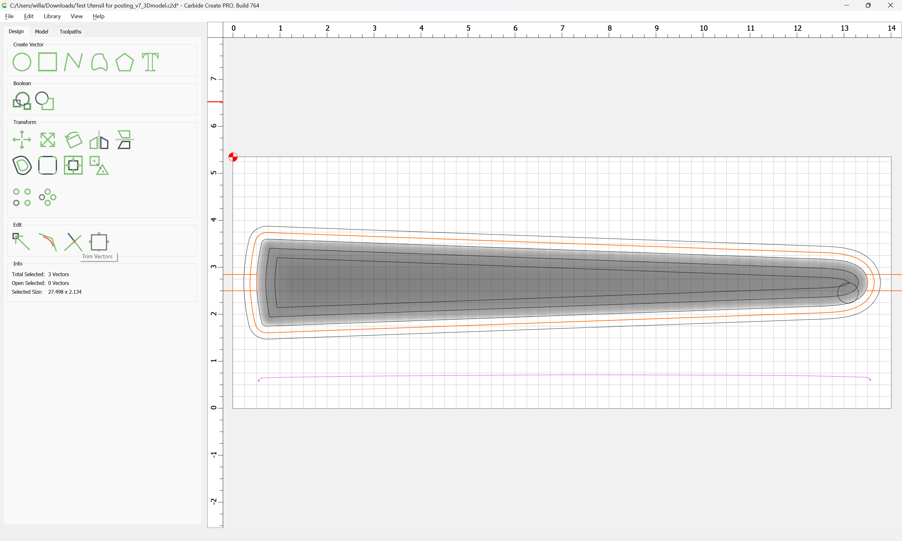
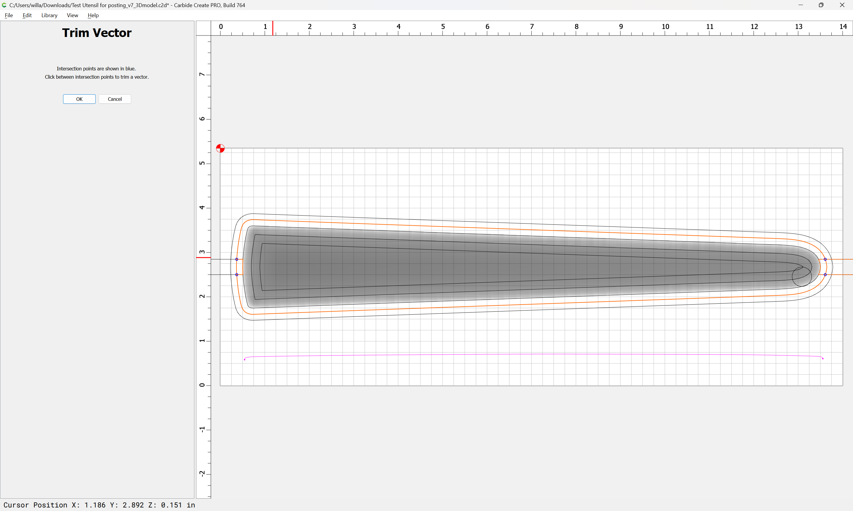
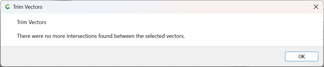
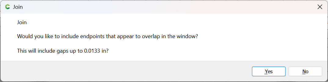
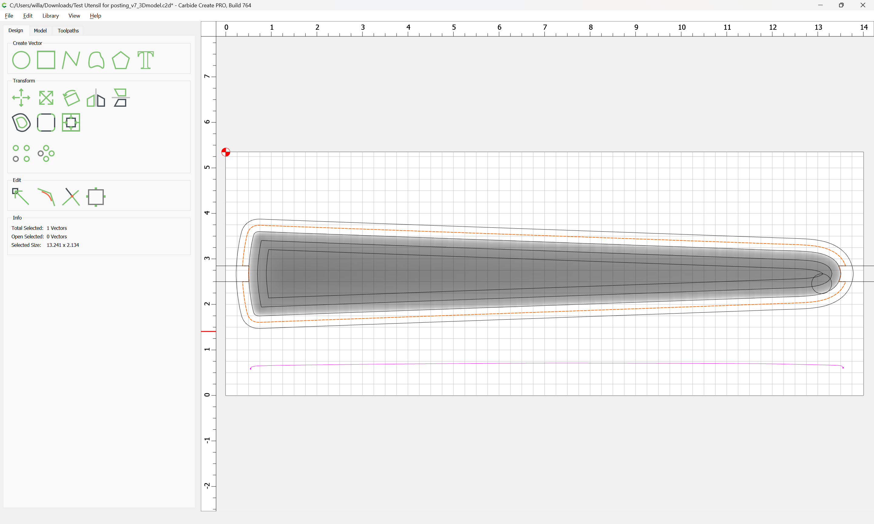
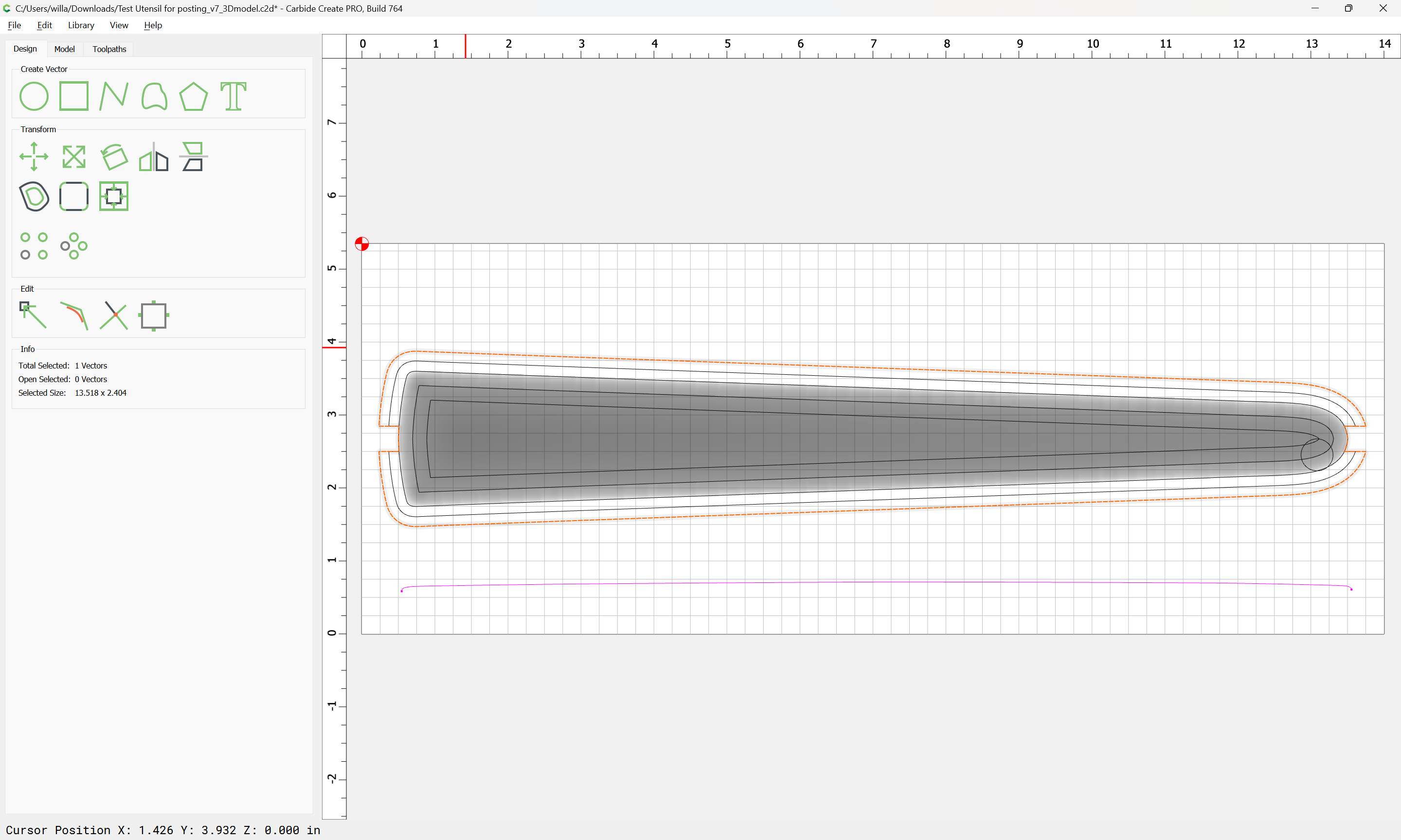
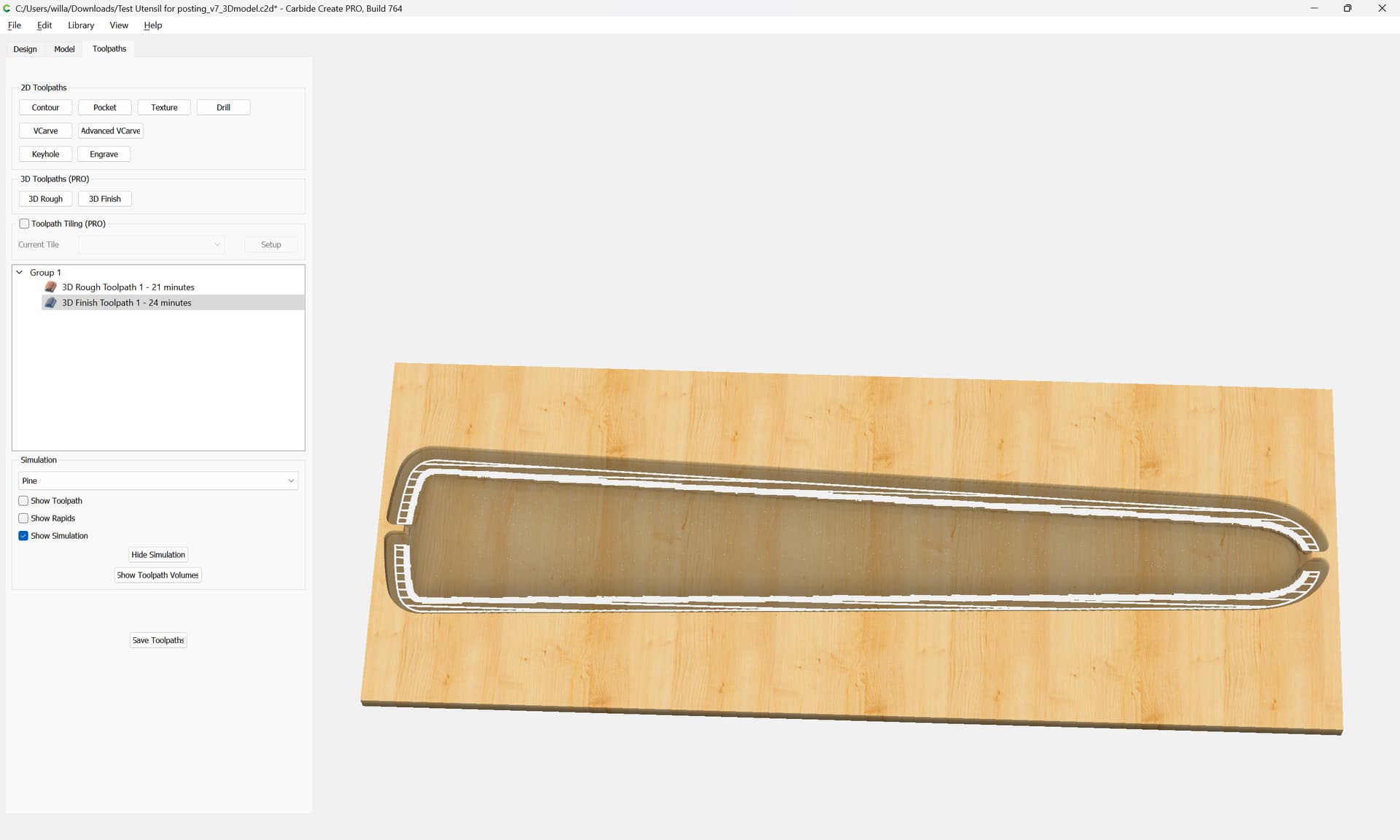
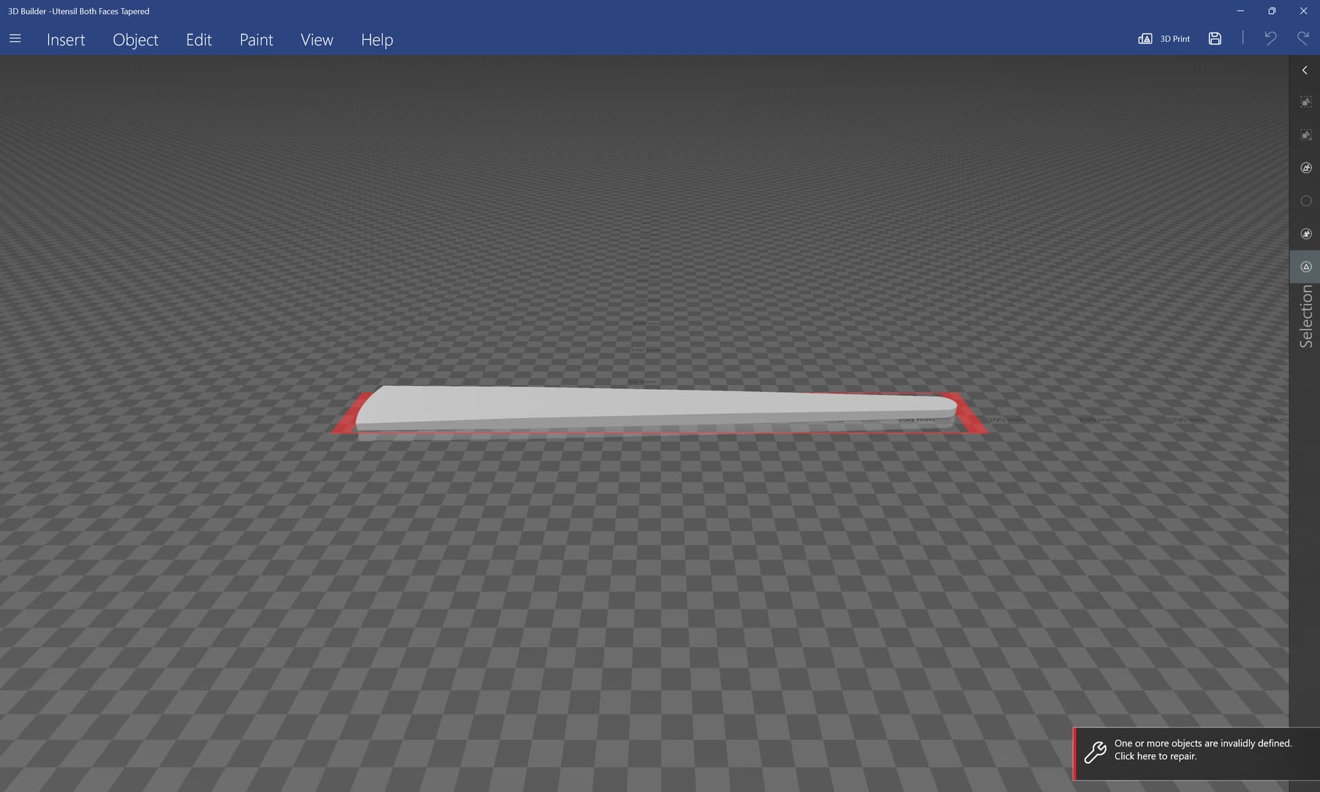
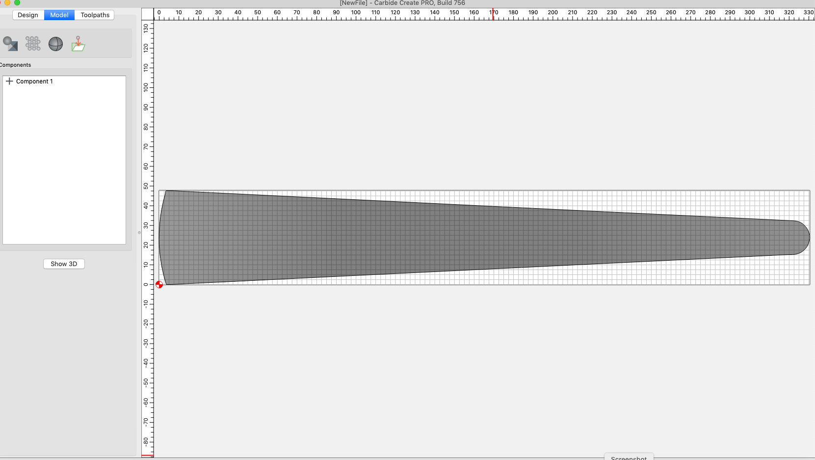
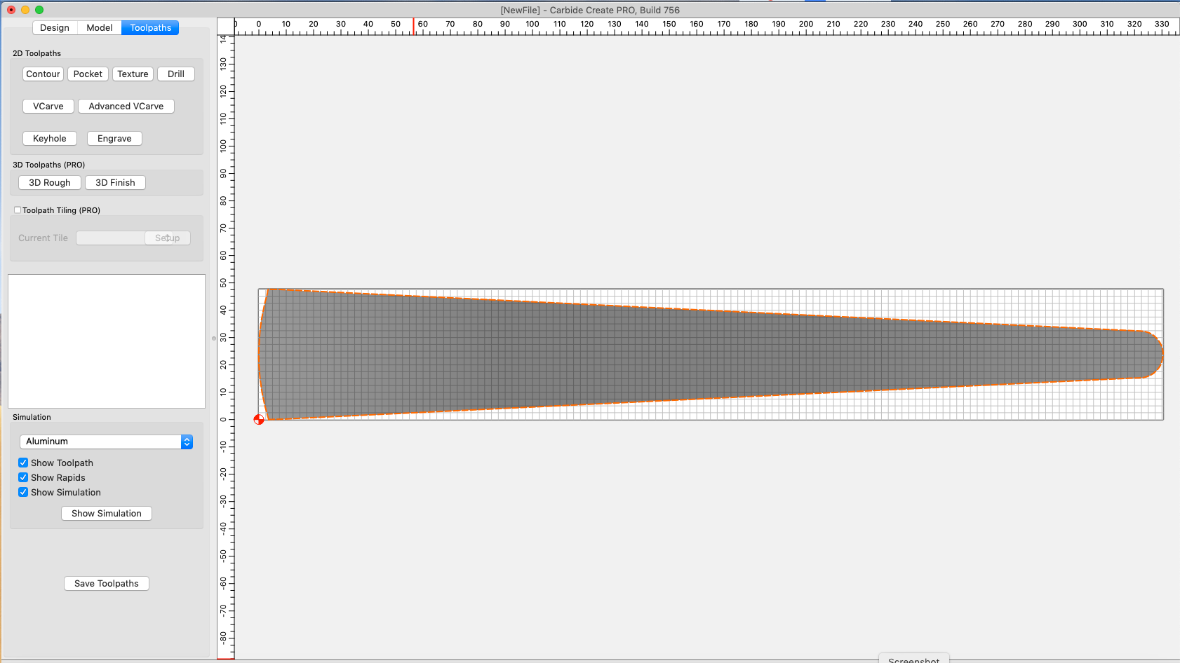
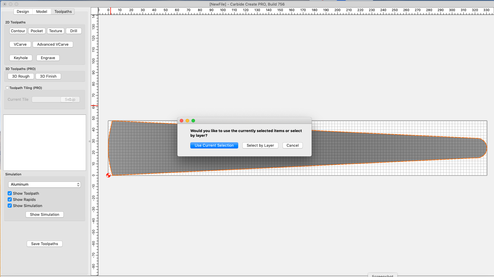
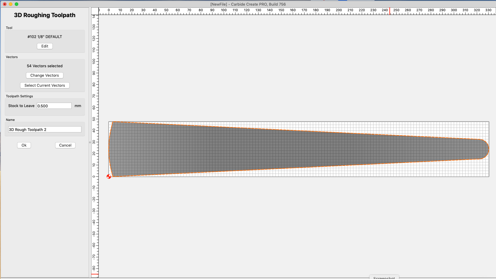
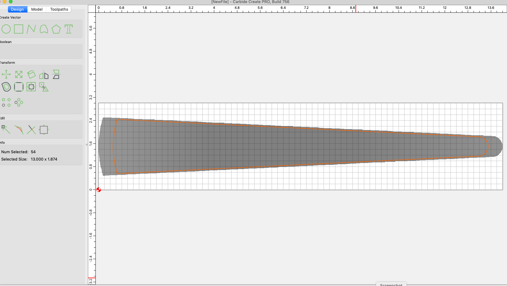
When I go change the stock size, it doesn’t seem to change the model size, just the outline. Not sure how I can machine it like this taking into account clamps and a corner to hold the workpiece. There’s no place for the bit. Same goes for centering it on the stock. I get the following images, which I don’t understand.


I’m hesitant to start machining because I don’t want to destroy my clamps and or corners.

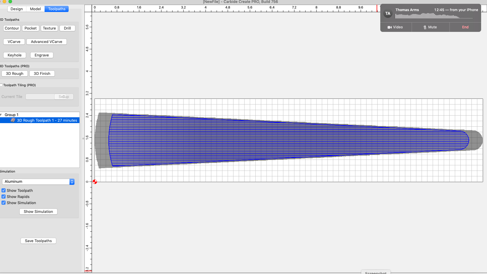
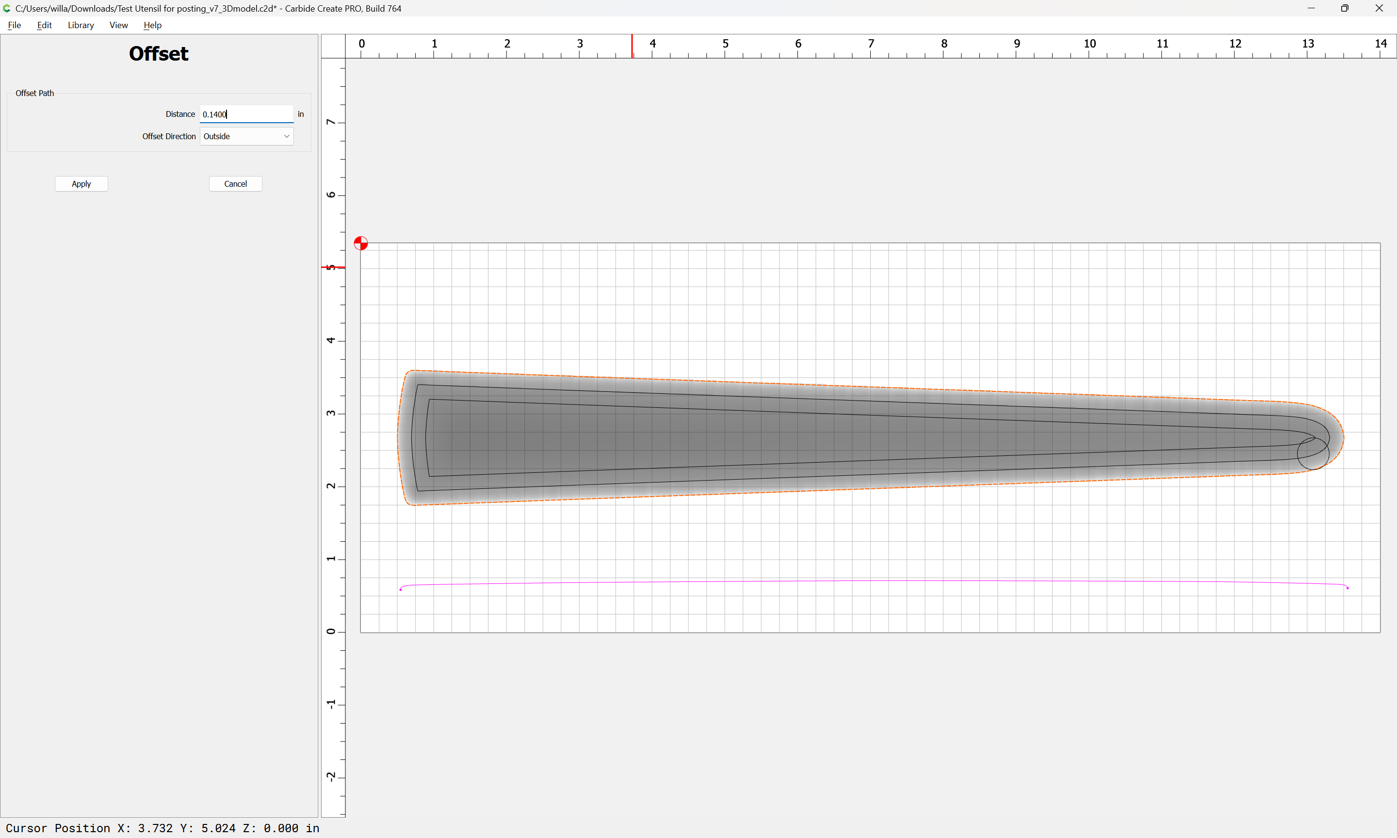
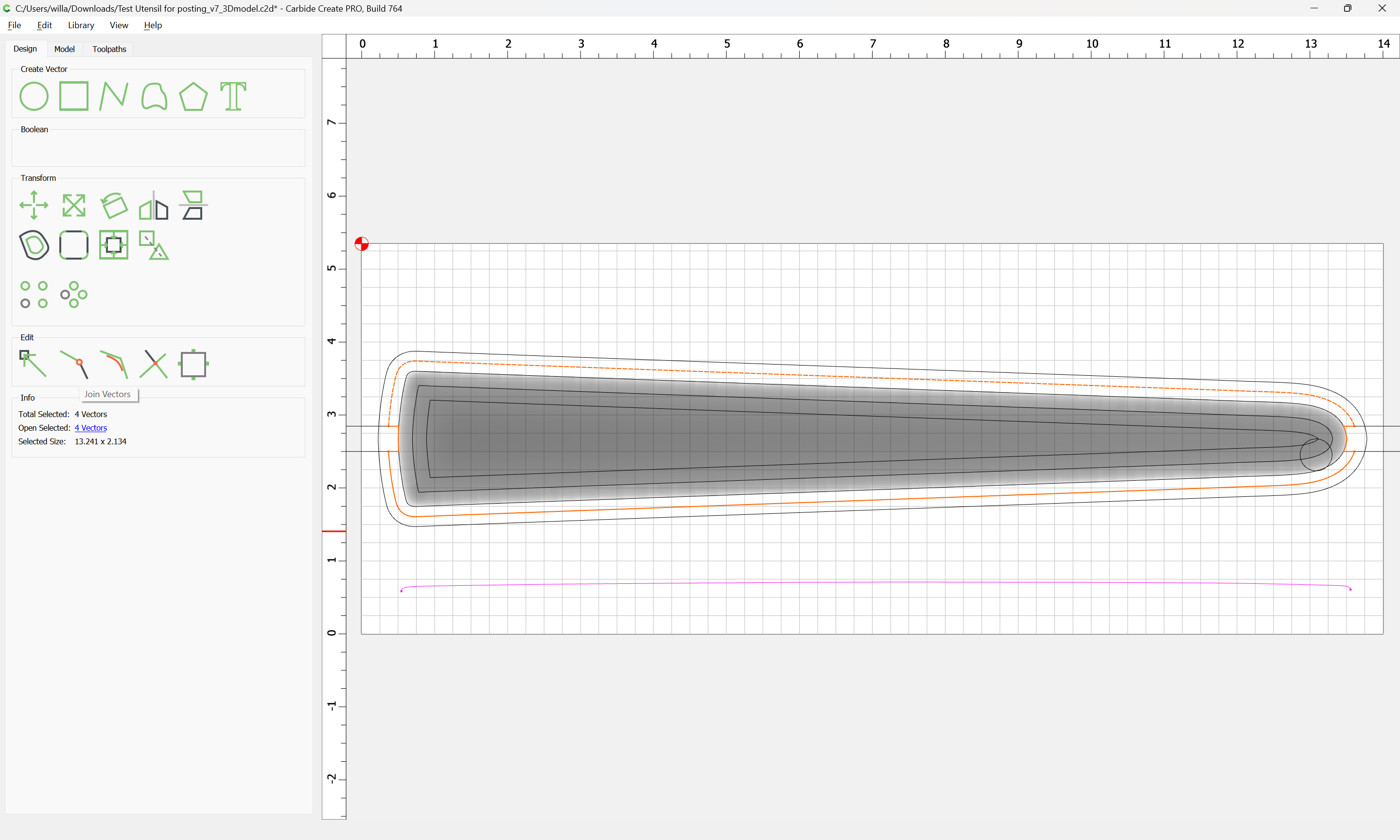
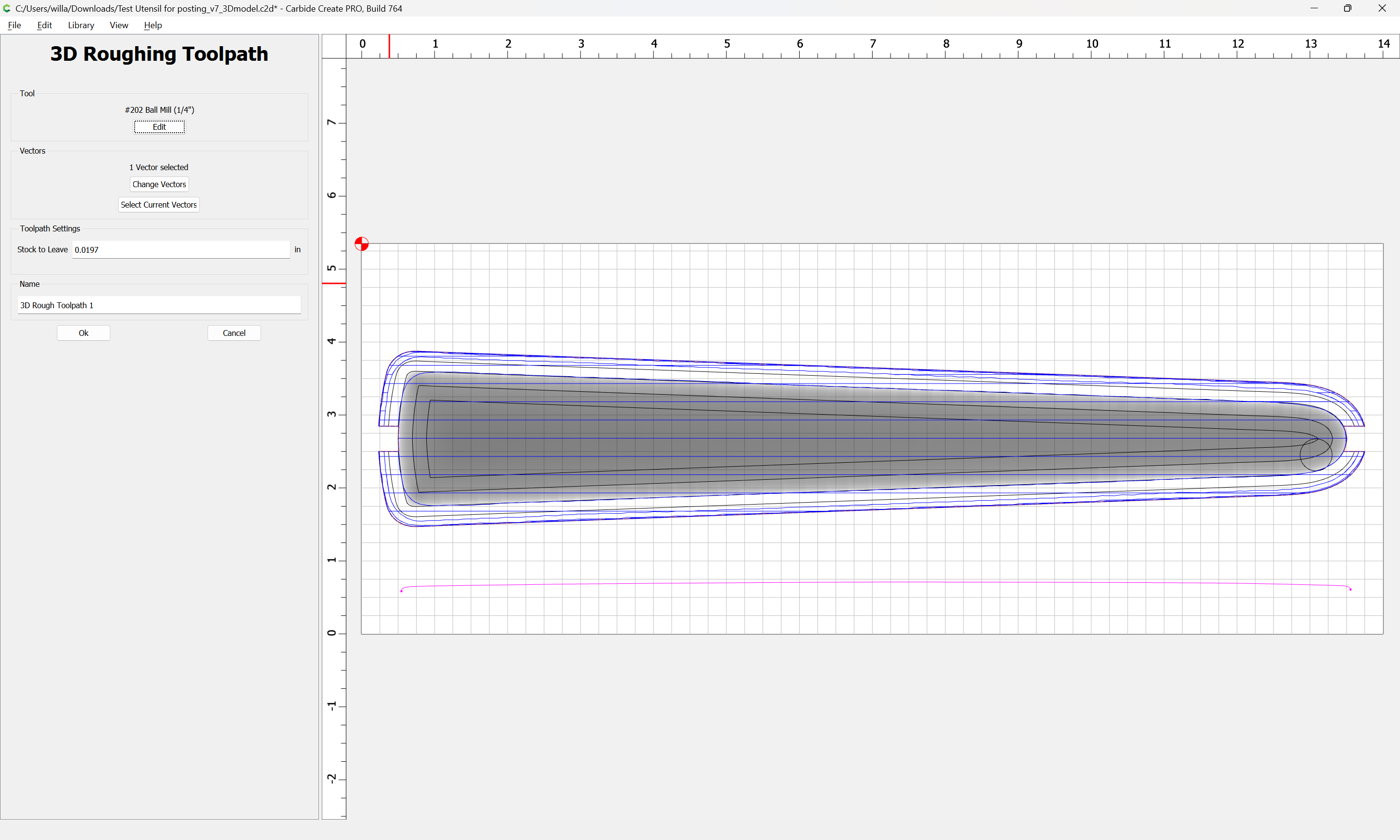
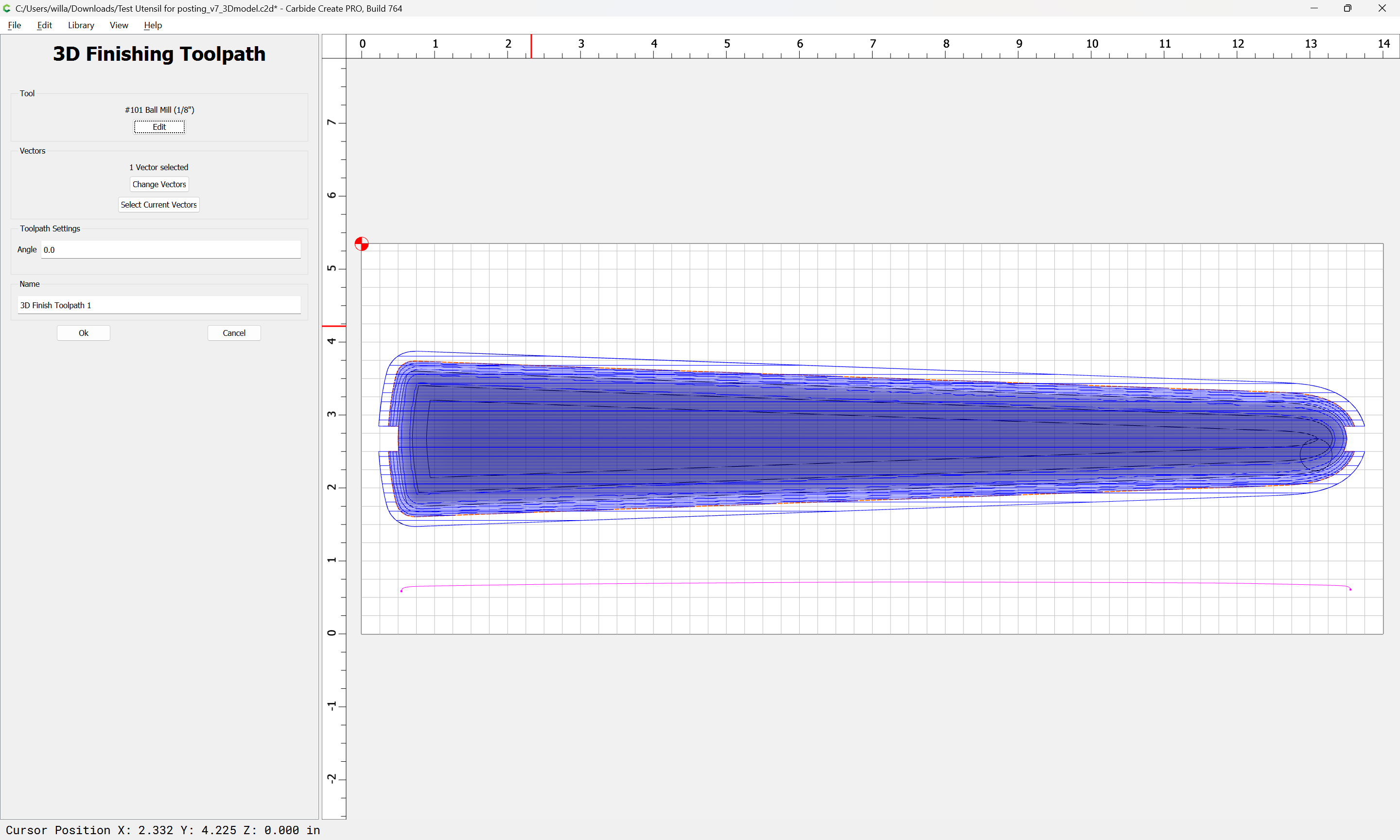
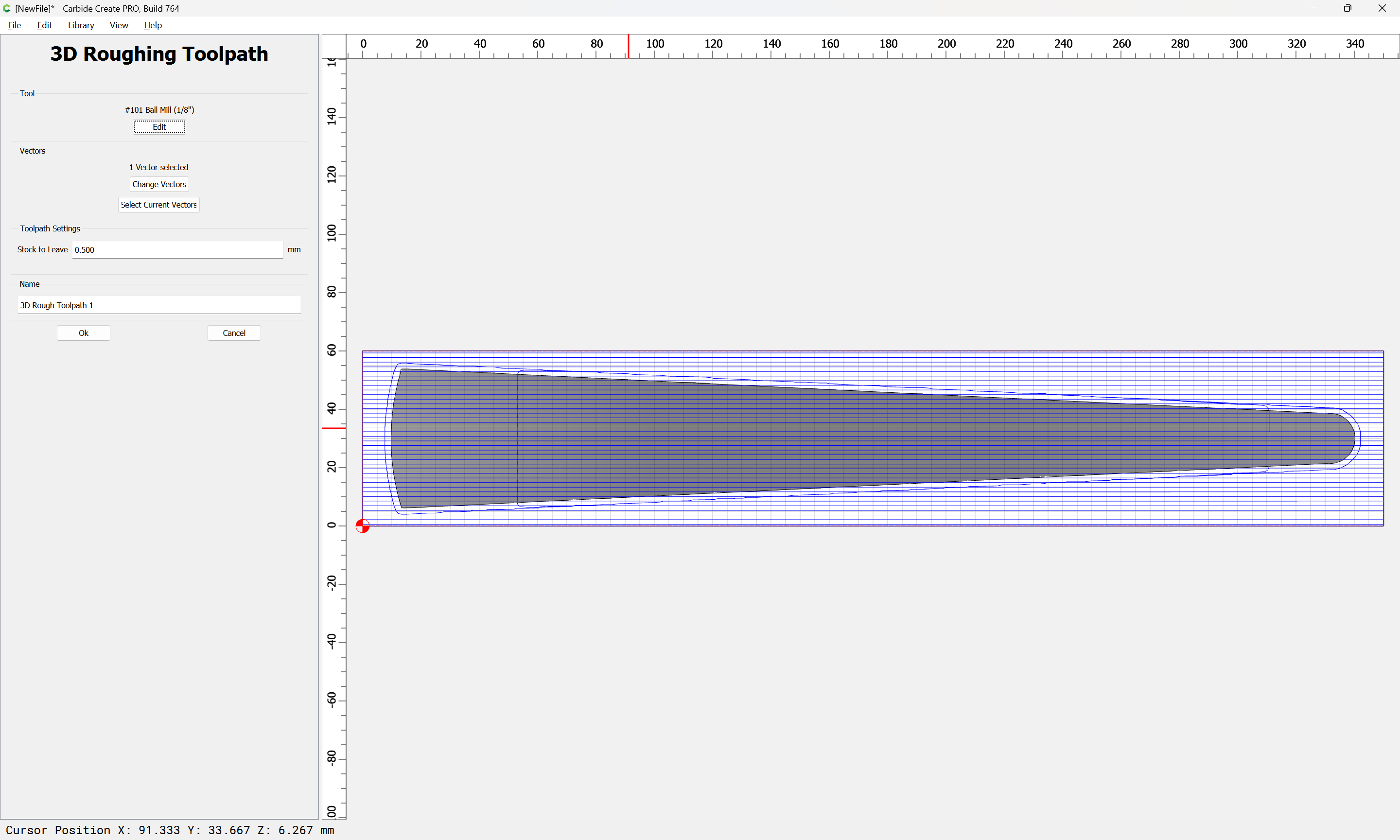
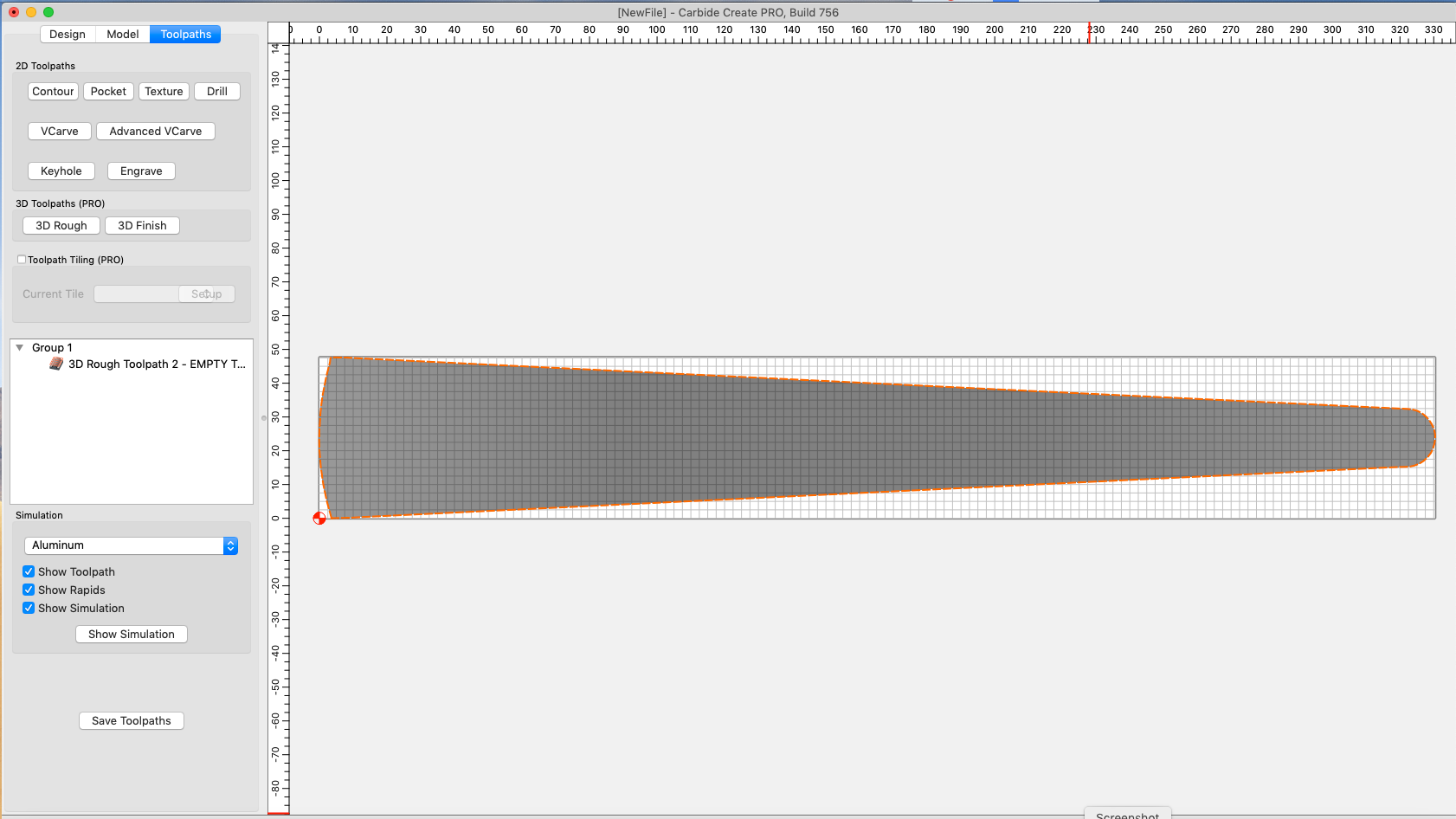
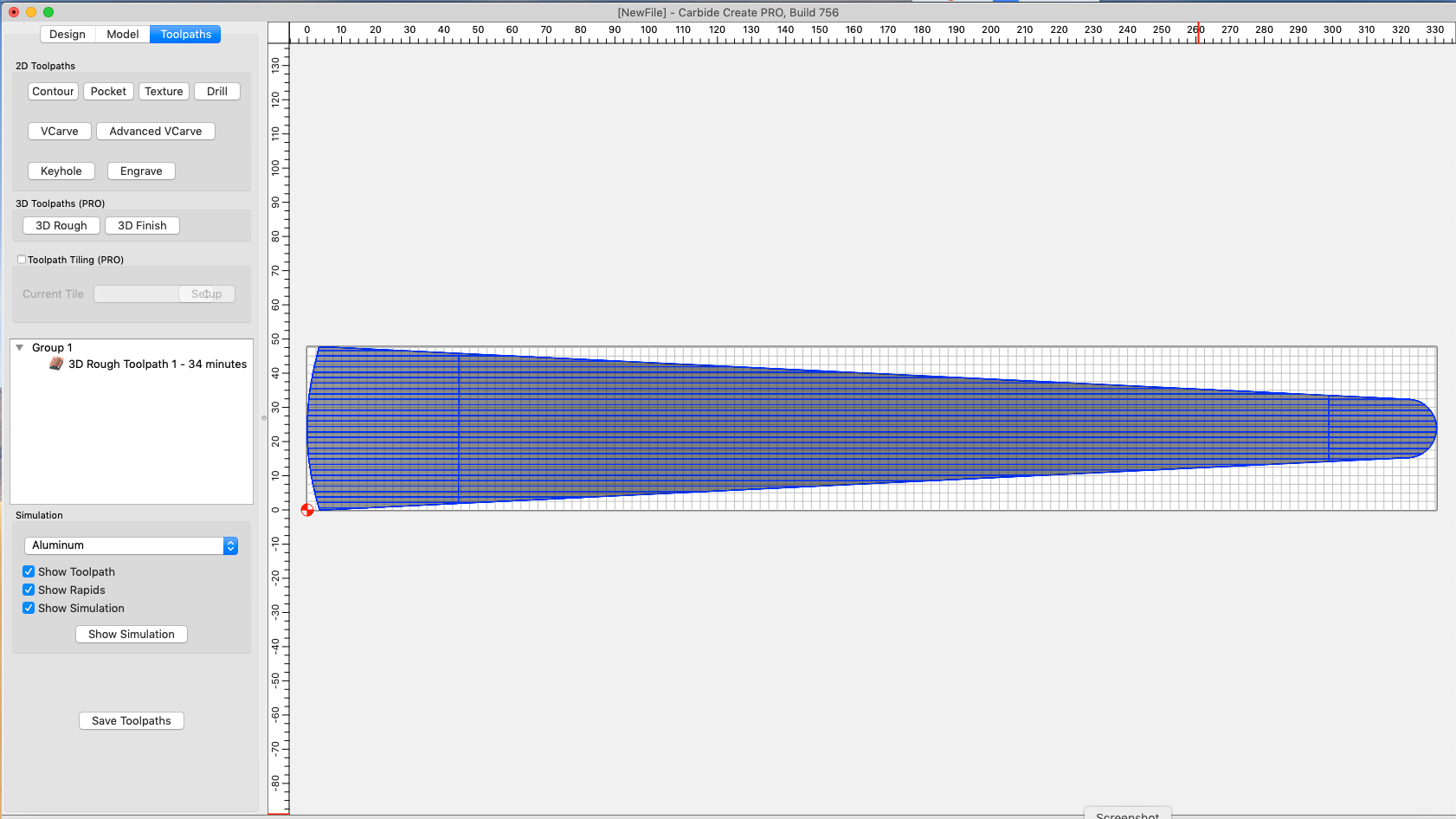
Then here’s what the tool path shows. Which is confusing, also.

First consideration is where the origin will be for the first side, and where it will be for the second.

See:

I consider the Essentials clamps a consumable — buy a spare pack and don’t worry (esp. if you’re w/in your 30-Day “Mistakes are on us” period: For 30 Days, Mistakes are on Us )

The way I would do this is:

Figure out where the centerline of the part is by drawing a rectangle from a node to the corner:

duping it and moving it register with the matching node at the other edge:

Selecting both to get the overall dimension:

and set my Job Setup and Stock to match:

Then cut the first side thus, but for the second (since this is top/bottom symmetrical), re-orient the part by rolling it 180 degrees from front–back and set the origin so that that same corner will be used for origin of the second operation:

For the geometry associated w/ the toolpath, offset to the outside by the radius of the tool you will use for finishing and roughing plus 10%:

(if using a 1/8" for 3D Finishing)

(if using a 1/4" for 3D Roughing)

Draw in geometry along the centerline for a sprue:

ensuring it is aligned w/ the center of the part/stock.

Then remove the part from it using Boolean Subtract (ideally leaving the original part behind):

OK

Delete the original rectangle:

Select the trimmed rectangle and duplicate it:

subtract each from the offset geometry, either using multiple Boolean operations or (easiest) Trim Vectors which are then joined back together:

Remove what is not wanted:

Ok

OK

Join Vectors

Yes

Repeat for the other, arriving at:

Select the outer geometry for roughing:

and the other for finishing:

(adjusting the stepover as desired for finish)

Hi Will,

You’re going to hate me, but I don’t understand anything you’ve described above. I thought once I had an STL model, I could just machine it, once on each side, as described in the two sided milling video. What are all these other steps for? I am completely lost.

And before we dive into the above, I still have a basic question:
Why does CCP change the size of my part? How can I even begin to make the part when CCP changes the size upon import? I’ve watched the STL video by Kevin and I don’t see any of this mentioned when milling from an STL. I’m so sorry to keep bugging you, but I am at a total loss on how to get this object milled.

Sorry!

The extra steps are necessary so as to have a “sprue” for the two-sided machining operation — probably they could be added to the 3D model easier.

Carbide Create Pro has 3D modeling like to that in Vectric Aspire which seems to be best suited for decorative use.

If you want something to come in at a given size you will need:

  • to know what that size is — check the STL using a 3rd party tool such as Microsoft 3D Viewer
  • have the STL saved in a file format which accurately captures that size
  • import into Carbide Create Pro at scaling 1.0
  • set the Height on import to match the height of the model

See:

I suspect you’d find MeshCAM a bit more workable for this:

Reading that Tutorial I see that they took an STL file and just cut it out. It looks like a simple 2D shape. I see that they added the bit diameter plus 10%, but I don’t understand why. Why do that step when I can just have CCP do a contour cut around the outside of the current object?
And what does a sprue actually do? I watched that video again and don’t see any mention of it.

I’m totally lost. If I go in and scale the STL to the size I would like (which is exactly the size I’ve created it in VWX) then try to do a 3D roughing toolpath, I just get an “EMPTY TOOLPATH” message. If I leave at the in correct size (scaled up by 1.076, that the program chooses) and then go to try a rough tool path, it works. I have no idea what I am doing wrong.
Here’s how it comes in:


For some reason, if I do any scaling at all in CCP, I get an empty toolpath. It seems that regardless of the model size, CCP scales it to the stock size and then any changes past that result in an empty toolpath.
Here’s the STL if you want to give a try. In VWX the LOA is 13"
Utensil Both Faces Tapered.stl (10.8 KB)

The extra geometry and space around the part is to allow cutting out without burying the tool in a slot.

A sprue is an attachment point which keeps a part in place, whether in molding or for a 2-sided operation.

When I open that file it has to be repaired:

Once it is repaired, I get dimensions of:

Importing that we get:

We change XY Scale to 1.0 and Height to 6.4 and Apply:

We then select the outer geometry and cut a 3D Roughing toolpath:

then a 3D Finishing toolpath with a very fine stepover:

to arrive at:

Hmm. Something is very odd here. My STL imports just fine into CC. But just to follow along, I’ve set my stock size to match what you found.


Importing the file give me this:

Now I’ll change the height to 6.4

and hit APPLY

Now I’ll hit DONE.

Now on to Toolpath and select object

Use Current Selection

Now 3D roughing menu

After hitting OK I get an empty toolpath.

I think I am following your steps, but it seems anytime I scale or change anything , I get this empty toolpath. Is there a step I am missing?

You didn’t change the scale to 1.0 and you’re not selecting geometry larger than the model to associate with the toolpath and you’re not choosing a tool other than #102 DEFAULT.

See attached.

STL_import.c2d (1.1 MB)

Note that you can click on the screen grabs here to see them at full size on your screen — that should make it easier.

Maybe @KevBarn14 can do a video you can follow along on?

EDIT: a further concern is that in the above file, the part is cut all the way through from the top — no sprue — it would be better to model as before, adding half the thickness.

Hi Will,

I hope this thread doesn’t kill you! :slight_smile:
I am having a really hard time with this whole thing. This seems to be the simplest thing. People are making height maps of mountain ranges. I just want to shave off a little bit of wood on an angle. Here’s what it looks like in 3D.


If I just open the STL file without doing anything to it (knowing its height is scaled incorrectly) and choose a roughing toolpath with a 1/8th bit, I get a time of 34 minutes. Is this not really a toolpath?


If I add a finishing toolpath, that adds another 13 minutes.

Even this seems like a really long time. I’m basically taking away an 1/16th inch of stock on only 2 portions of an object that is 2" wide. It’s just cutting a slight angle. This seems like a long time to me.

If I then do ANY scaling to the file (such as changing the Z height) I can no longer generate ANY toolpath. I don’t understand this at all. What changes? Also, what does “Stock to leave” mean?

And looking at your file, the machine time is like 240 minutes total (and this is just one side). I must be missing some very basic concepts here and I feel like an idiot.

The 3D model has to be set to the right size at its creation.

If should be okay to scale the geometry which defines the toolpath after.

My file had the stopover for the 3D Finishing toolpath set very high.

I suspect you’ll find MeshCAM more workable.

When you say “The 3D model has to be set to the right size at its creation.”, what do you mean?

When it is imported into Carbide Create Pro, that’s when the size is set — if that isn’t what you want, you have to delete the model and try again.

So if the model is the correct height, why does CCP change it to a random height?

The default height when importing an STL is 3mm

Ah, OK. But why then when I change just the height, am I unable to make the same toolpath?

Please post two files which match save for the height and we will look into that.

This topic was automatically closed after 30 days. New replies are no longer allowed.