First time user of the McFly Surface cutter; using the 602E 1/4" bit.
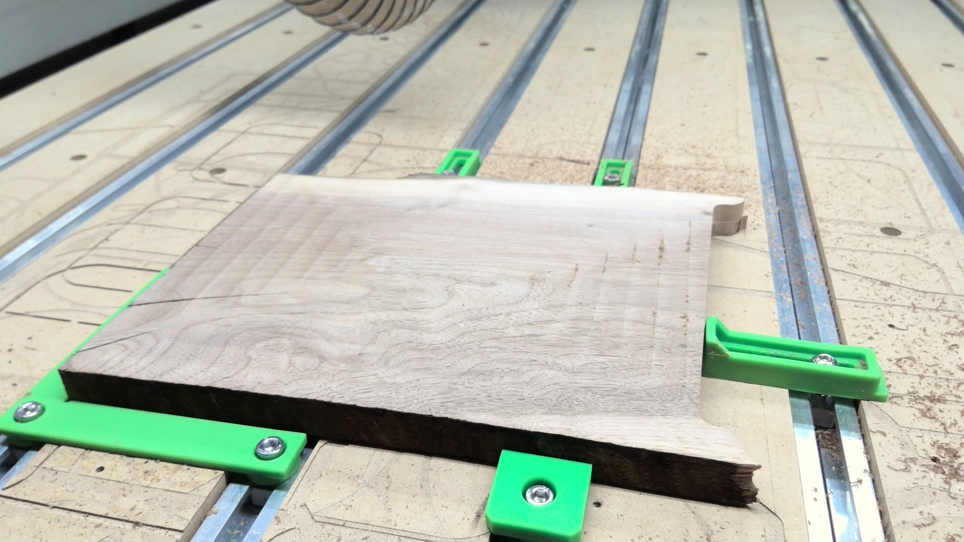
I have a small piece of walnut that I wanted to take down to a flush surface. I found in my first mill the bit is leaving a little ridge as if the cutters on the bit are not level. It is especially noticeable on the cross grain cuts of the wood. The cuts along grain also have a very small grove, but it is barely noticeable.
I know the back of the wood is also not smooth yet, and I believe I can get this smooth with a sander, but would like to get this right for when the project really counts.
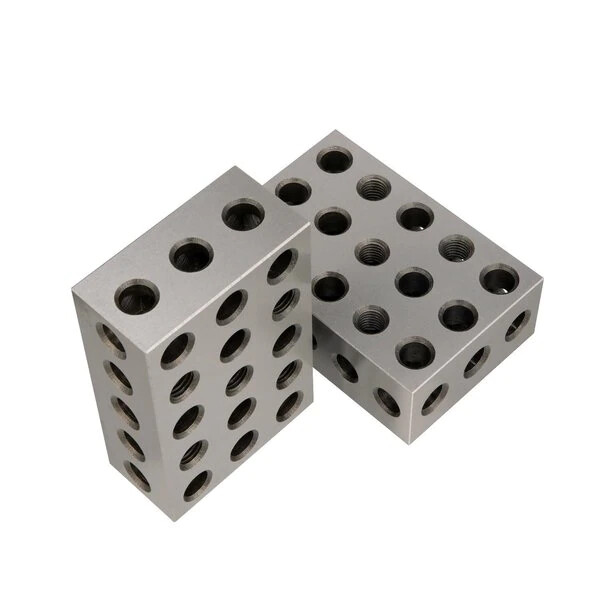
The blades of the McFly cold be out of alignment but not likely. As @Etch8SonsCustoms suggested it is likely your router is not square to the spoilboard. There are several ways to fix this problem. The cheapest and easiest way is to remove the router and buy some 1 2 3 setup blocks. Lower the router down on the 1 2 3 setup blocks and adjust the eccentric screws on the router mount until the mount touches both sides of the blocks. Then jog up and turn the 1 2 3 blocks 90 degrees and see if the mount is square front to back. The adjustment of front to back is not hard but requires you to make shims out of aluminum foil or maybe cut up a soft drink alum can. You loosen the mount and put the shims at the top or bottom depending on which way the mount is tilted. If it is low in the front and high in the back then the shims need to go at the bottom of the mount. If the router mount is high in the front and low in the back then shim the top of the mount. After recheck the left to right again with the 1 2 3 setup blocks. There are a lot of places to get those set up blocks and Amazon has plenty at a cheap price.
All above suggestions are great and spot on. Start at the base of your machine and work your way up to the router. Be sure your base is solid, level and in full contact with the floor. (not rocking) Then do the same with you machine base. Any twist to the bed of the machine will give similar results of what you see in the picture. The bigger the cutter, the more pronounced it will be.
Thank you everyone that has responded on this thread. I have only had this machine running for about 3-4 months now and am still an infant to CNC experience. But I love it and wish I have done this years ago.
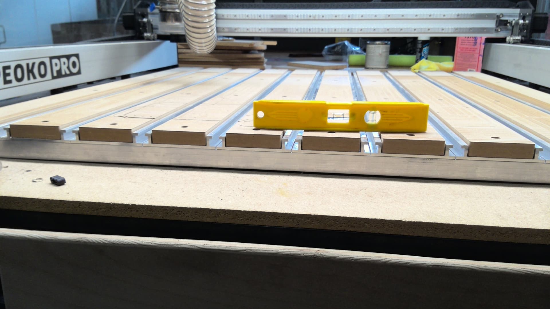
I have squared the z-axis and compared at a few different areas on the spoilboard with some 123 blocks. I also used a digital level and found I was really only 0.1 degree off. Then I cut the spoilboard down 0.25 mm. I found the same issue of groves on the spoilboard which seemed to get worse and worse the further from center it got especially + x and +y.
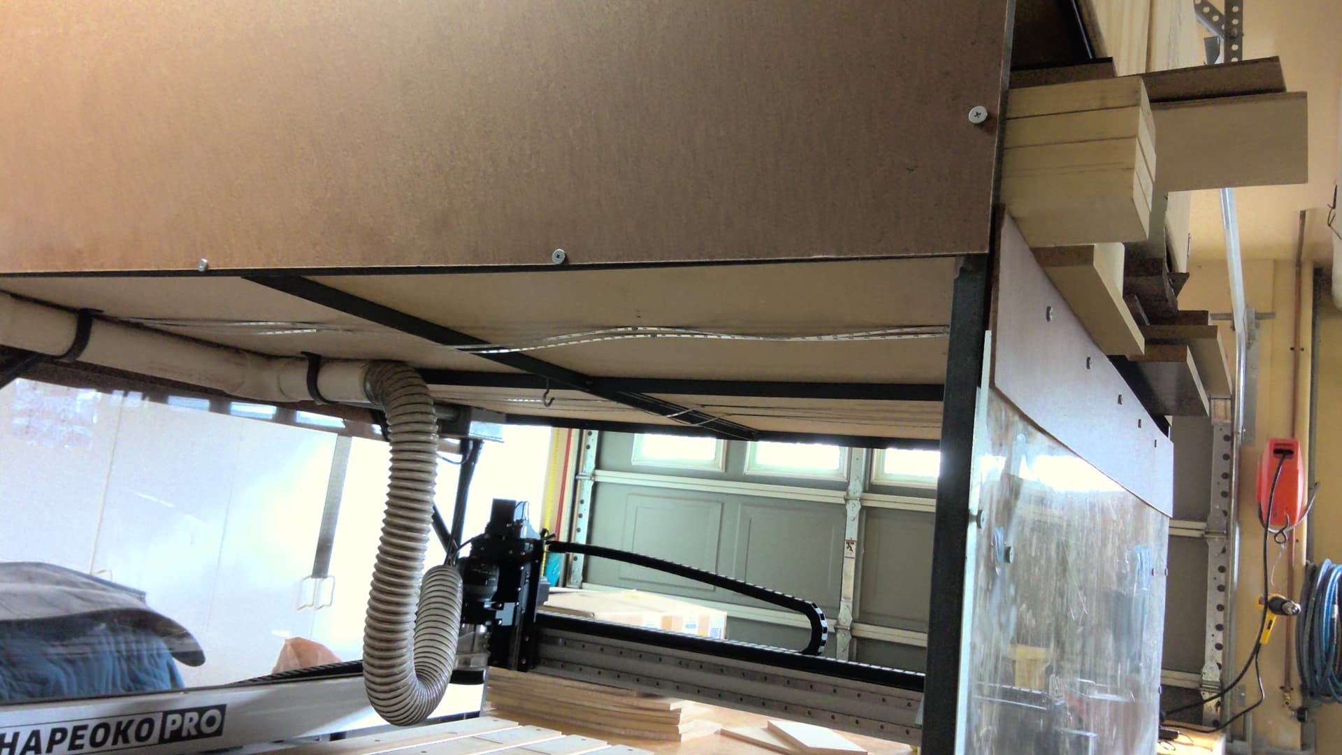
I got a level out and found that x axis is level appears good, but the y axis is not. Then it dawned on me that my garage has a slope and that should not matter. Upon further investigation, I found that my cabinet dips in the center. I used 3/4" angle iron and 5/8" particle board (cost and space saving measures). Unfortunately, this means that the cabinet has some flex in the center of shelves. I am unable to add a support under the shelf that holds the CNC because I was so smart to add drawers all the way around that are basically as large as can be . But the CNC itself seems to have a solid base and doesn’t flex, so I am not sure how important that is since all my projects are relatively small and light in weight.
I am not sure if my cabinet is the cause of this or if I need to go back to adjusting the gantry and z axis. I dont even know where to begin with the McFly to check it, although I do not think that is the issue.
If anyone is aware of good videos or threads that show how to square the cnc, it would be greatly appreciated as I am still combing through the internet and trying to understand it all more.
If you are concerned about the center sagging which I have not seen on mine, you can get pink foam to place under the table. Plus it will help on noise reduction.
The distance from the spoil board to the router should be consistent to with in the parameters we want. If you are still getting ridges, check your tram at multiple places on the table.
Etch,
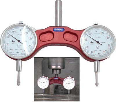
Watch this video. You do not have tools tram your head this way nor is your machine a manual mill but the concept is is the same and if you use your imagination and I think you will get it close. Having your machine level and solid is a great start and is very important prior to tramming the head.
Joe,
Thank you for the extra effort and confirming the method and results!
My groves can barely be felt in the areas furthest from the center, but not at all in the areas close to the center. I don’t have anything to be able to measure the groove height, but it is easily sanded out by hand. But I would like it perfect so that I dont need to sand especially around any designs I cut out. I watched the video link that Craig posted and will pick up a dial from harbor freight tomorrow and try some more adjustment this weekend.
Alright, it took me a few more days to get back to than I wanted but I think I have it squared up now. I really appreciate all the feedback. I laid a 2’x2’ piece of 3/8” acrylic over the spoilboard to give me a flat surface to measure against.
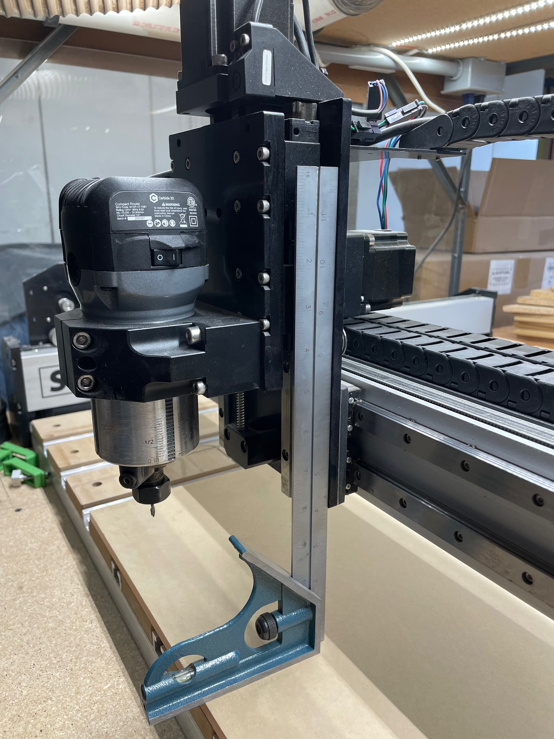
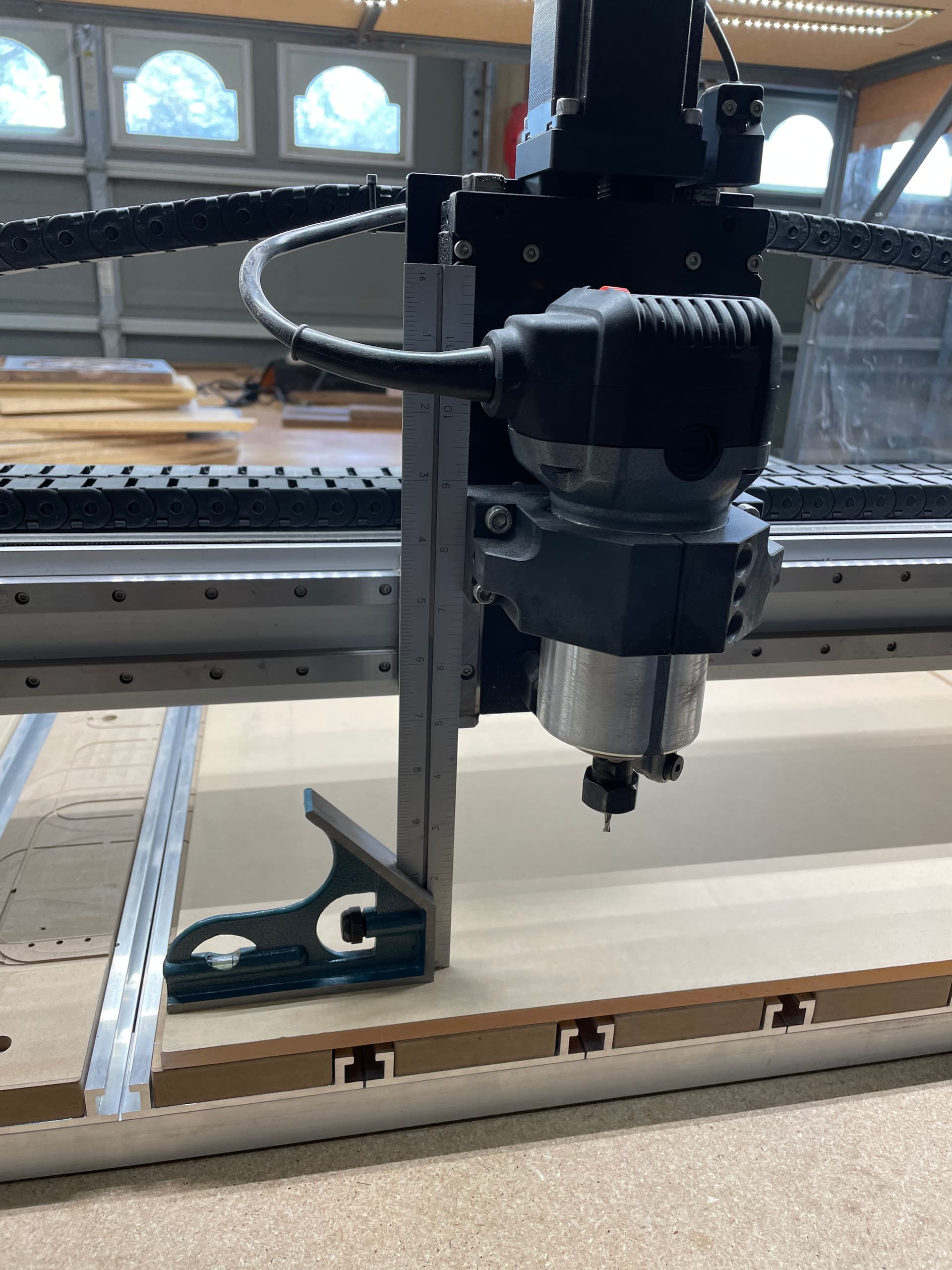
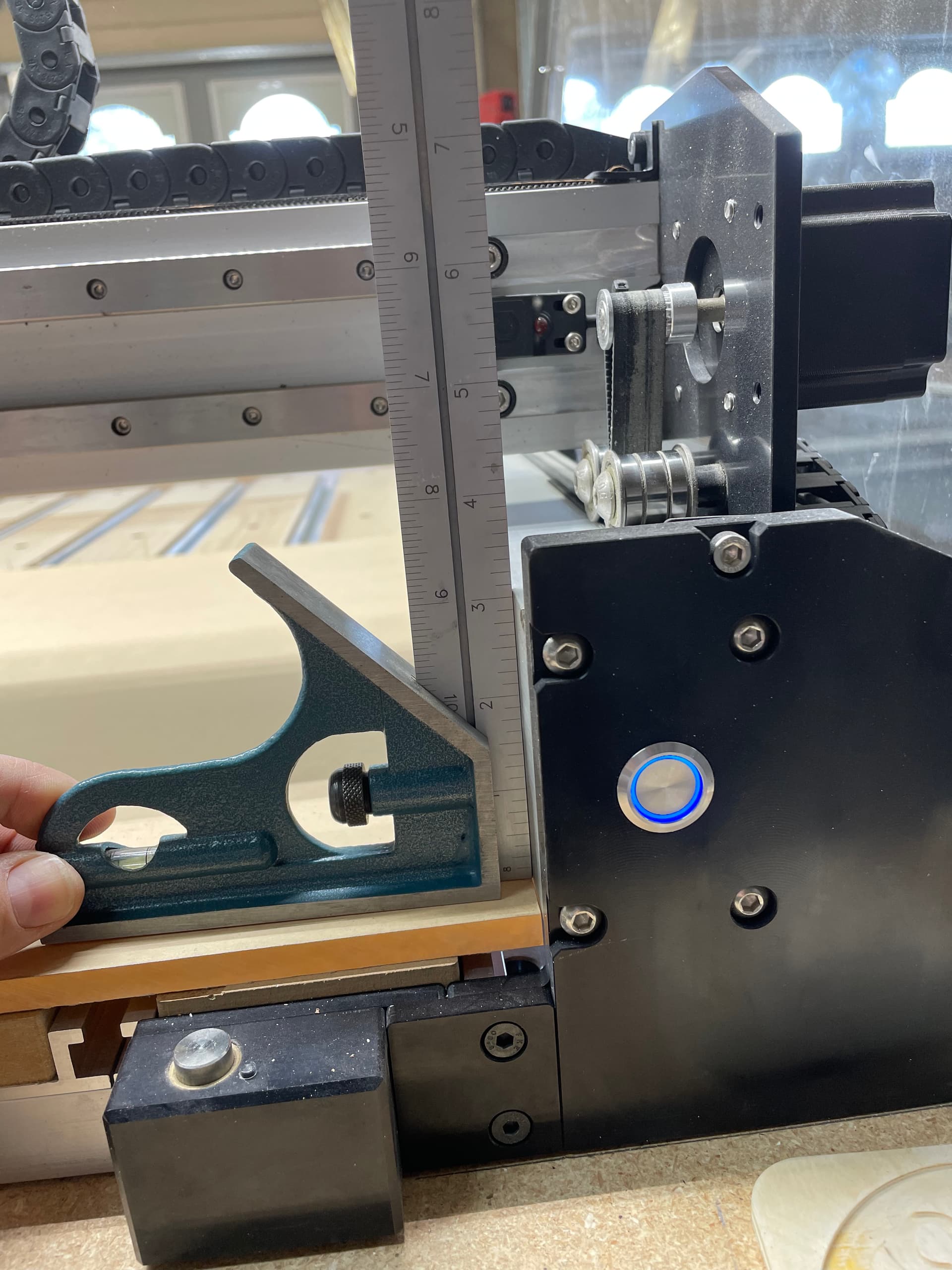
I used my square to align the x axis and sure enough it was about a degree off on the Y direction and about 0.5 degree off on X direction.
Then I checked it was square at the four corners and centers. I haven’t ran the McFly over it yet but have a high level of confidence that these adjustments were what was needed.
I also pulled the router up a bit so it was more flush in the mount and not riding on the shoulder area.