Meshcam Rotation

I have an stl imported into meshcam (6). The part and machine axis are aligned (and not in the exact middle of the part, on purpose). Rotating the part around the z axis rotates around some mysterious axis (looks like the middle of the object) not around either the part or machine zero axis. Any way around this besides rotating the part before importing it into meshcam? This is pretty irritating.
@robgrz - Is this the way it’s supposed to work?

@mikep, that’s the way MeshCAM has always worked. It rotates about the center of the geometry. When I need axis direction and origin both proper, I pre-position the geometry in CAD before exporting the STL.

Randy

@mikep
Im going to make another Star Wars reference.
Add Tie Fighter Wings to your part to offset the centerline from the center of the part.

I’m not saying it suddenly broke, or even necessarily wrong…I’m saying it’s kind of irritating that it doesn’t use the part axis which would make more sense to me. I got around it by doing as you say, I rotated the part in CAD first, and export an stl in both orientations, but it would have been a lot more convenient to rotate it in meshcam from the same stl. I have a feature in the middle I’m using for machine zero, and I aligned the part zero with it. Here’s my (goofy, I get it…) use case: I have a part bigger than the bed. I can’t tile it “off the end” of the bed like you would on something with an open chassis and just move it along an axis (shapeoko) because there is a length pin on the right of the table, and the back of the enclosure in the way on the nomad. So to do both ends of this part, the only way I could make it work was to rotate the part 180 degrees - first machine one end, then rotate 180 degrees and machine the second end. To do it all in meshcam would have been nice instead of needing two different stl’s.

@mikep, I’m not sure I follow. The gcode from MeshCAM is output relative to the Program Zero, and you can set Program Zero to the geometry origin irrespective of whether the part is symmetrical or not. Program Zero might be entirely outside the geometry, for that matter. The rawstock is always calculated relative to the geometry boundaries, so it won’t always be symmetrical relative to the geometry origin.

Rotating the geometry in MeshCAM is just for the purpose of getting the orientation as you want it. Position is entirely dependent on the Program Zero, irrespective of where the part is physically placed in “MeshCAM space”

Randy

I’m not describing this well.

The part I need to make is bigger than the table on the nomad. I can’t just mill part of it, slide it down, and mill the rest because of clearance around the table (back of the enclosure and the tool length switch on the right of the table). The only place to let the part hang off is at the front of the table. That means that to get the “second half” of the part onto the table for milling, it needs to be turned around 180 degrees. The part isn’t symmetrical, so I need a location to use as a machine zero that I can set the machine to when I rotate the part on the table because I’m surely going to move x/y a little when I do that. I used a 1/4" hole that I can align with a dowel in the collet (which I will do differently in the future…but it’s what I was doing this time). This way although both the x/y axis of the part is moving around, I can still get aligned to it for machine zero. The part axis is in the middle of this hole.

The pic shows the second half being milled, that might make this easier to understand. The material in this case is way bigger than it needed to be. The first half was done with the known straight edge (on the left in this pic) on the right against a couple pins. Then I rotated the whole thing and put the straight edge up against two pins on the left to do the other half. The shoulder bolts are there only for alignment of the edge of the sheet so I know it was turned exactly 180 degrees, no more, no less.

It came out well, with only a couple thousandths of misalignment between the two halves, which is fine for what I was doing. This isn’t the longest part I need to do this way, this particular one would have worked with a more common “slide it down” method, but I was trying to get the process figured out for a part that’s another 6 inches longer than this one.

So, all that said… I wanted to rotate the part in meshcam around the part axis so I could generate the second toolpath (for the second half of the part). Instead, I needed to re-export the part from cad turned 180 degrees, which is less convenient. If I was doing a more standard tiling operation, I would have set the machining area to about half the part, put the zero onto some feature I could find, generated a toolpath, then set the machining area to the other half overlapping that zero, and generated the second half, without going back to the cad software. Because meshcam won’t rotate around the part axis, I can’t use that to help me out here.

@mikep, thank you for the additional description and the photos. I think I’m the one who is not being clear (or just misunderstanding still what you want to do).

When you first bring the geometry into MeshCAM, use the Set Program Zero command to put the program zero at the geometry origin (which I understand is the center of your tooling hole). Reset the Z position if you need to (i.e. top of stock/bottom of stock, etc.) which won’t change the X and Y coordinates.

It doesn’t matter where the geometry came into MeshCAM, since the gcode is generated relative to the Program Zero and not the physical location of the geometry zero.

After you generate the first toolpath, rotate the part and reset the Program Zero again to Geometry Zero (which will still be fixed relative to the part, wherever it is). The second gcode will be generated relative to Program Zero, which is now still located at your geometry zero so it didn’t shift.

You can either physically rotate the part around the tooling hole to retain the machine zero, or re-zero the machine at the tooling hole, depending on how you rotate the particular part.

I’ve used this technique to coordinate new machining on an existing part, where I can zero on an existing feature wherever it happens to be. Am I still falling short on what you need to do?

Randy

1 Like

Ah…got it. I hadn’t thought about rotating and then moving the program zero again. That would work too and keep from needing to go rotate the part elsewhere.

Given that the part zero isn’t used for anything I can find (ie. not rotation, and it’s irrelevant to program/machine zero) I’m not clear why it’s even shown in meshcam. I still think it would be nice to be able to rotate around an axis not “the middle of the part” - maybe be selectable between program axis, part axis, or the part center.

Ran through the process today, using (mostly) @Randy 's recommendation. After rotating, I set the zero to the middle of the material edge. Then I matched this up with a small hole in the material (so the material was slightly wider than I told meshcam it was). The only problem I really had was that after selecting “lock stock dimensions” … they aren’t locked if you do the rotation. Again, not the end of the world, but kind of inconvenient.

Here’s the setup I used. I made a pallet for the material to be stuck to that has two parallel sides. Once the material is stuck to it you can turn it 180 degrees accurately. Had to get a little creative with the clamping because of a touch of overhang of the material over one side of the pallet. I stuck a dowel pin between the quoins and the side of the pallet, so the material could overhang. Did the same thing when I rotated it. The purpose of the pallet is so there is a set of accurate edges for the rotation, no matter what the raw stock looks like.

Took a couple tries to get things glued down right such that they stayed stuck through the whole milling session… All I can say is to read the directions on the can of super 77…don’t just assume you know what you’re doing… :slight_smile: It’s glue in a spray can. How hard can it be, right?

This particular part is 9.6" long. This method would be good up to ~15" (less than 2x 8").

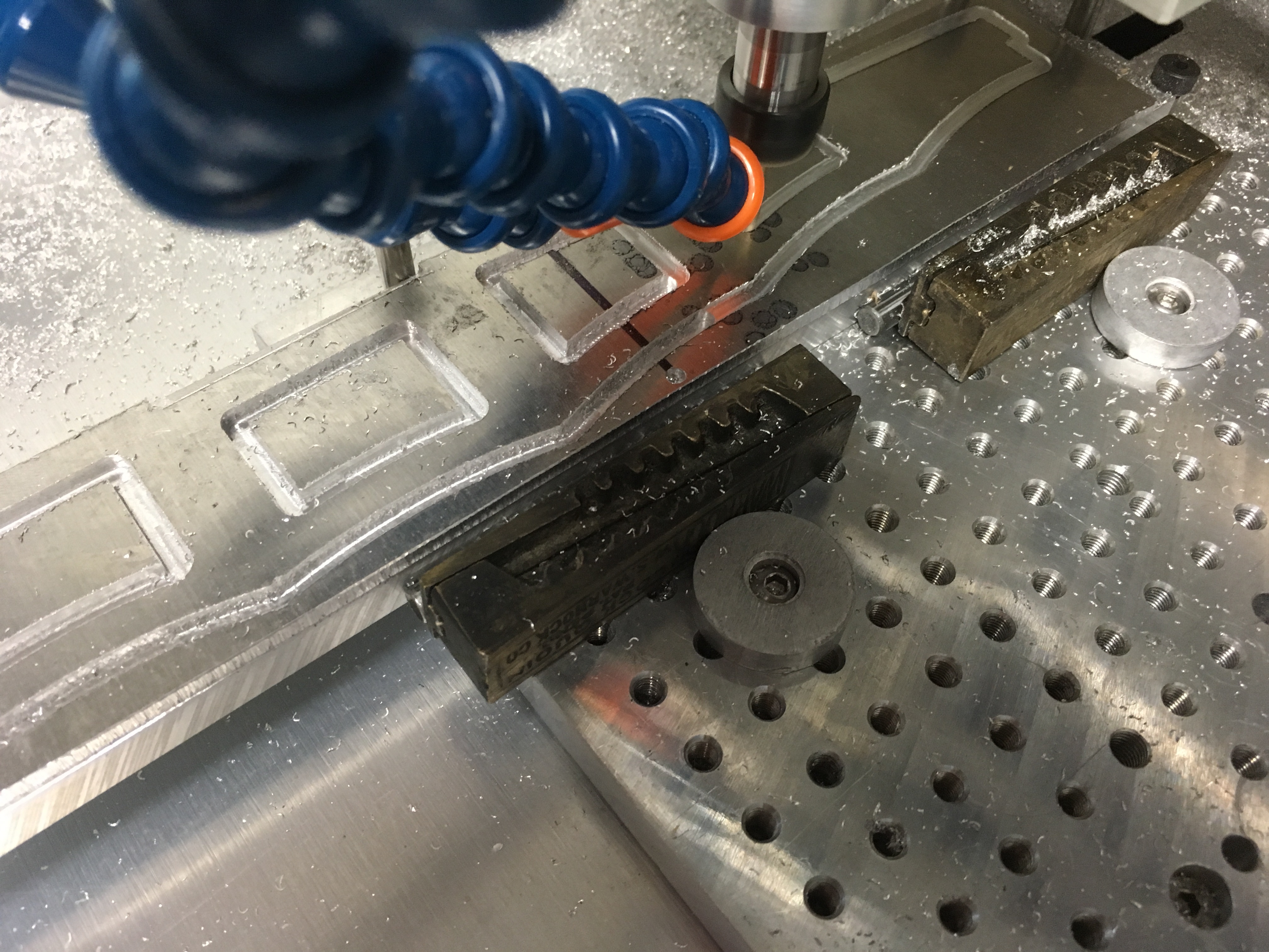
Here’s cutting the first half. There is an alignment hole (used for zero) in the stock on the left side of the black line. I clearly could have cut further during the this first half.

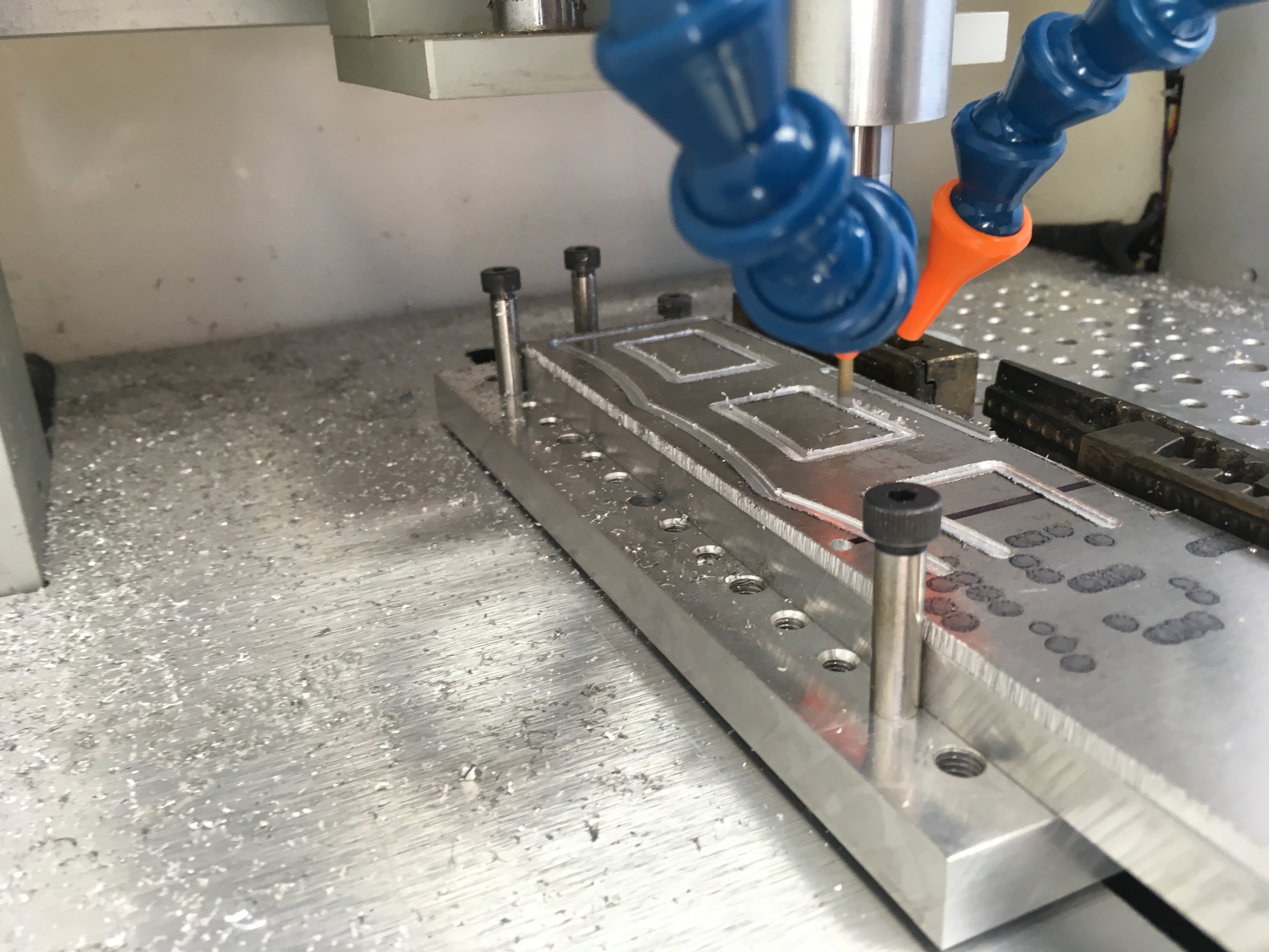
Here’s the second half. You can see the alignment hole on the right side of the material in this one. This procedure works pretty well, but I need to do something different to pick up the zero, it didn’t come out exactly on where I had wanted it, it’s off my a touch in X (and probably Y). Maybe a pointer and a scribed fiducial next time.

2 Likes