Carbide Motion is misplacing some of the design elements, created in carbide Create.
Pockets and borders are carved correctly in both practice sessions, but when text is carved, both time it started to low on the canvas. Any suggestions. All appeared fine in the preview in Carbide Created.
The paths are different with respect to the lettering. Can you post the .c2d files associated with both of these test cuts? Do you recall if you had to rezero X and Y prior to the v carve or did you only rezero z? I am far from an expert but can look at the files until the experts show up.
I have the Shapeoko Pro XL. There is quite a bit of buzzing from the left side belt. Also I notice the right side of the gantry moves up and back before the left side. In other words the left side of the gantry always seems to be “catching up” to the right side.
Put a bit of tape on the Y-axis pulleys (so as to more easily see their rotation)
Power up
Initialize
The machine should move the Z-axis and home it as normal, then try to move both X- and Y-axes — the X-axis should home as expected, while the Y-axis motors should turn until they time out — do they turn evenly and in synch?
Hey! No re-zero was done at all during the cut. The machine asked for tool changes and then measured at the Bitsetter. Here are both versions of the job.
I suspect once the belt/y axis issue is resolved, you will see improvements. It looks like the carving itself (pockets, lettering and borders) is mostly consistent which suggests to me the shift in Y occurs during rapids and this may align with the belt/y axis issue. If the v carving with the 90 degree does not also sharpen up, I would check the tip for a nice unchipped point.
Hey, Mr. Bozo. Discovered the source of my problems this morning. I ran some tests and discovered that the Y2 motor (left side) is not working at all. While in “Jogging” mode, I removed both belts and jogged back and forth in the Y direction. The right side motor spins freely and smoothly. The left side motor stumbles and vibrates, and will not complete even one revolution. The right side motor is moving the entire gantry all by itself. No wonder my design elements are off in the Y direction. I have an email in to Support. Hopefully a new motor will be in the mail shortly. After 30 days of ownership I have yet to successfully complete a cut. Still anticipating that great day. Thanks for your input. Just thought you would want to know.
Just sent in an email outlining the problem. Long-story-short, the left-side Y motor is not working at all. I attached a short video so you guys can see.
Thank you for the update. I purchased a used SO3 XL more than 2 years ago and still don’t fully appreciate how issues with motors, belts, and pulleys can manifest themselves. It does seem that V carving letters often brings to light issues and that toolpath might be a good periodic performance qualification (with a few long rapids thrown in) to confirm things are mechanically okay for wood.
Please post your shop sign after the motor issue is resolved and keep us informed if there are any other issues. I learn more from this reading this forum than from cutting.
I’m about to pull my hair out. Thank God, I’m actually bald.
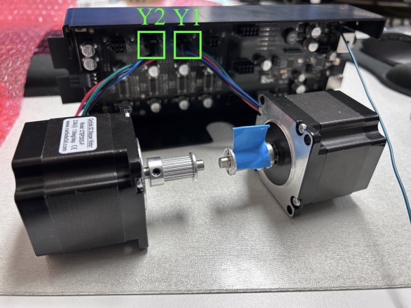
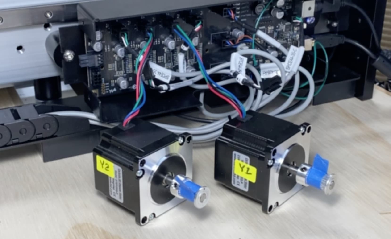
I contacted the people at Support. Below is a picture of what they wanted me to do. Basically, disassemble the motors from the machine and plug them directly into the motherboard to see if they rotated in sync and smoothly during an initialization attempt.
I followed instructions to the letter and ran the test as instructed.
I fully expected the bad motor to reveal itself; did it? Of course not; it behaved perfectly. I then switched the motors on the motherboard and ran the test again just to be sure. Same results. Both motors spun smoothly and perfectly in synch.
At that point, I figured something was wrong with the connections, so I reassembled the machine and rewired up the connections just has they were before. I conducted an initialization.
Did the motor misbehave? OF COURSE NOT! The machine ran perfectly fine! Now I know how my students felt when I taught computers back in the old days. They would raise their hand and yell across the lab, “Mr. Massey this computer is not working. It’s messed up.”
When I walked over the computer was working perfectly fine. My student would look at me and say, “Honest, it wasn’t working.” Evidently the Shapeoko machines know when you are ratting them out to the support folks. Amazing!
So, currently my machine is running perfectly. Both Y motors are in synch and running smoothly. The vibration on the left side is gone. The gantry is moving to and fro as if on glass, being powered by both motors instead of just one. I have no idea what I did (aside from following instructions from support). Did the motor reset itself by being connected directly to the mother board? Who knows? Not me.
I even got my BitZero device to work for the first time. Unbelievable.
I’m tired now. Going out tomorrow to try for a third time. Fingers are crossed. Wish me luck.
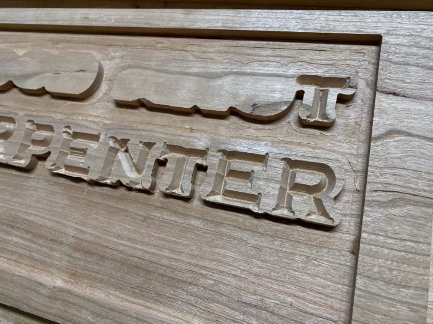
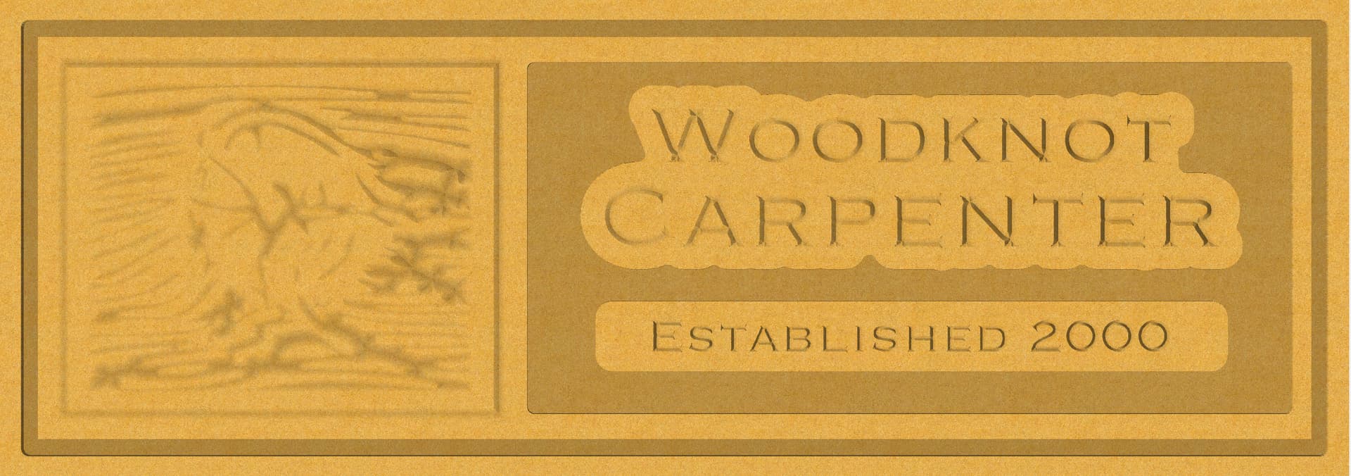
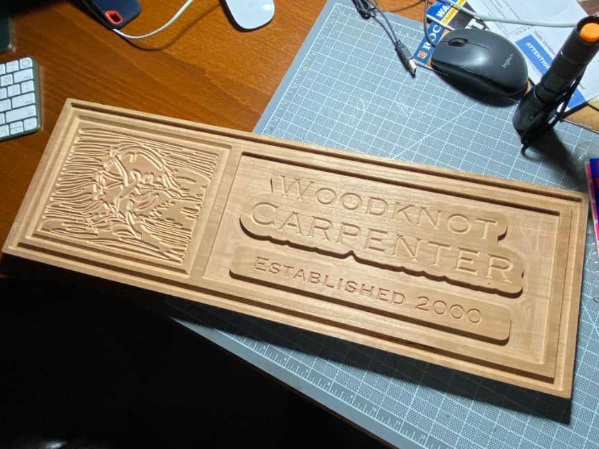
I’m smiling guys! Third time was the charm. After getting all of the bugs out of the machine, I completed my first project: a shop sign. My wife says I was a bit too ambitious for my first project. She’s probably right, but that’s how I roll.
Thank you to everyone at Support who coached me through all of the newbie headaches and questions. You guys are awesome!. Also thank you to all of the forum members who contributed comments and advice. I think the Carbide community is great. I learned much and will carry it forward.
Anyway, onward and upward. Now that I know a bit more about what I’m doing, the sky is the limit. You guys are much appreciated.
If you do not reach for the stars or you wont catch them. There is a song on the radio that the lyrics are something like this:
You have to chase your dreams because the dreams wont chase you back.
There is no one that never fails but failure leads to success. Your sign is very nice. Please explain how you did it. Since you are the Woodknot carpenter are you a knot head?
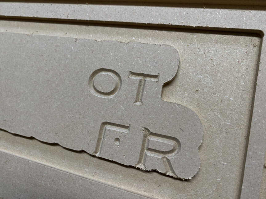
Things are looking much better. But I want to be sure you are ‘all the way there’. Can you post a closeup of the “W” in woodknot and the “N” in carpenter, the font name used for each and the toolpath parameters (including the bit) you ultimately used to cut?
Cheers.
Your patience and perseverance paid off. That is a very nice project. A lot of folks underestimate the skills needed to delve into CAD/CAM and it can be very daunting. There are literally a lot of moving parts to master along with no small amount of computer expertise.
The main border on the outside edge was a pocket cut with a 1/4" flat end mill. I was warned not to attempt a slot with a contour tool path with this cutter. However, the border immediately surrounding the main art was a contour cut, done with a 90° V-bit no offset, .1" deep.
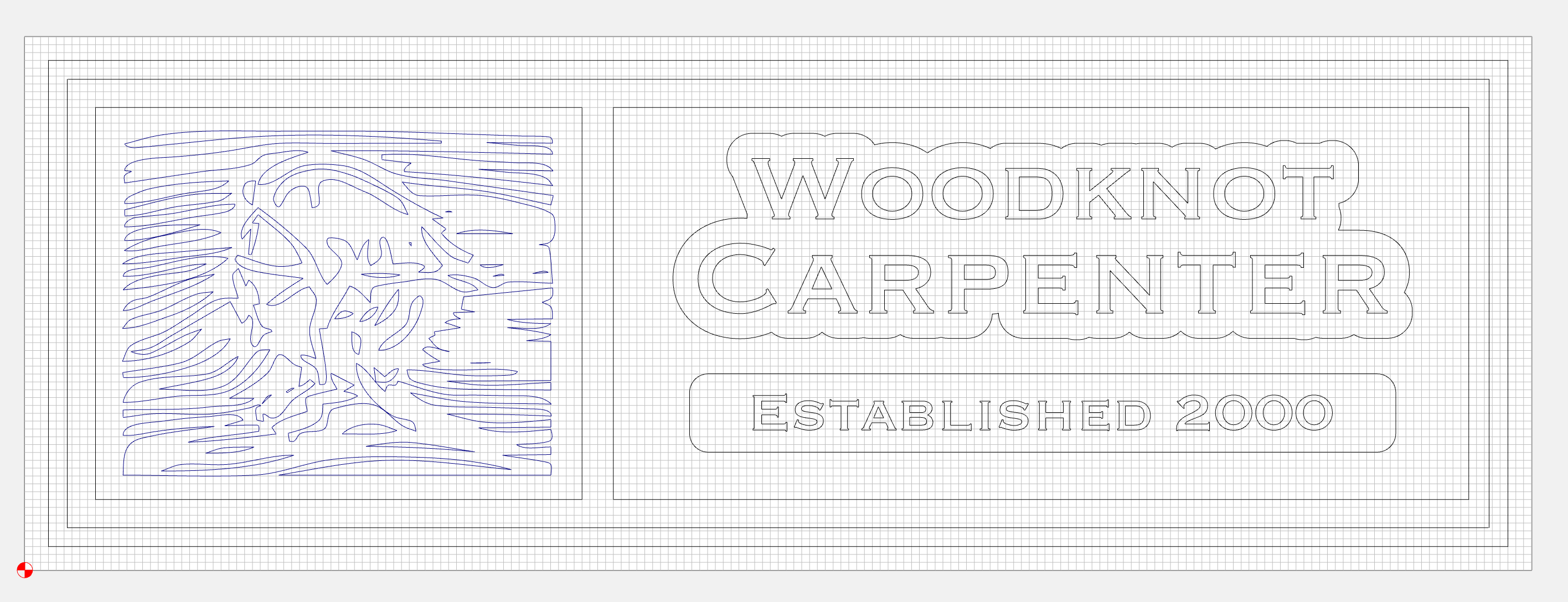
After placing the main text, I selected both lines of text and put an “offset” around both of them. The smaller text was placed inside of a rectangle with a radius at the corners. I then surrounded all of these elements with a rectangle, and used a Pocket cut with 1/4" end mill to create the pocket around those elements. I did not use “Rest Carving” as I do not have CC Pro, nor have I done it before.
The artwork on the left was cut from an imported black-and-white image which was traced into the work area. It was cut with a 90° V-bit to .18" deep, it was a V-carve cut.
I failed to realize that I could have done an Advanced V-Carve cut on the text and artwork. They probably would’ve come out even better.
The main text of “Woodknot Carpenter” was cut with a 90° V-bit; depth of cut was .085". I think I messed up there; it should have been a bit deeper.
The smaller text was cut with a 60° V-bit,.1" deep.
I might try the entire project one more time with some fine tuning, as this one was done on the back of one of my earlier failed attempts. Let me know if you have more questions.