Scratch-built small-scale model railroad track is often constructed using nickel-silver rail soldered to crossties cut from single-sided PCB. Since the electricity for the locomotive motor is transmitted through the rails, the PCB foil needs to have an “isolation gap” cut between the rails.
I have machined some turnout (switch) bases from a sheet of 1/16" (1.6mm) paper-phenolic PCB.
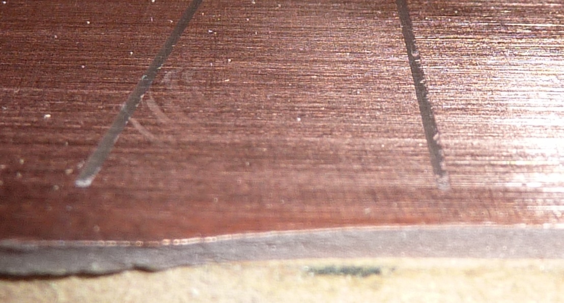
First I cut the iolation gaps wtih a drill-pointed endmill from Melin, filled with gel superglue, and scraped and sanded flush with the foil surface.

and a closeup
Then I machined the crosstie outlines .040" (1mm) deep, and the outlines through the whole board.
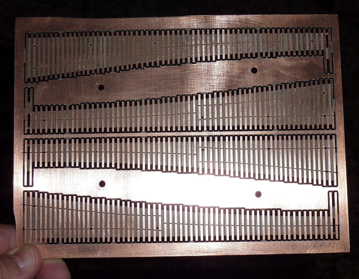
and a closeup

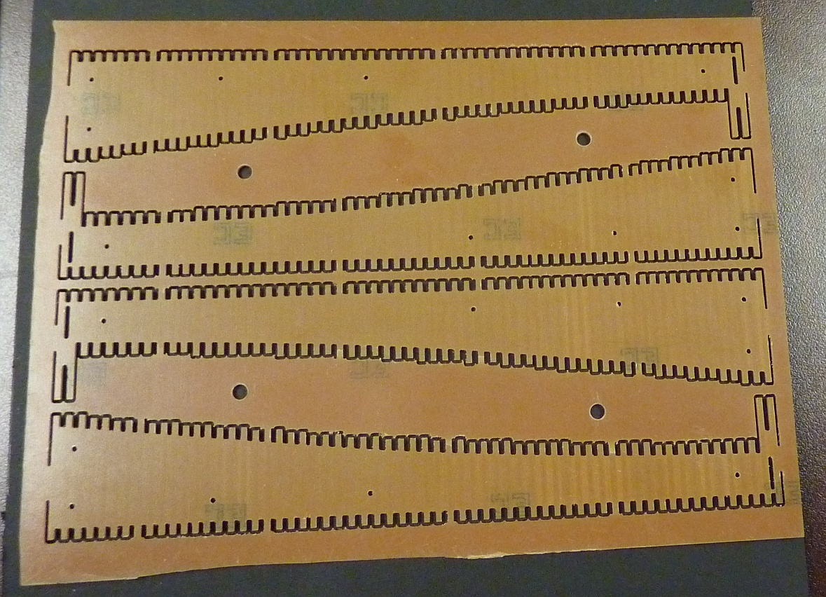
I defined tabs to hold the bases into the parent material. The paper-phenolic is a little more brittle than I expected, so several of the tabs cracked back into the crossties, which is not a problem in practice, since it is only part-way through on the bottom side. You can see the lighter lines across the tie ends at the tabs in the following photo. On future bases I will probably tab two adacent ties in each location.
And here are a couple of the bases in place on my full-size layout template.

I noticed a flaw in my layout–the bases need to be separated by a tie gap.
The bases have 1/16" (1.6mm) holes on the track centerline near each end which I’ll use to attach track soldering templates (which I will machine from thin phenolic sheet) with 0-80 screws. I’ll also use the “frogs” that I showed in the Nomad and Bronze thread.
I bought the raw PCB from Jameco Electronics
I used a 1.0mm square-end carbide endmill at 10000 rpm, a stepdown of .020" after an initial stepdown of .005" to just machine through the foil, and a feedrate of 12 ipm.
I used SheetCam to generate the toolpaths from a DXF output from VersaCAD, the 2D software I’ve used since 1989 (I bought the Windows version in 2004 but still have the 5.25" double-density install disks from the original DOS version)