Hi everyone, i’m slowly getting to grips with flipping parts on my Shapeoko for accurate 2 sided cutting. My process is;
Work is cut off a centre “zero”
I know where the zero location is on my base board and have two alignment dowels referenced to this zero
The same alignment dowel holes are cut in my work piece.
Position the work piece onto the alignment dowels. Cut one side, flip, cut the other side.
One unexpected issue i have run into (i think) is that i don’t have a method to check that when i move the machine to my “known” zero location, that is actually on the zero that my alignment dowels are referenced to. I’m going to cut a 1/4" hole at the zero location and position the bit in this to check my zero before each series of cuts.
What i’m ultimately trying to achieve though is repeating this process on four individual locations, in a single cut. ie 4 work pieces being cut at once, flipping, then accurately cutting the flip side for all four work pieces in the next cut.
Does anyone have experience with this? Any tips on how to achieve it?
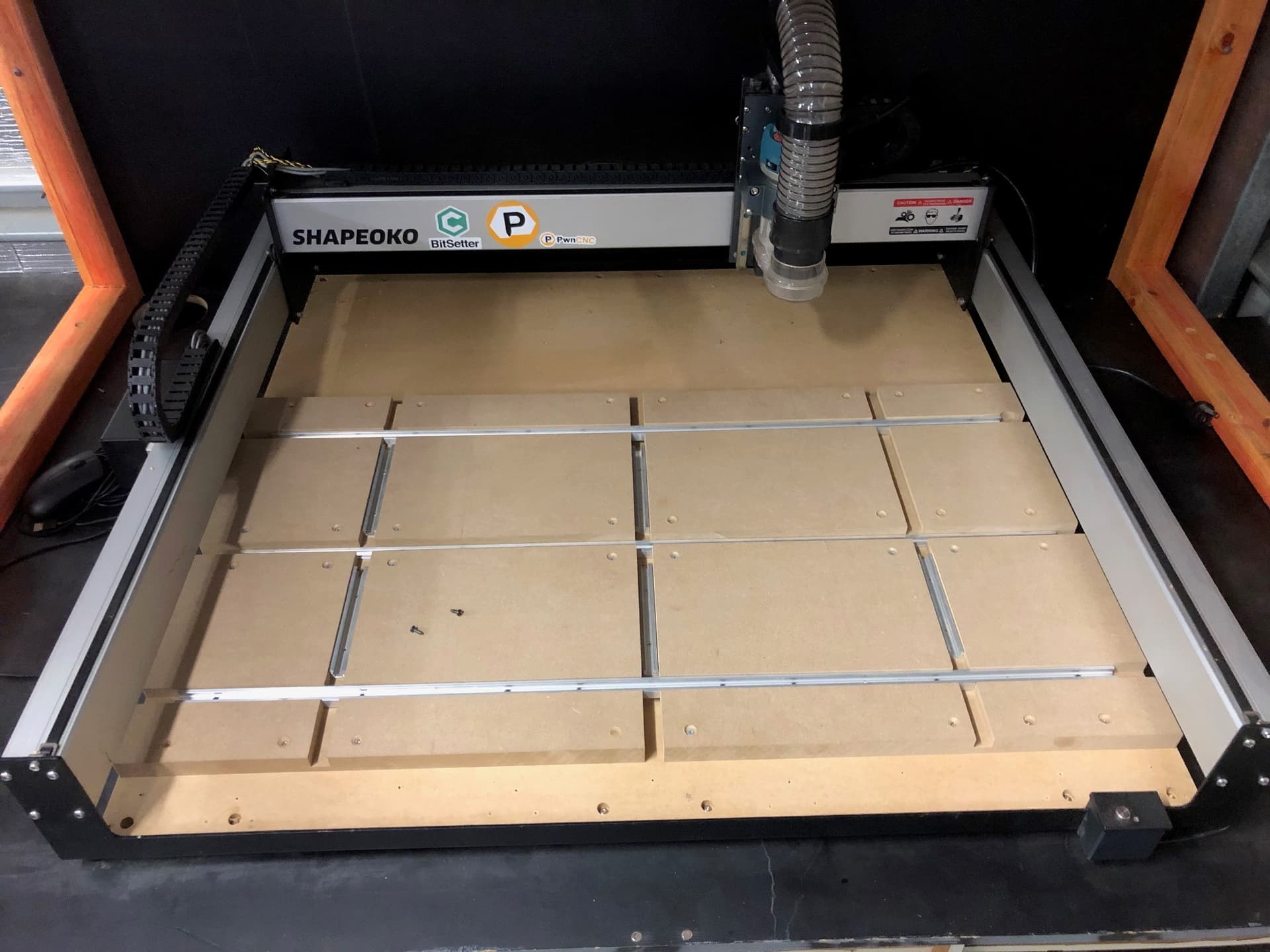
I have my baseboard set up with 4 “stations” (photo below) - the alignment dowel holes are not cut yet in this pic.
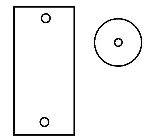
I would machine a rectangular piece like this that you can set over your dowel pins and probe off of to check your zero. Or if you only wanted to check one dowel, you can make a round piece.
Is the bitzero a simple pin pulled to ground connection?
If so would it be sensible to mill a bitzero v2 sized round hole in a piece of aluminium as part of your layout jig, connect it up to the controller and then just tell Carbide Motion that it’s a bitzero v2 and to probe the hole for X, Y ?
After that one could either just move a known distance (G54, G0 X… Y… ) to the other jig points and say “zero X, zero Y” or dive into the dark depths of multiple WCS beyond G54?
Hi Liam - my thoughts are along these lines but with a manual check of the initial reference hole, instead of probing with a bit zero.
The work process would be, as long as the centre of the other jig points is known;
Manually probe for X/Y on known reference hole at centre of workstation 1. Zero X/Y
Complete a full cut at work station 1
Jog to the centre of work station 2, zero X and Y
Complete a full cut at work station 2
repeat process for work station 3 and 4
How i compile that into one cut file i’m not sure…need to learn about Gcode i’m guessing. Does that sound feasible? Any tips on compiling multiple files into a single cut file?
My main concern is that given i have a reference hole in workstation 1 that i zero on, and that the location of all alignment dowels and centres of work stations 2, 3 and 4 are at known positions relative to this - will a base board of multiple bits of MDF etc retain enough dimensional stability to get accurate flips on all 4 stations?
Hi @kelaa - i’m more concerned with ensuring my X/Y is zeroed on the the centre between the alignment dowels than zeroing the Z. Thanks for the reply though.
If you’re looking to automate then replacing your manual zero with a good automatic will be an effort saver once you’re confident it works.
To maintain relative position of the four jig locations I’d suggest making up a single full jig which has all four workstations on a single spoilboard so that you don’t have to probe for zero four times, if you machine the jig on the Shapeoko then you know where the four jig locations are relative to each other and you just need to make sure the jig is on the machine square.
As for a single file, you could go about it the ‘easy’ way and set up four instances of your workpiece in your CAM spaced out as they are on the machine and then just set up tool paths to cut all of them. Or you could venture into multiple work coordinate systems in your CAM (assuming you have Fusion or similar) and then tell the Shapeoko where your four jigs are, see this thread for some info
I have not done multiple WCS so I’ll leave it to others to say whether it’s worth the effort through Carbide Motion or not.
If it is the same 4 parts and you have a known location on a fixture for all of them, you could use a toolpath pattern in Fusion 360. Zero off the fixture and you would be good to go.
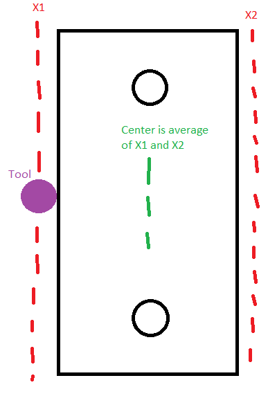
I learned the basics on manual mills with DROs, so I may be inclined to probe manually more than some. What I was saying is that you probe the edge of the rectangular piece like this:
Similarly for the Y direction. Your subsequent probes you can reduce to probing one X and one Y if you want to save the time since your zeroing jig piece dimensions aren’t changing. The advantage of still probing both sides of each axis is that you can reduce errors by averaging and in case you changed your tool size. You don’t need to measure each set of dowels, since presumably you made the holes using your CNC, so the relative spacing between the 4 sets of dowels should be known already.
As others have mentioned, if you have a BitZero, you can semi-automate this if you machine a slot for the BitZero in the proper location on the jig piece.
There’s no reason (if you have room) that you can’t cut a pocket somewhere on your “fixture” for the BitZero to rest in (tightly). If you do it right, you can get your X, Y and Z from that. Jus’ sayin’