N00b Experiences with a JTech Photonics 4.2W laser & S3 XXL

As requested by @stutaylo, I am documenting my experiences with installing a JTech Photonics laser

I purchased the laser after speaking to Jay Johnson of JTech, and asking questions including, should I just buy the most powerful one and turn it down as needed (no, I probably only needed the 4.2MW), how to install, uses, etc. Jay was very helpful and gave what felt like open and honest advice.

JTech are located in Texas, and can be reached at 713-826-2122 between 9am-5pm CST M-F.

After unboxing the unit, and laying out all the pieces, I started my install. The included instructions were a little lacking, but their desire seems to be that you go online to make sure you are always referencing the most up-to-date documentation, which can be found here..

The install goes in a couple of phases. First off, I had to dismount my z-axis carriage and reverse it as the mounting holes for mine were on the wrong side, and the 3D printed mounting bracket is designed to install on the RHS of the spindle mount. This only took five minutes, and I quickly moved on to routing the cables. The laser assembly has a two-ish foot pair of pigtails which allow you to run the main wires back to the control board through the S3’s cable track and leave them there permanently and just quickly disconnect the laser when you are not using it. This took me a good 15 minutes, but left me with plenty of spare wire at the controller board end, which I was relieved about (the cables for my S3 limit switches were too short to route into the control box when I first installed, and I didn’t leave much spare at the limit switches).

The next step was to install the quick install pins for the control of the laser by the S3 control board. This is a little pair of pins connected by a small plastic bridge which you push into the two holes located in the top right hand corner of the S3’s control board - specifically they sockets marked GND and PWM. PWM stands for Pulse Width Modulation and is the method by which the control board can vary the intensity of the laser when cutting or engraving - this will have the red wire of the control cable connected to it. Pushing these pins into the S3 control board is a little nerve-wracking - push too hard and you might worry that you could crack the control board, but if you don’t push hard enough they don’t go in. There is a short video here, but they include a little 3D printed tool which holds the pins and plastic bridge and gives you a much better bridge than trying to use the connectors on the jumper cable like I initially tried. I would recommend wiggling the pins slightly as you push as they will go in just a little easier.

At this point, it’s prbably worth pointing people who have already purchased and need further install help to these videos:

Myers Woodshop - https://www.youtube.com/watch?v=OgQjogfBKdM
(more as I find useful links)

Once that is taken care of, you can go ahead and decide on where you want to mount your laser controller and route the wires accordingly. Make sure you check page 7 of the manual for the correct connections for everything - it would be great if the cables were labeled, and the ports on the controller too, however they aren’t.

With the wires routed, the board and laser installed and connected, and the power brick connected, you are ready to start using the laser.

Edited 2.28.19 to account for my delusions of grandeur - these lasers are measured in regular watts - not megawatts!!!

< This is currently as far as I have got. Please post with pointers or improvements to this guide, or with questions that I might be able to help with - I will update this as I go - Thx! >
4 Likes

Reserved for future info - useful tutorials, etc

Thanks! Now if someone would just do this with one of the 70 dollar ebay lasers since i’m to cheap to go Jtech.

1 Like

Thanks for documenting your experience with this laser, how did they/you determine what power level you would need for your application?

I frequently need to cut 3/32" extruded acrylic (plaskolite optix) and am exploring laser as a way to do it quicker with less mess, but I am having a hard time determining how much power I need…

Hi Stephen. I would recommend calling Jay at JTech and outlining what your needs are, he is very knowledgable and will be able to recommend the power of laser you will need for your purposes. From what I remember, I think the 4.2W version should work. In fact, in checking their website, the APPLICATIONS page says:

" The 2.8W laser kit has plenty of power to engrave and cut through acrylic. If you want to just engrave, then it is a fast and easy process. If you want to cut, then it can be done at around 60 mm / min with three passes for 1/8″ acrylic. It works with many types of acrylic including opaque and semi-transparent."

If I remember correctly, a more powerful laser allows you to up the cutting speed, as opposed to cutting deeper. I wasn’t worried about the $100ish cost difference between the 2.8W and 4.2W, so I went with the middle option. But call them, leave a message if you don’t get hold of anyone, and they will call you back. I believe Jay may be traveling this week, so bear with him if it takes a day or two to reply.

Good luck!

A lot of what you are paying for is a tried and tested solution that is tailor made for the shapeoko. If you want to engineer the heck out of a particular solution, have fun with the eBay option - it is only $70, after all. But it you want to get on with making stuff, the full kit allows you to mount it straight up and be setting your wasteboard on fire within an hour or so!

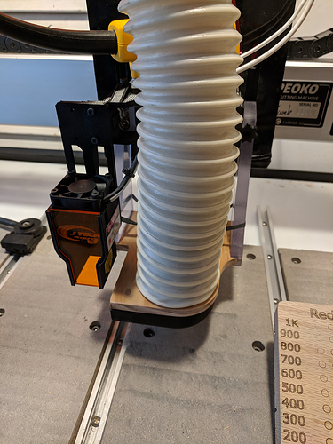
So, figured this is as good a place as any to post my setup and first light results. I got the magnetic “dust boot mount”, but I installed it on the left instead of the right (for easier access angles in my workspace). I also made a custom “SmokeSucker” adapter that slides in where the Suckit dust boot would normally go.

The SmokeSucker plate is a piece of thin pine that happened to be about the perfect thickness for the dust boot slots. I cut it on on the machine, then glued in a 3D-printed hose adapter (not visible) and a 3D printed vacuum director (black part – it’s open toward the laser, and the bottom face also has an arc cut out on the end facing the smoke). A screw, knob, and rubber band hold it in. (Easier than trying to successfully drill magnet holes in thin wood edges.)

I plan to combine bits and beams in my projects (as that’s the whole reason I wanted a laser). To make that easier, I definitely wanted to be able to probe to set focus. Alas, it’s hard to clip a ground lead to a laser beam, and even if you could, the beam won’t conduct well unless it’s really powerful. :rofl:

The most straightforward solution is to probe with something else and note the offset.
So, I bottomed out a designated carbide blank in the router (with the collet just keeping it from falling) and probed with that. I then set the laser at a height compatible with my planned work, focused it precisely, and recorded the Z offset from probe-zero. Now I can return to the focus distance by probing with the designated carbide specimen, jogging the offset, and zeroing Z.

When it came to focusing the beam, I grabbed one of my cameras, threw on a nice telephoto zoom lens, and stuck it on a tripod next to the machine. I stepped the laser power down until it was as low as I could get it to go without it extinguishing completely. Then, using the screen, not the optical viewfinder, I zoomed down to the laser spot and then blew up the dot as far as the camera could go. With that, I could clearly see the size and shape to dial in the focus just so.

The same offset concept should work in X/Y, so to find the offset between the spindle axis and the beam axis, I loaded up one of my pointiest of pointy bits, slapped a piece of scotch tape on the spoilboard, and made the tiniest hole I could make. Then I turned the laser on at minimal visible power and jogged until the beam went right down the hole. (The tape made the hole much easier to find and hit.)

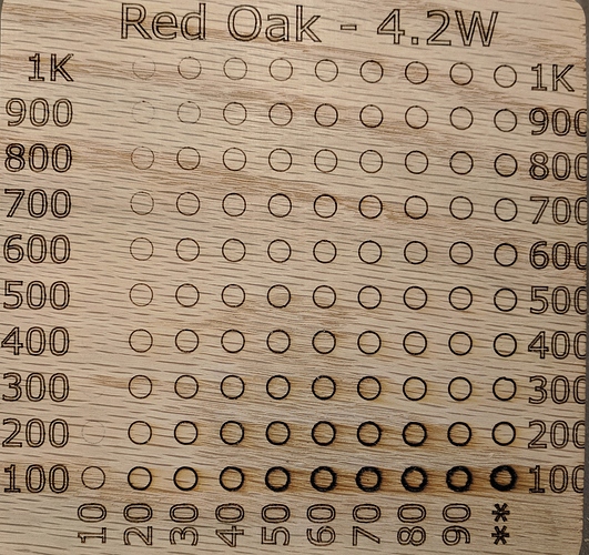
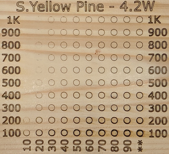
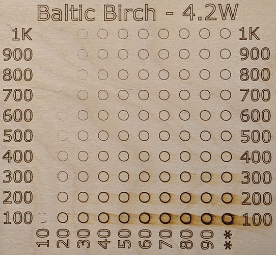
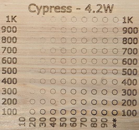
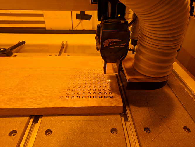
With everything together, I first threw some Hello, World at the laser. With that out of the way, I figured the first thing to do would be to get some basic feeling for power and feed rate. I used the Inkscape extension to generate G-code for one 5mm circle, then used a little python to make a 10x10 matrix out of it with each column being run at a given PWM percentage and each row being run at a different (mm/min) feed rate. I ran that job, selected a reasonable feed and power, and ran a second job with the labels. I figure I’ll likely run a similar panel on each material, then keep them for baseline reference.

Anyway, that’s how I spent my post-Crew Dragon docking/ingress/welcoming ceremony day. Now, I think it’s about time I grabbed some breakfast… lunch… supper? I don’t care what you call it! I’m hungry! :joy:

9 Likes

@ClayJar - Hey Nathaniel - this is great information! Especially the processes for zeroing out and for focusing your laser. You have definitely earned your breakfast/lunch/supper!

How did you work out what a “compatible height” was for your material?

Would you be up for including the GCode file for that matrix here for others to be able to use as a “power test” template?

1 Like

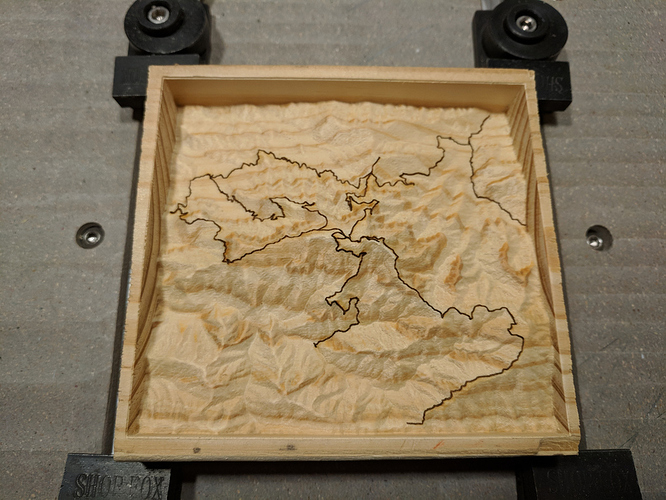
What determined the “compatible height” for my projects is their Z depth. Since I want to laser engrave the trails onto my terrain relief model carvings, which generally cut up to about 31mm from stock top. I had to have at least that much clearance between the bottom of the laser shroud and the stock so I wouldn’t crash the laser shroud into the walls of the model when the Z axis drops down to burn trails at the lowest depths of the model.

Certainly, but with some necessary notes. This is just the circles, not the surrounding text, which I always put on with a separate job after the fact. You can just as easily use a Sharpie for the label, hehe. They’re 5mm circles on 10mm centers, zero front left, total span a bit under 100mm by 100mm (with Z completely untouched by the file). The file runs from 100mm/min to 1000mm/min, with 10 steps of power (PWM), BUT (here’s the important “but”) your max spindle speed setting has a good chance of being different than mine, so…

  • If your $30 (Maximum spindle speed) is 1000, it matches my setting and you can use the file as is. (I’ve not seen anyone mess with $31, minimum spindle speed, which is zero.)
  • If your $30 is something different, you can change it or the file:
    • Set “$30 = 1000” to change your maximum spindle speed setting, then run the file, and set $30 to your preferred value afterward. (I wouldn’t take that approach if I were you.)
    • In a text editor, just search and replace all on each of the “spindle speeds”, replacing them with appropriate values for your $30.
      • The speeds in the file are “S100”, “S200”, “S300”,… “S900”, and “S999” (not “S1000”, as I didn’t want you to hit that when replacing “S100”).
      • The speeds to replace those with are just your $30 cut into 10 steps, and it’s not sensitive enough to worry about rounding wrong. (For example, if your $30 was 255, you could do S26, S51, S77, S102,… S255 – replace all “S100” with “S26”, replace all “S200” with “S51”, and so on.)
    • Tell us your S30 value and someone will do the search and replace. :wink:

Since laser power (PWM) is sent as “spindle speed” values, there’s no universal setting. Anyway, with that caveat (and it’s really not difficult to search and replace in a G-code file, at least not for something this simple in a file that was made to make that easy), here’s my circles file: Circles.nc (54.1 KB)

If you would like a “personalized” set (or sets), I can also throw one together from any set of feed rates and power levels (any number of each, actually), as it’s just a little python script that makes it by copying one circle and filling in the blanks. I just need to feed it a set of feed rates, a set of power levels (percents), and the $30 maximum spindle speed value.

Meanwhile, southern yellow pine, baltic birch plywood, and cypress:

6 Likes

can you share this file with me? I plan on doing a video series on the jtech and this would cut back on a ton of work i’d have to do! :stuck_out_tongue:

1 Like

Looking forward to seeing this Ben - I enjoy your YouTube videos!

Nathaniel - I keep looking at these test samples and seeing a slight ovoid as opposed to a circle… slightly stretched out towards the top left and bottom right corners of each circle), is that an optical illusion due to grain orientation?

It seems most visible (imaginable?) on the Cypress test at locations like 90pwm/100 or 70/400. I also see it on the Birch at 30/500… but then if I stare long enough at any of them, they seem to shift… it’s making me doubt my eyesight :crazy_face:

Hehe, I should’ve taken some higher resolution photos (and possibly some micrographs, although I don’t have an SLR attachment for my microscope… and the throat size is too small, anyway). :joy:

The circle on cypress at 90% power and 100 mm/min is distorted a bit by char. That was far too much power for the feed rate, so the wood charred excessively. The burning reacts differently to the more and less dense portions of the grain. My SmokeSucker vacuum attachment also strongly pulls the smoke and such to the right, as you can see in the smoke smears from some of the circles.

I don’t really see that much char distortion in the cypress 70% power at 400mm/min when looking at that circle with a magnifying glass under my very bright photo lightbox. That one may not be perfectly circular, and birch 30% at 500mm/min does look like it might not be perfect. The circles were all the same gcode (except the feeds, of course), but it could’ve been something with my machine or perhaps the result of a small amount of play in the laser mount (specifically between the laser shroud and the arm to which it magnetically attaches). As for the latter, I’ve got a rubber band and a little “bracket” I printed that should make sure any wiggle is eliminated. Regardless, we’re talking about fractions of a millimeter in wood, which is already pretty good, I suppose.

I’m surprised you didn’t also note that there is a small “dot” at the top of the circles where the laser path starts/ends, as there’s a tiny bit of overlap. That’s not really noticeable unless you’re really looking, and in most cases, it’s about on par with the natural variation you get from using wood, but I had to note it to myself when I saw it. :sweat_smile:

Well, I dare say that worked out. :grin:

My first try of laser-engraving hiking trails on a 3D relief model carving. The detail is much clearer than I could get with a 0.25mm radius tapered endmill, even before painting the lines (even a 5/0 spotting brush is vastly larger than the engraved paths when you put paint on it).

It does show quite well what I was referring to regarding having to have the laser high enough to not crash into the walls. In this case, it’s a small model carved into a piece of 2x6, only 18mm or so deep, but obviously the laser shroud can’t be just off stock top when you start if you’re going to have to keep focus from the top of Mount LeConte (center) to the bottom of the Porters Creek trail (top right).

8 Likes

I actually see that in parts made on high power production lasers in aluminum at my day job. It’s not all of the time, but occasionally we’ll see a tiny burr at the start/stop point. These are on purchased parts, we don’t actually do the lasering, so I don’t know exactly how they correct it. Maybe do an overlap on purpose and adjust power on the lead in/out? Like ramping with a traditional cutter head? Just thinking out loud, don’t mind me :smile:

Dan

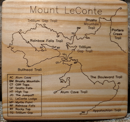
I decided the reverse side of the terrain models could use a map so people can see where things are. It was a straightforward process to take my existing trails SVG in Inkscape and add a bunch of text, but it occurred to me that there’s a good chance that most people, even Inkscape users, wouldn’t be familiar with a really useful tool that comes built in. So, first, here’s a photo of the map side of the terrain model:

The text is what I want to point out. It’s called “Hershey text”, and it dates back to the 1960s when Allen V. Hershey at the US Naval Weapons Laboratory designed it for the General Dynamics S-C 4020. If you want to read some background, here’s an article for you. What’s really useful is that the “font” was designed for what was basically a plotter, which is basically what a CNC laser is. In my case, I used the sans-serif single-line version, which is as fast and clean as type gets.

To check out Hershey text in Inkscape, you’ll find it listed as “Hershey Text…” under the “Render” option in the “Extensions” menu. You tell it what to render into Hershey text and what typeface to use, and it generates the text as a group of paths that you can then resize and otherwise alter. It’s not something you’d likely want to use to engrave a decorative plaque, but it’s great when you want to put small text labels onto a project in as clean and efficient a way as there is.

IMPORTANT NOTE: When I was working up the map, I ran across a bug in the “J Tech Photonics Laser Tool” plugin. It chokes over paths that exist in the SVG but don’t actually have any contents, and the “Hershey Text” extension does just that with spaces.

The workaround is just don’t use spaces, and the easiest way to do that is just to use a dash, underscore, or anything else where you would use a space. Then just ungroup the text, delete your placeholders, and continue on your merry way.

If you want a one-line fix so you don’t have to bother with the spaces, the easiest fix is to change line 3044 in the laser.py as follows (leaving the line indented just how you found it):

Before: if "d" not in path.keys():
After: if ("d" not in path.keys()) or (path.get("d") == ''):

And for more information about the Hershey Text extension, what it does, how to use it, and so on, you can read all about it here. Note that you can ignore anything about installing it, as it’s been bundled into Inkscape for a while now (since 0.91, I believe).

7 Likes

@ClayJar, this is great info. What were your experiences with other fonts - did you try any others before settling on Hershey?

I did play around with various fonts. Any font will work if you convert the text objects to paths, but of course, you’ll just get the outline if you’re doing basic vector work. To see what anything will look like using as lasered vectors, in Inkscape:

  • Open the “Fill and Stroke (Shift-Ctrl-F)” dialog.
  • On the “Fill” tab, select the X for “No paint”.
  • On the “Stroke paint” tab, select a flat color, e.g. black.
  • On the “Stroke style” tab, set the stroke width to something narrow.

The appealing thing about Hershey text (especially the single-line variants) is that it’s designed for vector-drawn plotter-type use. The single-line variants aren’t outlines, just lines, so they’re clean and efficient. That’s not to say they’re something to use everywhere and always – you can have a completely pleasing outline of a standard font, obviously – but it’s a nice design option.

2 Likes

I put up a video on how to configure lightburn with the jtech and shapeoko

1 Like

Following @myerswoodshop 's suggestion, I’ve been taking a look at Lightburn, but I also saw a YouTube video recently by Michael at TeachingTech who converted a 3D printer to a laser engraver, but used a free piece of software called IMG2GCO which converts images to GCode:

Skip to 8:02 to listen to him talk briefly about the software. Has anyone else tried this with a Shapeoko?