N00b Experiences with a JTech Photonics 4.2W laser & S3 XXL

I also want to buy a laser for my ShapeOko XL, for making wood business card and engraving wood for guitars… I subscribe to this very interesting thread!

Just one question. Will I be able to cut some wood with the JTech Laser? For making small box for exemple?

The JTech “Applications” page lists examples of CUTTING the following:

  • Acrylic
  • Balsa and bass wood
  • Thin plywood
  • Foam board, hobby board, etc
  • Thin plastics
  • Poster board and card stock paper

Engraving on:

  • Glass
  • Wood (see above)
  • Aluminum
  • Fiberglass and Carbon Fiber, Acrylics, Plastics etc
  • Printed Circuit Boards
  • Leather

More information here:
https://jtechphotonics.com/?page_id=1177

2 Likes

I’ve got a 7w from Jtech coming in the mail tomorrow hopefully. I’ve been wanting to try this out for a couple years now but couldn’t decide if I wanted to go with this or a dedicated laser. Would be great to have a huge dedicated CO2 laser, but real estate is already tight in my shop and money is tight in my wallet. Reading and watching these forum threads closely.

Dan

Pressing in “press-fit” connector a little nerve wracking? Haha, a LOT nerve wracking!!! I was pretty sure I was gonna break something,…but I didn’t… Thanks for the short video, definitely helpful!

Dan

Working up a project using a bamboo cutting board as the stock, so here’s another power/feed matrix for you.

3 Likes

If I’m reading right your max feed is 1000mm/min, which translates to 39ipm in Imperial. Have you tried upping the speed beyond that to see if you still get good burns at the higher power settings? I’ve only done a couple quick testers with my 7w, but I’ve burned some pretty clear vectors well beyond 100ipm with the laser at something like 70%. I know with our wattage difference it’s not exactly apples to apples, I’m just wondering why so much slower (in case maybe I’m gonna cause a black hole or rip the Time/Space Continuum?)? I’ve been burning some poplar and some pine with pretty good results.

Question #2, on your trail maps with the surfaces not being constant Z. Are you adjusting Z as you cut? I keep reading on the JTech website that the shrouded lasers are factory focused at 1/8” from the bottom of the shroud. I see references also about adjusting Z on each pass while cutting. I’ve been assuming (probably incorrectly), that anything outside the 1/8” zone probably won’t work well. It seems like with these lasers there’s a ton of information, but it’s a little scattered and sometimes outdated. Just trying to get my head around all of it. Thanks for any info you might have, this forum post has already been super helpful.

Dan

1 Like

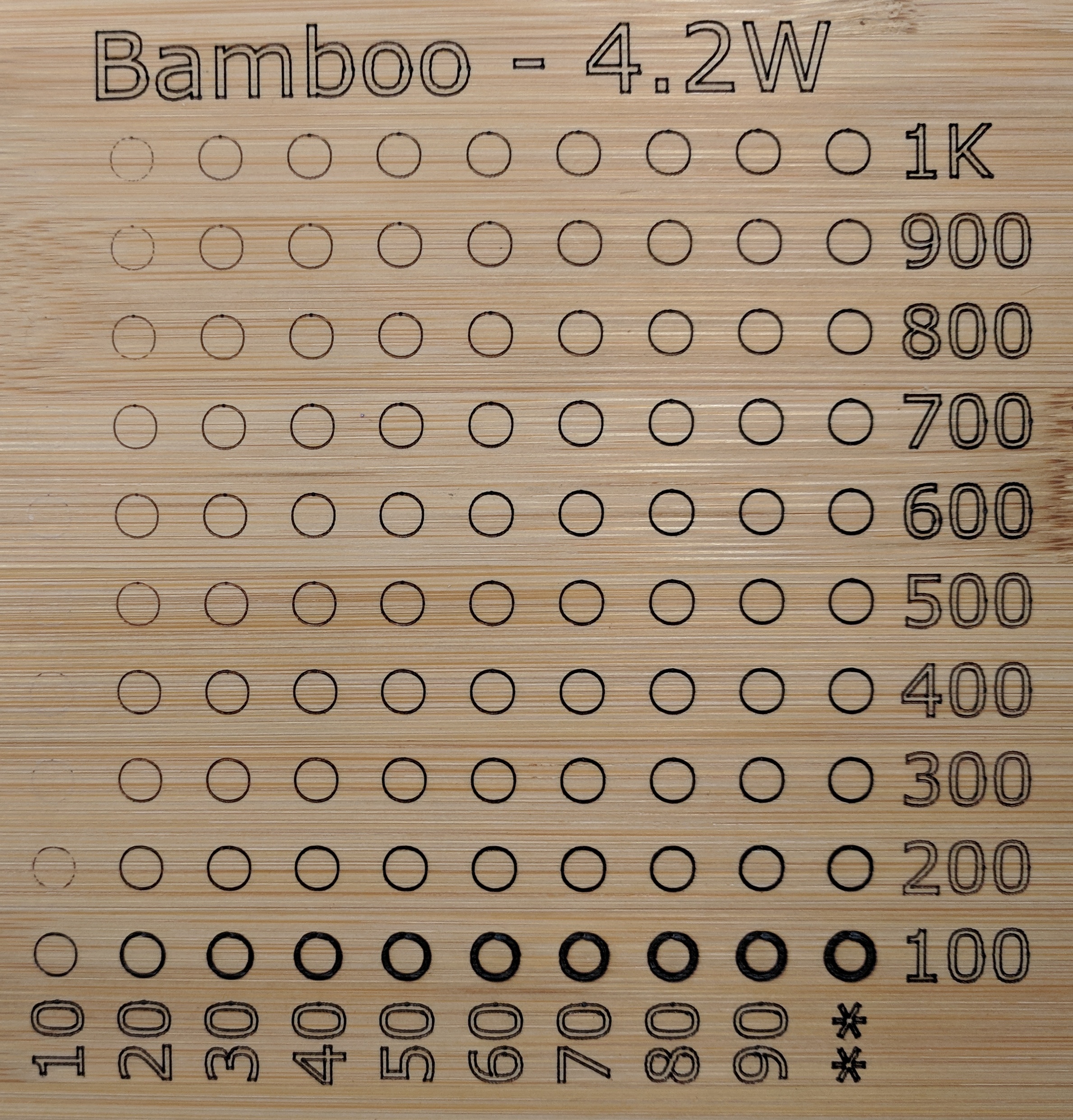
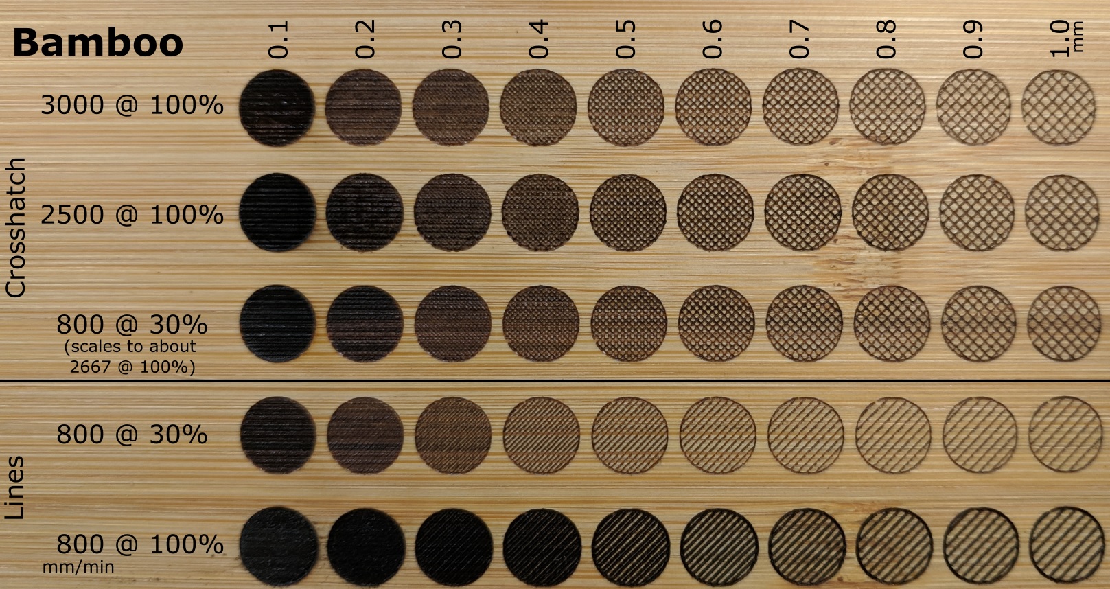
I haven’t for the power/feed demos, but that’s mainly because the circles already give me enough info. While it’s not exactly linear, looking at, say, 50% and 100%, it’s pretty easy to extrapolate what 100% power would look like at higher feeds. (I imagine some of the nonlinearity is due to char reflecting/transmitting less energy from the laser – a slower feed rate spends more time hitting already charring material.)

The other factor is that there’s a limit to how much precision you can assume in a power/feed demo chart, anyway, as the grain pattern of a piece of wood often has a much larger effect than a small change in feeds or power settings.

For engraving trails on a terrain model, I’m definitely doing a fully 3D toolpath (created by mapping SVG paths onto PNG heightmaps in my QGIS plugin). I generally have the low areas about 30mm deeper than the top, and while I may perhaps get acceptable results being 1/8" from “perfect” focus, being four times that far would likely be well into undesirable. If you’re making just a bit of smoke (and not sucking it all away before it has a chance to shine), you can easily image the shape of the beam – a narrow cone down to the focus point and then expanding beyond.

Since the as-shipped focus would definitely crash the shroud into my 3D terrain, one of the first things I did was adjust the focus to about 75mm or 3 inches from the lens. Obviously, that means more of the beam is in open air beyond the bottom of the shroud, but it also means that the included angle of the cone is narrower. The beam always starts at the width of the laser emitter, and at the focus it’s as narrow as you can get it, so the longer the distance between those, the more stretched the cone. Whether that in itself would make refocusing worthwhile is something I cannot decide, but if you need the reach, the theoretically deeper “depth of field” is a nice bit of lagniappe.

I used a carbide blank gently bottomed out in the collet to probe Z, then jogged up 16mm so I was right about 75mm, stock-to-lens. I set the focus there (using a camera screen and my best telephoto lens to really zoom in, then jogging up and down to watch the “dot” change shape – lather, rinse, repeat until good enough). Now whenever I go to use the laser, I bottom out the same piece of carbide and probe Z, then jog up 16mm. Instant known-good focus.

1 Like

Haha, this Texas transplant from the West Coast has to look that word up!! I’m honestly not too worried about how far the beam extends beyond the shroud because where I sit when CNCing I’m right at eye level with my machine bed, so the goofy glasses are pretty much mandatory all the time anyway, the shroud is mostly useless unless I’m hovering. I may buy some of those shields to put in front of the burn for that. I just did a pretty clean burn on a small piece of MDF I had kicking around at 130ipm and 80% laser, I’m impressed!!! I have some 3mm Baltic birch sheets coming tomorrow (thanks Amazon!) and I want to try cutting through. From what I’m reading this should be possible…experiments await!

Thank you again for the detailed answers (and the added vocabulary), definitely provides some clarity!

Dan

1 Like

My current project is going to involve filled shapes, so this morning I did some testing with LightBurn-generated G-code before heading to work. I generally design in Inkscape, and I’m using UGS as my sender for laser G-code. Using LightBurn as a middle step for raster-style art seems likely to become one of my use cases.

I’m not using LightBurn to actually connect to the machine and act as a sender, so all I have to do is choose “Start From: Current Position” and set a job origin, then click “Save GCode”. I then jog to the job origin and run the G-code through UGS. To me, this is a perfectly cromulent workflow, and it saves me from the annoyance of having to change machine parameters to switch back and forth from router to laser.

Anyway, the art I’m planning to burn is two-tone, so I ran a couple little test sets this morning to see what I might want to use as settings for each color. This was just a preliminary test, so I grabbed a couple settings from my earlier test matrix circles, then had LightBurn fill with lines or crosshatches of various spacings. I then took the 800/30% crosshatch and noted that it would scale linearly to 2667/100%, so I ran a set at 2500mm/min and a set at 3000mm/min, bracketing that. The results were as expected.

6 Likes

Bamboo, 4.2W.

  • Light fill:
    0.4mm crosshatch at 45°
    100% power
    3000mm/min
    (No outline)
  • Dark fill:
    0.3mm interval
    100% power
    800mm/min
    (Same for outline.)

I like how the bamboo grain shows up quite distinctly through the light fill.

6 Likes

Would it be better for your laser to reduce the speed and reduce the power?

Theoretically, it may be, but I’m not too concerned about running the laser at 4.2W. As far as I was able to fathom while researching before I bought my laser, I believe the 7W is the same emitter as the 4.2W, just driven harder, so running it at 100% of 4.2W seems acceptable to me. (I’m not sure whether the heatsink on the 7W has been updated as well.) I don’t expect to be limited by laser lifespan.

Of course, given that the laser power supply has a set current and controls effective power by PWM duty cycle, things are just a little more complicated. For example, if you compare a 4.2W laser running from a 2.5A constant-current supply with a 7W laser running from a 4A constant-current supply, dropping the 7W to 4.2W effective power would still be hitting it with 4A, just on a lower duty cycle (as opposed to 2.5A on a 100% duty cycle).

You could theoretically achieve the same effective power by dialing down the current setting of the constant current power supply and retaining the 100% duty cycle. For the 7W laser, J Tech Photonics notes, “Because it is running at 7W, the lifespan will be diminished. Running it at lower current will increase the lifespan.” Changing the current setting is done physically (in my case, swapping jumpers to select a range and twiddling a trim pot for fine control), whereas PWM is completely in code.

All that said, for hobbyist use (as opposed to running things full-tilt for three shifts a day), lifespan does not seem likely to become a limiting factor. If it does come into play, I’ll likely have made enough money off burning things to replace the module as a “wear item”, just like my collection of carbide.

2 Likes

I messed about a little more with mine last night.

7 1/2” $tar Wars Aztec calendar on Baltic birch ply:

And a tiny design on the bottom of one of my tiny wood turned tealight holders:

Dan

5 Likes

@luc.onthego You could try calling Jay at JTech to get the official lowdown as to what you can expect from running the 7W at lower power settings. He is extremely knowledgeable and seems keen to build a solid user base, so see what he has to add to the excellent info @ClayJar offered.

Don’t forget to let us know here what you find out!

1 Like

I was not planning on getting a laser in the near future but since I had read in another thread that the lasers had a useful life that depended on the their usage. Seeing that @ClayJar had done tests indicating that using the laser at lower power while slowing the surface speed gave the same results, my comment was to learn if it was something to consider.

I wanted to make some 15"x7.25" boards to use (with bingo marker discs) for a game instead of the standard paper score sheets. (I also upgraded the design from four rows to six, because why play by the original rules?) For the stock, I took a pair of 8’ 1x8 boards, planed them down to half an inch thick, and cut them to length. That gave me a dozen blanks.

I then cut all the pockets (a single 3mm deep pass with a 1/4" ball nose and 1.5mm stepover to leave just a bit of interesting texture in the bottoms). After that, I sanded the stringy bits (belt across the face, then those cheap puffball-looking sanding things on a Dremel), and then it was laserin’ time.

For the laser, I used my 4.2W at 100% power and 500mm/min. The G-code was generated from my design in Inkscape, using the J Tech Photonics laser G-code extension. The characters are from the “serif medium” typeface in Inkscape’s included Hershey text extension. (The lock icon, rectangle, and dividing slashes I made myself.)

I generated the laser gcode for everything in the pockets, then generated the laser gcode for everything on the surface. I did not include anything for the Z axis. I then edited the pocket laser file to add G0 Z-3 right after the header. I added G0 Z0 at the bottom, then copied the entire contents of the second file (except the header) and pasted it in. That left me with one bi-level file for all the laser engraving, streamlining the workflow. Each board took just over 14 minutes to burn.

5 Likes

It just occurred to me that the test piece would be an interesting example of being slightly off “perfect” focus. The top two rows of pockets were 5mm deep, and after that I adjusted things so that the rest were 3mm deep.

With my laser focused at about 3"/75mm from the lens, the 2mm difference between the surface levels does actually show up if you look very closely. The parts of the characters that are two lines wide show either two cut-in valleys with a tiny little ridge between them or one cut-in valley that’s deepest right at the center. The former would be from the laser spot being slightly smaller than the lines are apart, and the latter would be the result of the laser being slightly defocused, melding the lines.

Until I took off my glasses and took a very close look, I didn’t notice, but the difference is indeed there. (Zoom in on the zero in the “10” for the best pixels.) The standard advice for greyscale raster engraving is to operate slightly off focus to blend the lines, and this nicely illustrates the concept.

1 Like

Curious if you’ve actually tried cutting through anything with yours? I tried some 3mm birch plywood and no-go so far, but it may be my settings. Also curious if you’ve looked into any air assist? The problem I think I’m having for cutting is that the cut gets filled with charred junk, then the laser can’t really hit the uncut material. After a few passes I’m nearly through, then it just burns and gets wider with burnt stuff. I tried both the high efficiency and the high resolution lens. The high efficiency lens is supposed to put down more power, but the beam is wider so the char is worse. I’m wondering if using as simple as an aquarium pump would kick enough junk out to keep cutting? Tried messaging JTech on FB Messenger last night, but so far no reply.

Dan

Regarding air assist, I haven’t looked into blowing on the cut, but my SmokeSucker (custom dust boot analogue for smoke extraction) might actually be doing effectively that, just the other way around. There’s quite a strong airflow across the cut, as the vacuum whips the smoke away (with little sparkling embers sometimes, depending on material and settings).

I’ve not tried cutting through wood. (Corrugated cardboard worked well with a couple passes.) I really should try so I can test whether the SmokeSucker has an effect on deep cutting.

1 Like

I didn’t end up going with the jtech on my shapeoko, I bought a Chinese 40w CO2 laser… for information though, an air assist changes the performance hugely… without air assist I couldn’t cut through 3mm ply, with air assist I can get through 12mm…

I don’t have a permanent fixture yet, but run a line off your air compressor, through a 1/16 to 1/8 nozzle and direct it at the point that the laser hits, from as close to vertical as you can. For any more info just Google ‘k40 laser air assist’ it’s pretty well covered

3 Likes