I’m trying to work with some aluminum pieces which measure 6"x10". I also will be working with 8"x14" and even larger sizes. I have the pieces cut out on a table saw so they’re imperfect and need a finishing pass around the sides to make them perfect. After that I’d like to add a chamfer to all sides.
The first issue I’m facing is that I need to place the pieces down and secure them at a perfect angle to machine them accurately. The sides are imperfect so how can I do this?
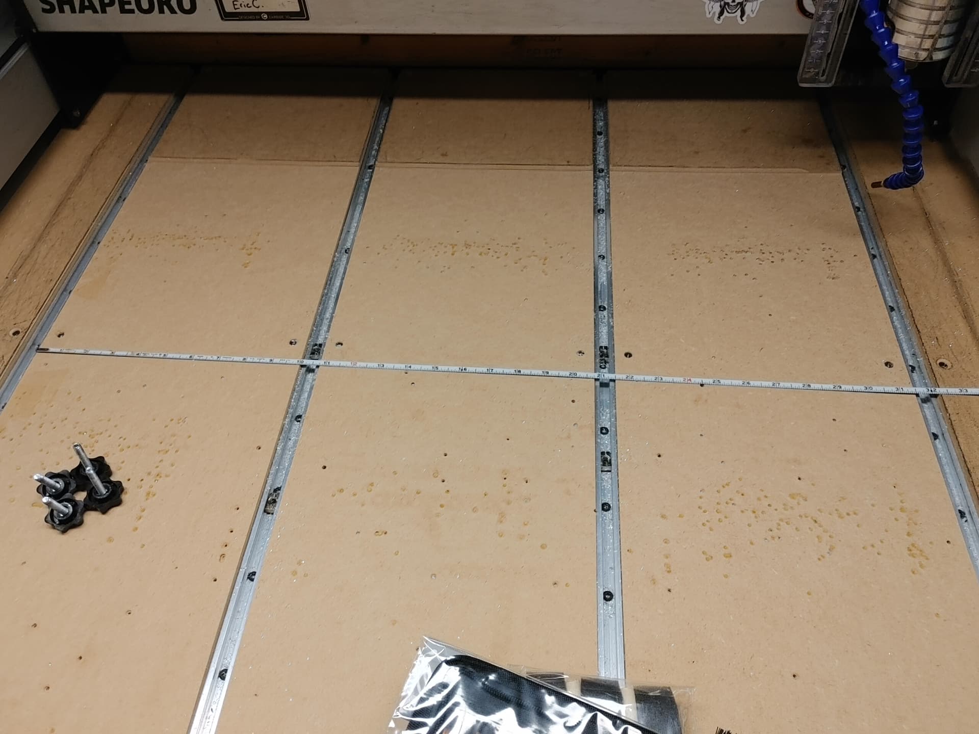
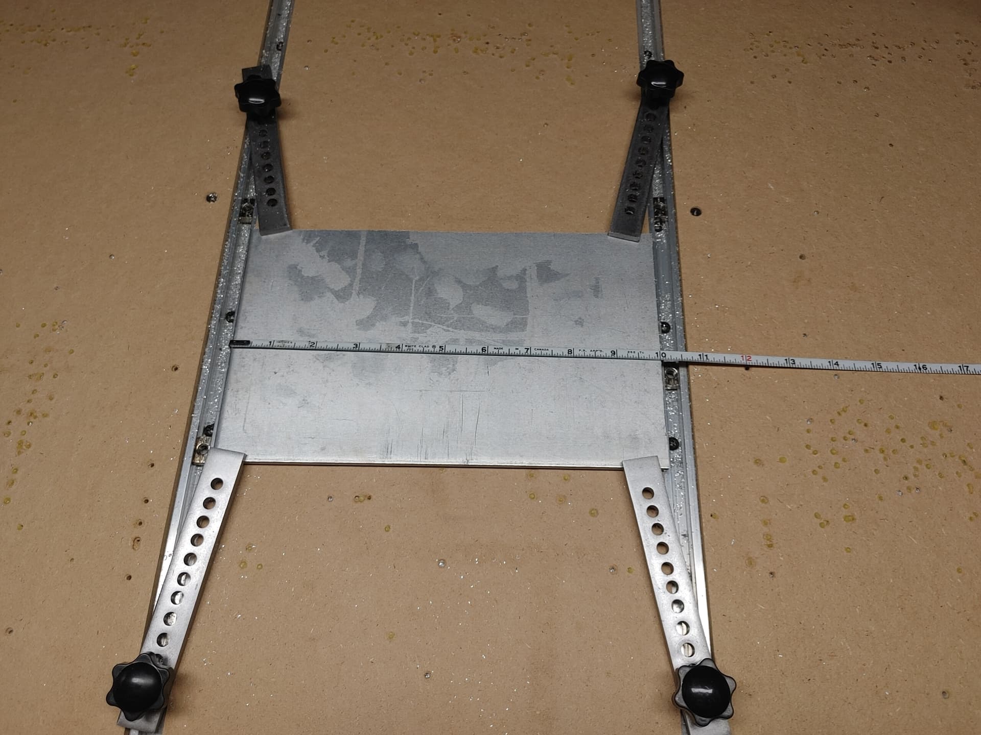
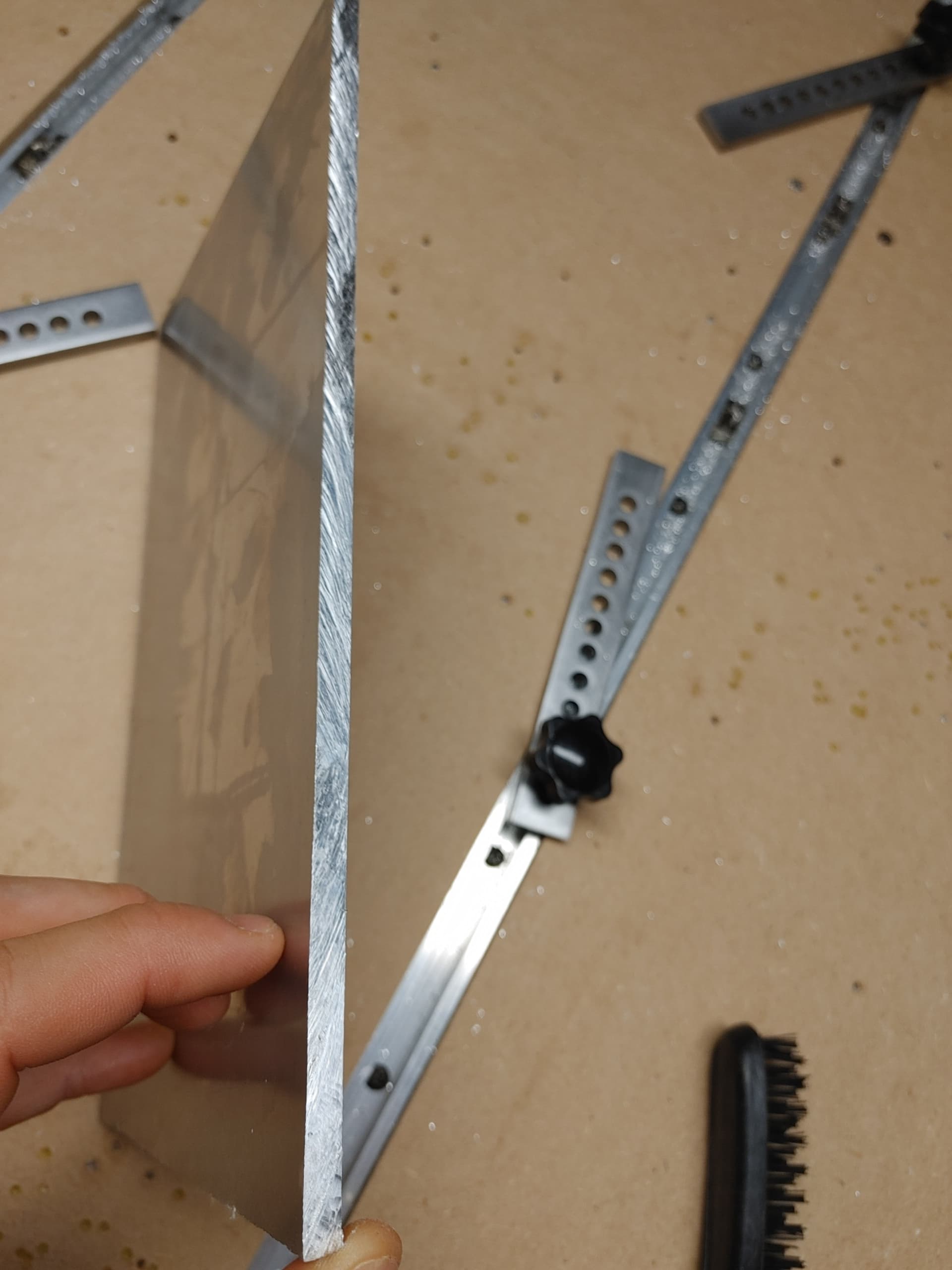
The second issue is fixturing them down securely. This is my current setup (pics attached). The clamps get in the way of the process. Should I use the super glue and tape method directly on the wasteboard? Should I make an aluminum wasteboard (slightly larger than my project piece) and secure it to that?
How many pieces at one time? And how often?
Are you concerned about how long it takes to switch parts?
How accurate does the chamfer need to be?
How much stock did you leave to get to your final 6 x 10 size?
An aluminum fixture would be cost justified if you are doing enough of these.
2-way tape (or tape-glue-tape) works well for small quantities.
I wouldn’t tape directly to MDF though. You’ll end up ripping chunks of MDF up.
Use a sacrificial waste board if this is the case.
FYI, When you use hold down clamps, you want the screws as close to the workpiece as possible.
You are getting very little leverage in that picture above.
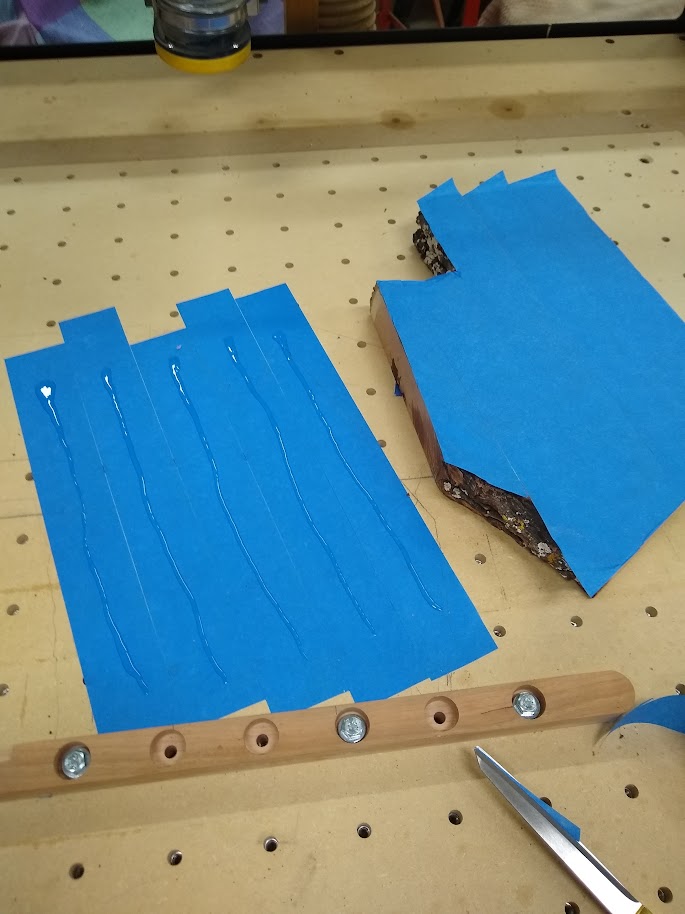
Painters tape and super glue. That would hold them securely and let you remove the clamps in the way of machining them. I use the regular 3M 2" painters tape and TiteBond Medium CA glue. Never failed. You place the tape on the spoilboard. Then place the tape on the back of the alum. Make sure you match the lines of the tape to the material. I spread an S pattern of super glue on the spoilboard tape on each line of painters tape and press the material down and wait about 5 minutes. Light clamping helps to bond the CA to the tape. When done just pry up the tape on the spoilboard and remove the two layers from the back of the material.
Here is an example of an odd shaped piece but it had a square bottom.
Is there any custom fixture I could build outside of a vacuum table that would hold down the workpiece without super glue and allow the endmill to pass fully around all sides?
Not that I can imagine. You could make a fixture that cuts 2 sides at once, then move the clamps to get the other 2 sides.
A cutter that side cuts like an end mill, but also has a chamfer like a mill-drill would allow you to cut the profile & chamfer in one setup. The fixture would have to be open on the edges to allow the cutter to pass below the edge of the part.
So for your 6x10 piece, say you have 0.1" extra stock, so 6.1 x 10.1. 0.050" stock all the way around.
Make a fixture that is 5.950 x 9.950, with a fence on the front & left side. Cut a scrap piece of something rigid to use as a hold down on top of your workpiece a little bit smaller, say 5 x 9, and clamp that from the front & left.
Make a contour path that cuts the right & back edges down to 6.050 x 10.050.
THen flip the part 180° and use another path the cuts it to the finished 6.0 x 10.0.
Does the part in question have consistently placed holes?
If so, clamp, set origin, machine holes, then remove clamps and secure in a fixture which has threaded inserts to match the holes using the threaded inserts and suitable hardware (I use nylon or aluminum if I’m not absolutely certain of the endmill being kept far away from it).
Do you have any holes or slots that you could place a threaded insert under? If so you could do a first cut that just cuts those inner features while side clamped. Then put the inner bolts in, remove the side clamps, and cut the exterior features. Sounds like a lot of work, but I’ve done it a few times and it works well.
I like the suggestion and want to make a fence, it seems like a really nice setup. My question is though assuming all sides are imperfect how could I lay the piece onto the fence and expect accurate results?
I’m currently cutting aluminum with a crappy dewalt 20 tooth framing blade. It’s not terrible but not great either. I just got in a proper 80 tooth aluminum blade so hopefully it will make my cuts nicer and eliminate some of the problems I’ve made for myself
That’s a great idea. It will often have holes, but may not as well. It depends on customer demand (they may prefer fastener delete) and I haven’t fully tested the market.
I plan to add some threaded inserts to the table, waiting for them to arrive.
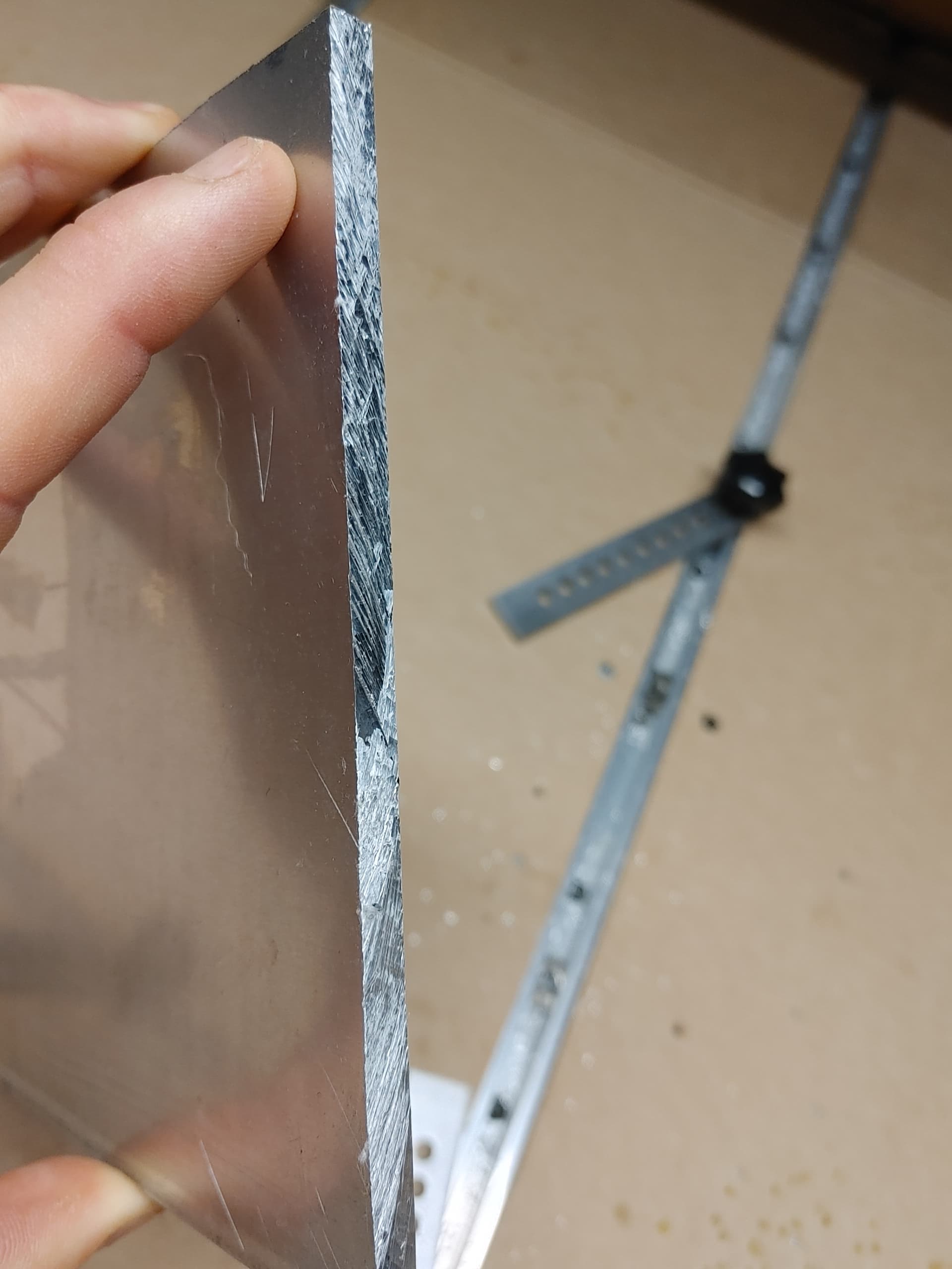
Not too bad. I’ll include some pics. They don’t tell the full story though. If I hold up a straight edge to it there will be small bumps and valleys around 1mm. That could throw things off I think. Generally it’s just a bit messy and needs a cleaning. My aluminum plate originally got cut by a plasma cutter to fit it in my car and those sides are the worst (not pictured).
I find the idea of a router with template very interesting. I don’t have any idea how it would work but I’ll research it. Sounds like a promising solution.
Yea that’s not too bad of a process even if its a bit time consuming I’d be ok doing that if needed. I’m concerned about larger size projects too though, if they only have a couple holes it will be an issue. Generally there will either be 0, 2 or 4 holes.
I made the assumption that it is geometrically possible to machine the part & still get a 6x10 finished piece from it. i.e. it is close enough to square & has enough extra stock around the edges.
If the edge has 1mm of variation, then the part should be at least 2mm larger than the finished size if it’s square. A bit more if it’s not very close to square.
You have 4 corners that will fit into the fences. Flip it around for the best fit and adjust the cuts to take off just enough stock to clean up the first two side. Once those sides are flat & square you flip it around & it should fit snuggly into the fixture.
Started scrolling through one of the books and it really made me want to buy a low profile machinist vice and a 1/2" steel palette with screw and rod insert points
I could make my own 1/2" steel palette for relatively cheap. Strongly considering it. It just wouldn’t be accurate to a high level and also I have no easy way to surface it. Really looking forward to makng that one day though!
At first I couldn’t quite wrap my head around it, but I played around with a mockup in photoshop and what you’re saying makes perfect sense to me now. Leave some excess, trim the sides opposite the fence to get a perfect 90, then once flipped, trim again for another perfect 90. This seems like a really good solution!
What do you guys think of this idea? I was looking into router templates for 5 minutes and thought up this table / fence system:
I could run my sides of the workpiece along the fence and it would trim off small amounts of material, and potentially do the chamfers this way as well.
Interested in feedback, especially critiques and downsides. In my mind it actually wont work. Because there are inaccuracies in the work piece when I trim each side individually it won’t end up perfectly square.
You would want to use a 6.000 x 10.000 template with the router table, and a follow bearing on the router bit. Make the template on your cnc machine. You don’t really need the fence on a router table when using a template, but it is a nice safety feature that gives you something to rest the edge of the part while feeding into the blade.
I learned a lot about routers and this seems like something I’ll be moving forward with. Just need suggestions on a couple of things:
Router / spindle. I could buy another dewalt router like what’s on my shapeoko 3 but the RPMs seem a bit unideal. Not sure if I should choose something else. There are bigger 2hp routers for only $100 more, I’ll have to double check they’re variable speed. Also I have a 2.2kw spindle I could potentially use.
I have a spare table saw table I could convert to a router table.
What kind of bits do you suggest for my application? I’ll always be working with 1/4" aluminum and 1/4" acrylic for the template. I know I need something with a bearing but other than that it seems like there’s quite a few options.
The Dewalt router is a 69MM diameter. As far as I know there are no 69MM 2 HP routers. You could buy a different router mount if they are still available for the SO3. That is dependent on if you have a Z-Plus or an HDZ. The original SO3 router mount came with an adapter for a 66MM (Makita/C3D Routers). They do sell an 80MM mount for larger spindles but those are not recommended for a Z-Plus. The HDZ can handle an 80MM spindle. That is not to say they would not work but an 80MM spindle is quite heavy compared to a trim router it was designed for. They do make 66MM air cooled and water cooled spindles.
Just make sure you can get the right router mount before you buy a new router/spindle.