i just finished building the machine, but the touch probe can’t get a closed loop, and I need some help:
I have PCB version 2.2 from 2015
touch probe 3 wires (white, green, red) are properly connected to the PCB
touch probe has the green LED active
Problem: My PCB has no ground connection to the chassis. the PCB is fixed with 4 nylon screws to the base, and the PCB has no copper traces where the screws are. hence the touch probe can not establish a ground loop.
in other words, I found plenty of places on the chassis to attach the ground alligator clip to, but the chassis has zero connection to anything on the PCB.
question: where do I connect the ground loop to the PCB in order to get the touch probe working?
When you touch the crocodile clip to the touch probe (the bitzero?) does the light go red?
If it’s the bitzero you have then the idea is to ground the cutter in the collet with the croc clip and then when that touches the bitzero the connection is detected.
Normally the router spindle is insulated from the machine frame anyway.
Correct, when I connect the clamp to the touch probe, it doesn’t go from red to green because there is no path… any advise where to patch ground from the PCB to the chassis?
The base plate (heat sink) is beautifully grounded connected to the rest of the machine.
but nothing on the PCB is connected to it, there may be some kapton tape underneath that would isolate everything very well.
ground on the PCB itself is also inconsistent, as the metal housing of the USB plug isn’t connected to any other ground (i.e. the 5V/GND pad on the upper left, or the big fat 4-pin pads on the far bottom right…
It doesn’t matter much, I just need to find the single magic GND pad on the PCB that would be working… any ideas?
This board is a bit older than anything I’ve dealt with, I think we need somebody who knows the older machines, @WillAdams perhaps?
As for the USB housing, on the later boards that is isolated from the PSU ground to help with interference so that seems to be the case for you too.
If you’ve got continuity between the earth pin on the PSU brick and ground on the board then you could just wire to any mains earth.
It would be much better to find a supported suggestion for where to ground though, one of the carbide folks or the support team should have a better idea.
Unfortunately, the electronics mystify me — I had Radio Fun. in the Air Force and that was it (I had aced the ASVAB, EDPT, and DLPT and had my pick of specialties and chose to be a linguist and get a year in California at the Presidio of Monterey — it seemed like a sensible choice at the time).
When I did a Probe it was on a 2.1 board, and I was just completing the circuit for the Probe connector, not going to ground.
I’ve escalated this ticket to folks who do understand the electronics and hopefully @Jorge or someone else will chime in.
It is possible that your lead is broken. Have you checked the continuity of the long lead that attaches to the router spindle to the other end of t he wire, which for me was a round connector. As others have said above most of the boards have a big alum heat sink that is touching the frame of the Shapeoko. I have an XXL and used one of the bolts in the left Y rail to attach to my machine.
Double check that you have a complete circuit from the attachment point to the alligator clip. I have seen some early model BitZero’s have a wire crushed on the bottom of the cover that kept the thing from working, but I also remember they got no green led. If you have some wire available strip the two ends and hold one end on the frame and touch the BitZero to see if you get the red led. If you get no red led when using the wire then you may have a ground issue. But I would put my money on t he alligator clip lead not having connectivity, i.e. broken wire.
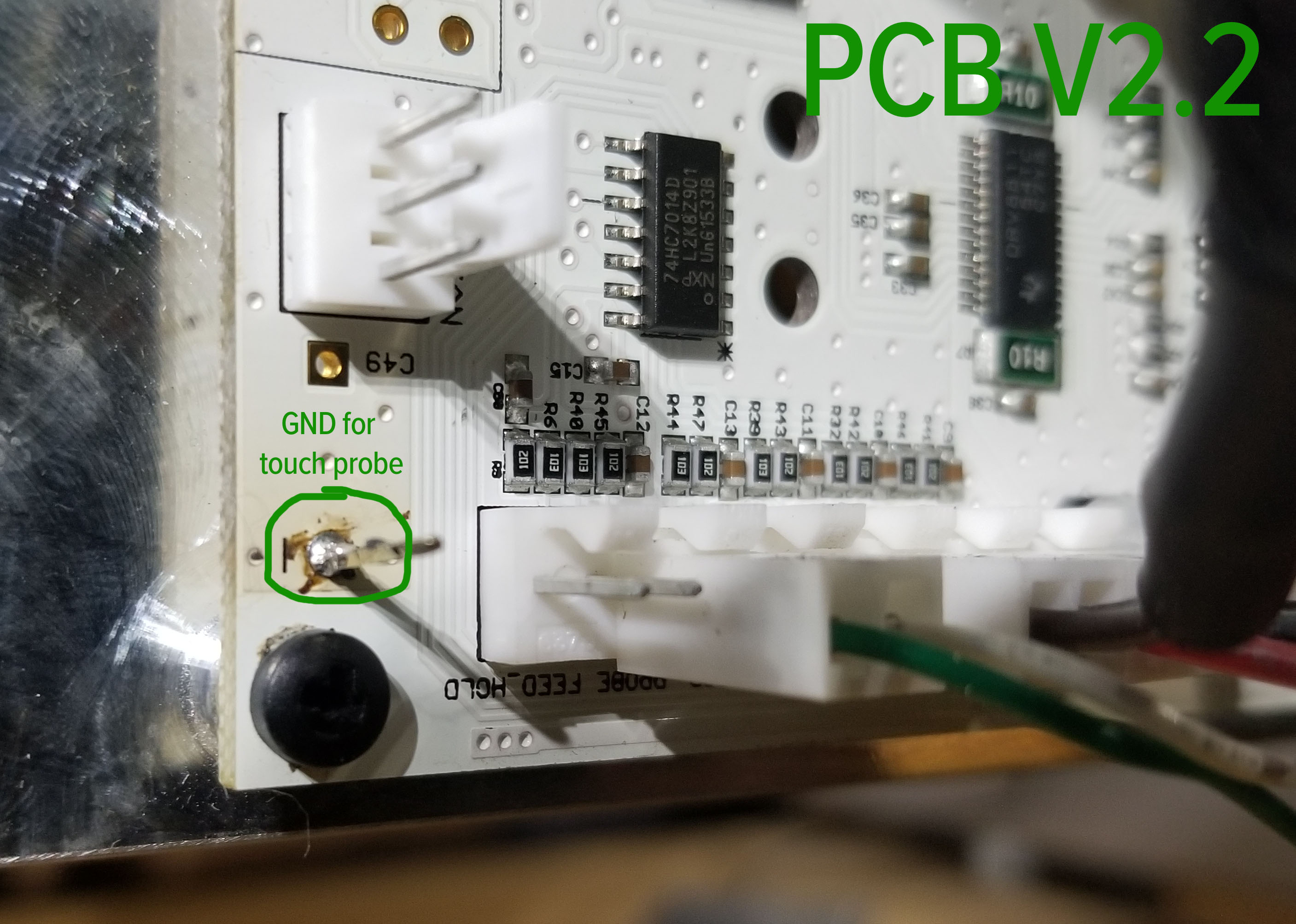
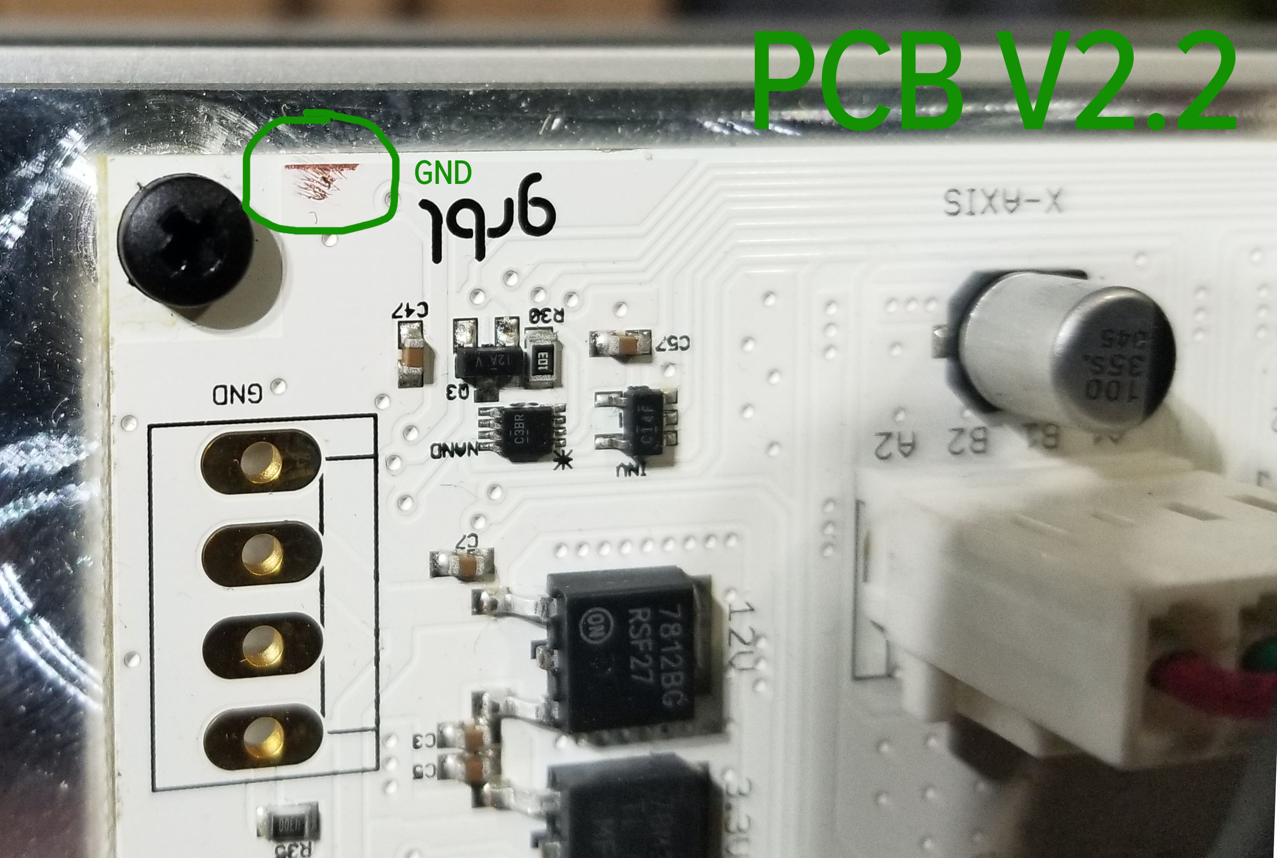
i started to scrape away some of the paint on top of what appears to be the solid GND trace on the PCB (lower left corner of the 2.2 PCB), and that closed the touch probe circuit nicely (red LED goes on when touching the pad).
I did find a working pad that is also connected to the GND plane, and soldered a pin in where the ground to alligator clamp will connect. now the touch probe is nicely working as it should (I am also trying to win a price for the ugliest solder job of the week)
I did not connect the PCB GND to the chassis GND. I am uncertain if that would cause additional problems (although it shouldn’t) (see USB comment above) or make things easy, so I left it alone, and just created the GND for the touch probe.
I am sure a similar procedure could be done on other boards that have similar issues.
Hi Will, thanks for your reply here. I had tried emailing support and sales over the last week or so, and I have run into kinda not so great things (ordered an endstop kit, got 4 end stops and had to design/print my own endstop holders), hence me reaching out to the community here.