I don’t know that is need to be adjustable for height, but when I remake these in alum, I will add about 1" (25mm).
I really don’t want to start to thinker too much with this machine. I just want it to run.
I don’t know that is need to be adjustable for height, but when I remake these in alum, I will add about 1" (25mm).
I really don’t want to start to thinker too much with this machine. I just want it to run.
I love my Shapeoko but I was also disappointed with the Standard S3 frame compared to the XXL. No center support , just mounting to MDF was kind of a shock. I would like to upgrade to 80/20 also!
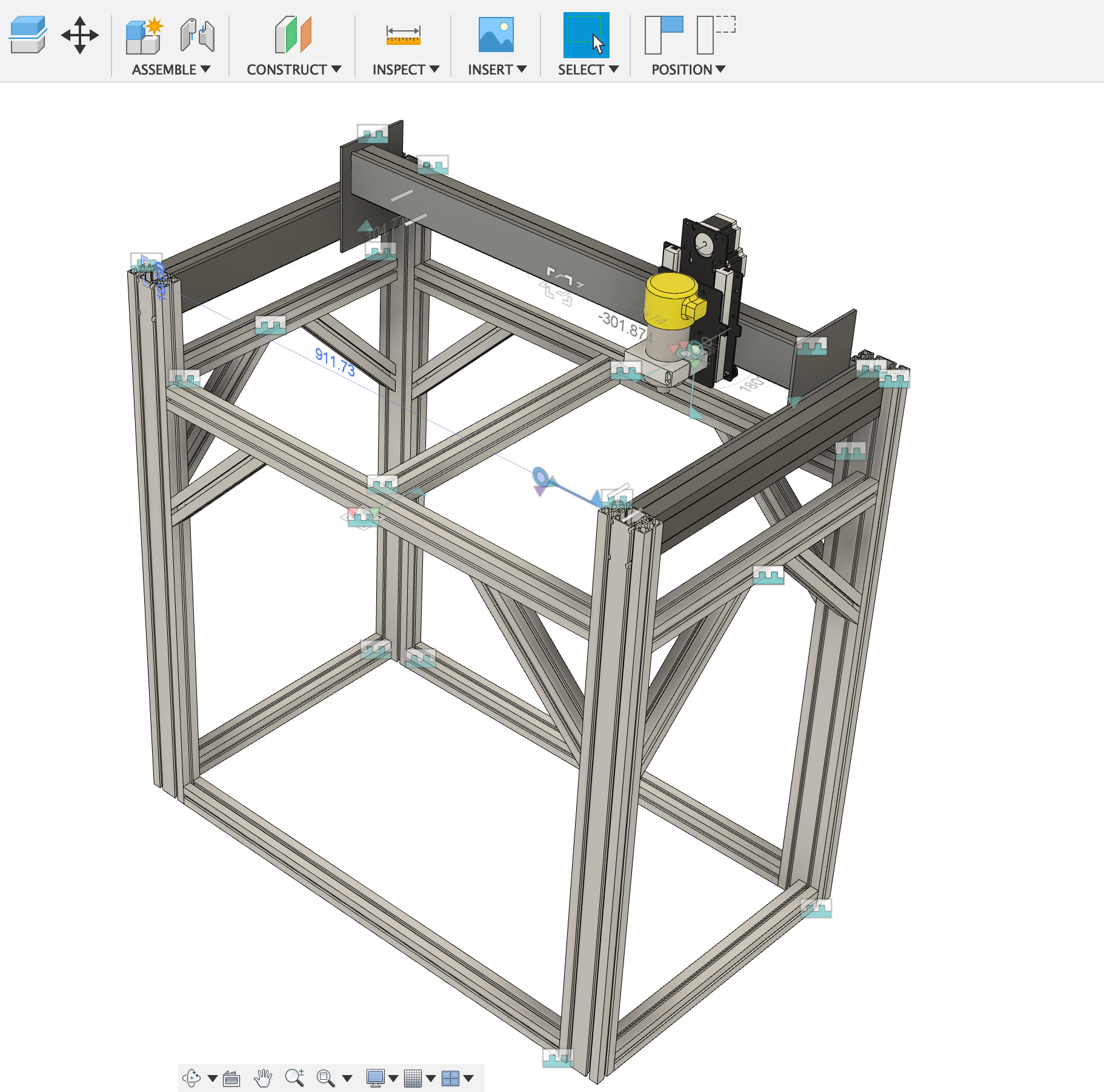
I was inspired by your extruded aluminium table/frame idea. There is a company in my city that produces and sells this stuff, so I figured I’d work up a design. They will mill and counterbore the supports for a couple dollars a hole; that way I can directly attach the SO3 Rails. Far from finished, but this is what I got, I’m willing to share all of the files and links if it gives anyone good ideas!
should have added make the bed height adjustable… but this design would in theory let me raise and drop the bed as needed.
If you have not yet ordered the set up consider the height. I am older and like to sit in an office chair and baby sit my Shapeoko. Some like to stand and work. My table is 29 inches off the floor to the top of my stand. Also you should include casters that lock in both directions. It is nice to move the machine for cleaning or in my case I can roll it out side under my covered patio in warm weather.
You design looks good. As with any thing a strong foundation is important.
I will note that extrusions were used for the SO2, and for early prototypes of the SO3 (going from memory of photos which @edwardrford showed) — while I love the flexibility of the extrusions, the loss in rigidity is tough to bear.
Have you considered incorporating your endplates as stiffening brackets? And I’d at least double up on the cross members under the cutting area.
Also, how are you going to handle belt anchoring? I’ve always been surprised that there isn’t some industrial standard mechanism for this which is used to secure them (there have been a bunch of different systems for it). If I had an extrusion end such as you show I’d design a mechanism for belt anchoring/tensioning which could set on the top of the extrusion and be hidden by a cap when not in use (maybe w/ a tiny window which a bit of belt to which some green paint had been applied after tensioning would show) — that way there’d be a visual indicator if something slipped.
That’s good to know, I personally had excellent luck with rigidity in extruded aluminium, provided proper connectors, and stiffeners. Do you by any chance remember what the specific issues were ?
Yes, there’s a handful of stiffening components that I haven’t added to the model yet. I’ve been going back and forth with the company to determine the best components. Are you suggesting I move from a single center support to two supports, or from a single double width extrusion?
Right now I’m at 40" to top of work surface, I’ve bounced around between 36"(normal counter height), and 40" the height of all my existing work benches. I was considering a bar stool style chair if I needed to sit for a while. And yes the company has a caster / leveling foot combo that could do the trick, sadly a set of four would have taken a bite out of my HDZ budget, So I’m opting for a leveling foot with a wide base.
![]() That’s a secret for another post… I actually have an old Objet30 3D printer in my basement. They use Gates style belts and have an amazing system for both tensioning, and indicating tension. Reverse engineering it and posting the CAD files up here is somewhere on my to do list. I will be integrating them into the design at some point.
That’s a secret for another post… I actually have an old Objet30 3D printer in my basement. They use Gates style belts and have an amazing system for both tensioning, and indicating tension. Reverse engineering it and posting the CAD files up here is somewhere on my to do list. I will be integrating them into the design at some point. ![]()
Please keep the comments coming and if there’s interest I’ll start a new thread as I continue the design.
Add one for two supports — far stiffer to divide a span into three sections than two.
Hi folks, I am happy to read some good comments on there and that I was able to inspire some of you. After all that is the great thing about these forums.
The extrusion I am using (8020) are great and strong (but they are not an inexpensive system by any means - but you get what you pay for - sometimes…
When it comes to the SO3, most of the folks who are making accurate parts that done something to the base of the machine, and as @gdon_2003 mentioned you need a strong foundation if you want to be successful with any machine. I am a little disappointed at the frame of the SO machines. It is a recipe for failure and I can’t imagine the frustration of users new to CNC who can’t figure out why they parts aren’t cutting well. Forget about cutting anything other then foam accurately.
@TheSilentEngineer, I have some comments on your frame. I would things a little different (as you see my table is a bit different)
1- You need leveling feet or a means to level the table. some folks think that is it okay to have only the machine level. - nope. everything needs to be even.
2- This is more a question, but how to you plan to attach the SO extrusion to the 80/20. 80/20 can only be bored and milled in certain areas. I suggest that you design an interface plate or some sort.
3- I also think that for the weight of the machine your frame is overbuilt and you can value engineer some of the braces. You just don’t need that many. (to fund your HDZ) ![]()
4- Yes to take this opportunity like I am, to add more support under your spoil board. (one center two sides for an regular SO) (I am doing this today)
This depend on what type of extrusion you are talking about. The stuff I have used or what my larger machine was made of (8020) is very heavy stuff. Makes slide or the SO extrusion on the other hand not so much… But I do like that the “linear rails” are part of the extrusion. The v-wheels are alway going to be the weakest link especially on the XL and XXL models. Which explains why many of the more experienced folks are going to hi-win type rails o the SOs - I still you like to that on the grantry.
why don’t you guys design some sort of ratcheting system for the temp tension. @Luke
Going back to my project,
I made some adjustment to the bracket I printed to allow me to slide and extend the baseboard a bit.
I plan to finish the underside of the machine this week with the extrusion I have on hand and then order the correct kit (parts machines and cut to size). I also want to work on the enclosure design a little.
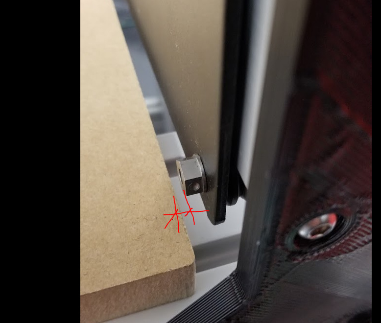
I want to caution folks: ![]()
The SO3 3d model that is floating around on BIM360 show a wasted board that is 1/2" (12mm) Thick, whereas what I receive id a 3/4" (19mm) thick board. I could no figured out why everything fit in the
model but in real life.
BIM360 model before correction:
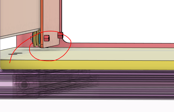
BIM360 model after correction:
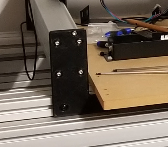
This is what I encounter after installing my brackets (Risers)
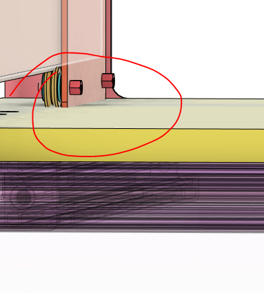
So I had to reduce my baseboard (I turned it 90 deg). I don’t think this is a bad thing because I will know that whatever stock I put in the machine will be good as long as it rest on top/inside my base board. ![]()
agreed 200%
@WillAdams, why doesn’t carbide address this so we don’t have to? - honestly it is something very basic. I was turned off a little when I learned the engineers at carbide pretended that wasteboard on the SO3 would not sag and be an adequate substrate as is with not support and spanning as is does.
Still working on that… I want to attach the table in such a way that I can lower/raise it AND still keep it
flat.
Mill in screw locations, its a couple of dollars a hole and they can hold reasonably good tolerances.
The extrusion cross section works out well with the hole locations in the maker rail, but I have
considered a plate as well.
So true, I started with a design that they provide for optical tables and machine bases. The trick is
trading rigidity as @WillAdams pointed out, for cost. I’m sitting around $650 with all milled
Do you have a picture of your added support, or the spacing you’re using? I’d love to know how it
works out.
Keep in mind that for a lot of us, things like linear rails and extrusion based frames are just fun projects. Honestly I felt the same way you did at first about the sheet metal frame, but I didn’t have your resources. I stuck it out, and I’m kinda glad I did, there was a lot of fidgeting to get the thing squared and trammed in. In the end though you can do some incredible things with a machine that’s under the $3K mark look at @Vince.Fab and the early stuff he posted on here Hardcore Aluminum milling on an S3. Some awesome work from what was a mostly stock machine.
It’s just a trade off between the time to set up , cost of the machine, and toolpath layout. This is a cheaper option for a machine, but with proper time investment and good toolpathing it can do a lot.
That said I’m totally behind modifying the SO3 you have, keep up the good work, and keep posting build pics!
The spacing for the spanning member is approx 260 mm - 280 mm which I think it is more then enough for a 3/4" table top for my machine which is half the width of yours. So you should be adding an extrusion to each half of your table.
I know 8020 get pricey very quickly, but its the best. Again as far as rigidity I don’t have any concerns, at least not if the proper extrusion size is selected.
I also want to add for anyone else who comes here looking for information.
Neither of those machine you mention are bone stock and those users also very in tune with feeds and how not to upset the machine while working with metal.
A person getting this as their first machine would not we able to go any of that, at least not with those results and would end up doing little things like we are in order to improve the hardware and rule that our from the equation.
I was working on a similar design to fit inside my 80/20 enclosures, just a base frame, not a stand.
I was planning to mill half inch aluminum plate for the front and back to mount the rails and on the bottom mount them to a square 80/20 frame with 3 center supports and 4 small outside corner brackets for hd leveling feet. I was planning on just drilling a countersunk hole through the half inch plate and use the stock clamp for the belts.
I pictured some extra brackets and some loc tite it should be better then the bent 1/8 steel attached to MDF for the base anyway and I will be able to attach a Ohio Diesel alum spoilboard more securely. Currently the standard S3 has 8 bolts attaching the 2 aluminum plates… Not very secure.
Edited my post for correctness, I was referring to his first couple of posts when he just had an HDZ. Also there are quite a bunch of other people like Winston that have done excellent work. Like you said though, it’s just a matter of knowing your machine as well as speeds and feeds, and that learning takes time.
This topic was automatically closed 30 days after the last reply. New replies are no longer allowed.