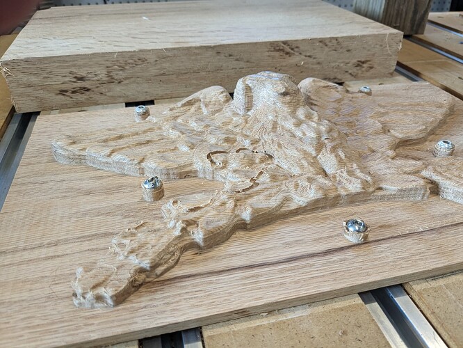
This is my forth attempt, that ended eerily similar to two other ( one made it, but screwed up the data).
This was laser scanned and it all looked good until it didn’t.
You’re doing great! I can’t even make a tray. ![]()
Can you make your fifth attempt self igniting? I believe you would then be onto something great. ![]()
LOL I believe the self-igniting ones generally occur when you leave the machine unattended. ![]()
I’ve had zero success with the 3D projects and am holding out for software and training enhancements to come down to my level of ability to understand them.
What software have you tried?
Just CC so far.
3D is just if interest so far, I don’t know that I ‘need’ to know it, but I keep thinking of how it could enhance some of the things I’m doing or may do. I haven’t put real pressure on myself to make it a priority, so it’s on me.
OK, I see. No worries, you can always ask later. ![]()
Ditch the screws (looks like you hit one) and use tape/ca glue.
Just my opinion, but i think 3D in CC is extremely confusing. I’ve gotten much better success using other programs, i gave up on CC after a month and have been using Vcarve Pro ever since, it’s a much better program, in my opinion.
CC is great for free and it’s great they provide it. But there are better dedicated programs for CNC (again, my own opinion).
Feel free to share the files and some of us can take a peek as see if we see anything wrong with them.
Looks like you maybe had some slippage, could be bit in the collet, or running into something (like the screw) that causes the machine to lose it’s position.
What machine are you using, you didn’t mention?
I have a Mac, so VCarve isn’t an option for me, but I agree with you that the 3D setup and design in CC are not intuitive and there isn’t actual training or user guide on what it does offer.
Not currently a priority for me, but at times frustrating it’s not easier to understand - I share some responsibility in that.
I have a 2 x 4 Pro 5. I use Fusion 360 for the toolpaths.
I did crash into the screw head, which was avoidable if I wasn’t lazy and ASSuming.
The stock is two 1" thick milled red oak boards
I did use tape/glue initially until I got to 1/2" of remaining thickness. I have had issues with the boards warping, so I had added the mtg screws,
First mistake was that I forgot to center the mtg screws correctly, so I had to pull up the tape, move the board 1/16 or so to align with the T tracks.
I had added the mtg holes after I was 1" into the depth. I went a 1/2" deep and should have gone 3/4" deep ( to a 1/4" remaining material). I used button socket head screws and not flat socket head screws. I should have opened the counter bores up anyway to provide clearance for the flatheads.
The crash was on the finish pass using a 3D ramp operation ( 9 hrs into a 11.5 hr run ).
A rapid move clipped the screw head.
I have since found out that the 3D ramp does not use a Avoid Surface option.
https://help.autodesk.com/view/fusion360/ENU/?guid=GUIDFCF0C83A-507A-48E3-9F08-15F104B20CBF
I had an opportunity before I started the finish path to mill the post down and replace the screws. I had visually reviewed the simulation in Fusion and thought “good enough”. NOT !!!
I am very comfortable with 3D CAD models, but the realities for CAM processing requires a level of detail planning I am learning ( the hard way at times ). All good.
I laser scanned this piece and previous attempts either had crashes for other reasons or I simplified the geometry to a point that the details were lost.
This one was looking great.
Next attempt is after I fix an electric kiddy car. Damn intermittent switches.
Vcarve Pro allows you to define “Keep out” zones to avoid the screws, clamps, etc….
I used it once but weirdly the keep out zones are defined on both sides of a 2 sided project. On one side I was drilling holes for pins and on the other side I wanted to protect those pins from the router (technically vice versa) but the zones applied to the first side as well so I had to ditch them or it wouldn’t let me save my toolpath.
The problem for me was realizing that I wasn’t building actual 3D objects. I was using the tools in the 3D modeler to create a heightmap image. So it’s a bit of a cross between 3D modeling & advanced image editing.
Once you accept the results the current model is stored as a 2D heightmap, which is why they are not parametric & can’t be edited. If you make a mistake you have to delete & recreate the components.
Did you have a look at: 3D Modeling from 2D Geometry | Design into 3D ?
Note that this dichotomy is discussed at:
This topic was automatically closed after 30 days. New replies are no longer allowed.
