There used to be, in earlier versions of CC. But it’s gone in latest versions (not sure when/if it will be reinstated)
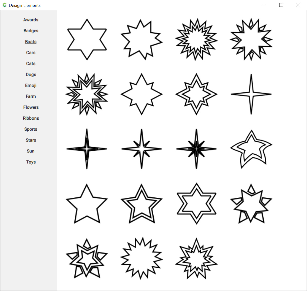
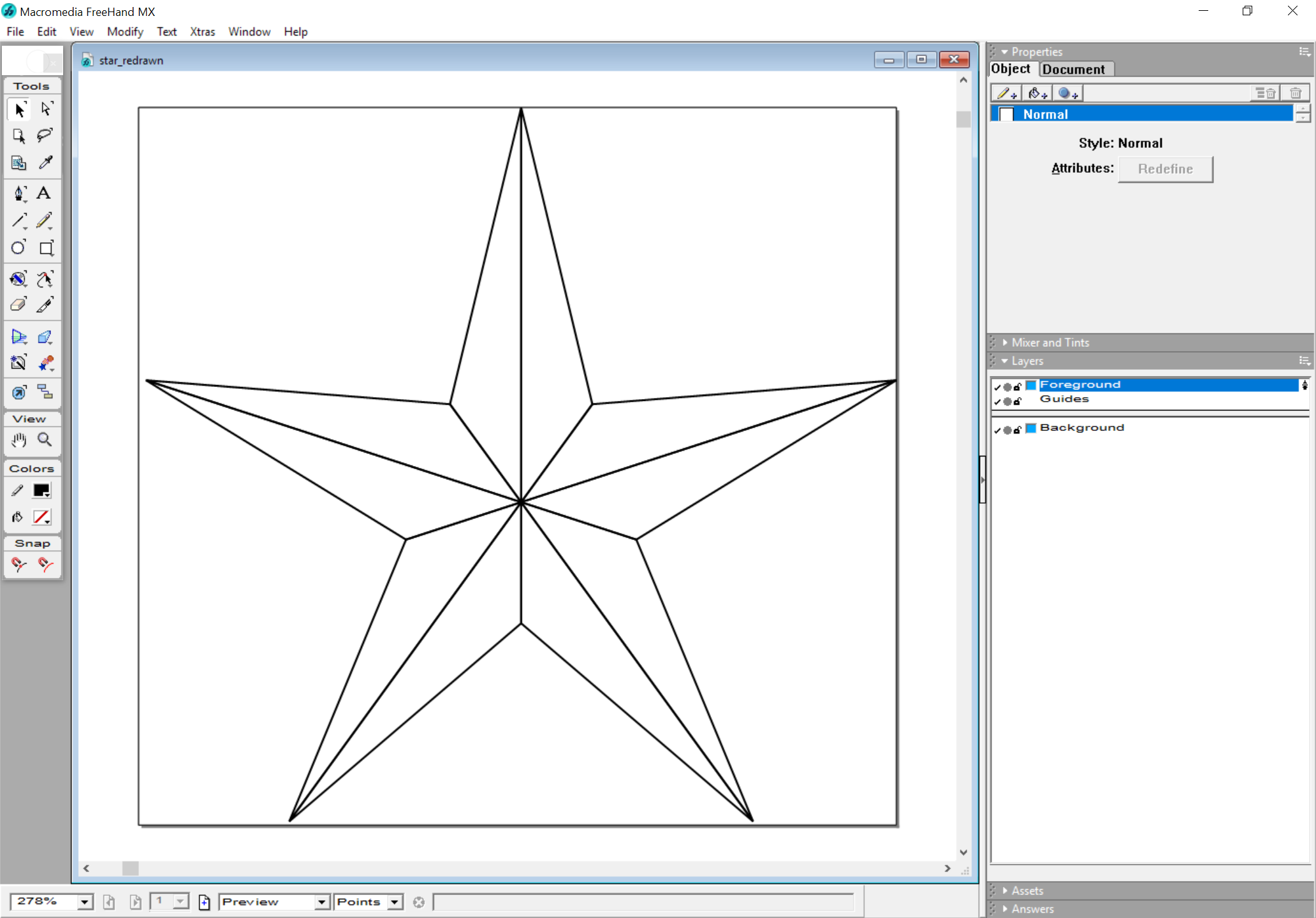
In the meantime you could probably find a suitable vector of a star online (search for SVG files), or use a vector drawing program like Inkscape to draw it, then export it as SVG and import that in CC.
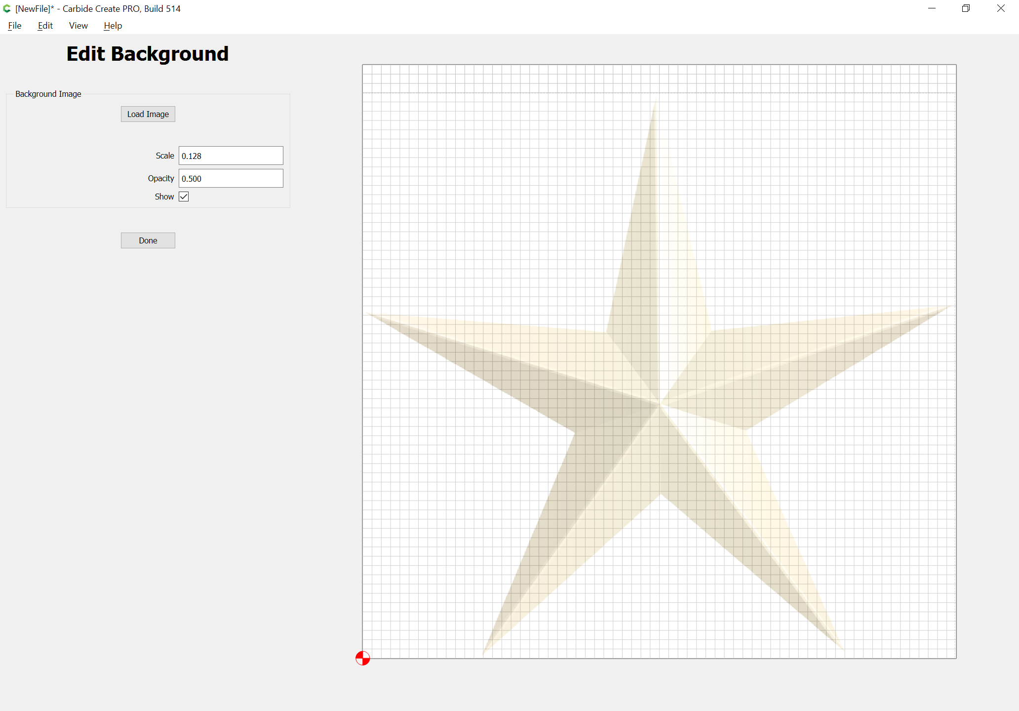
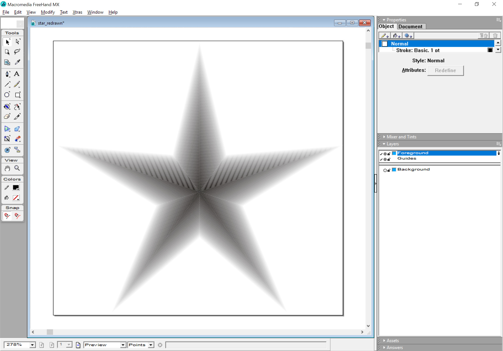
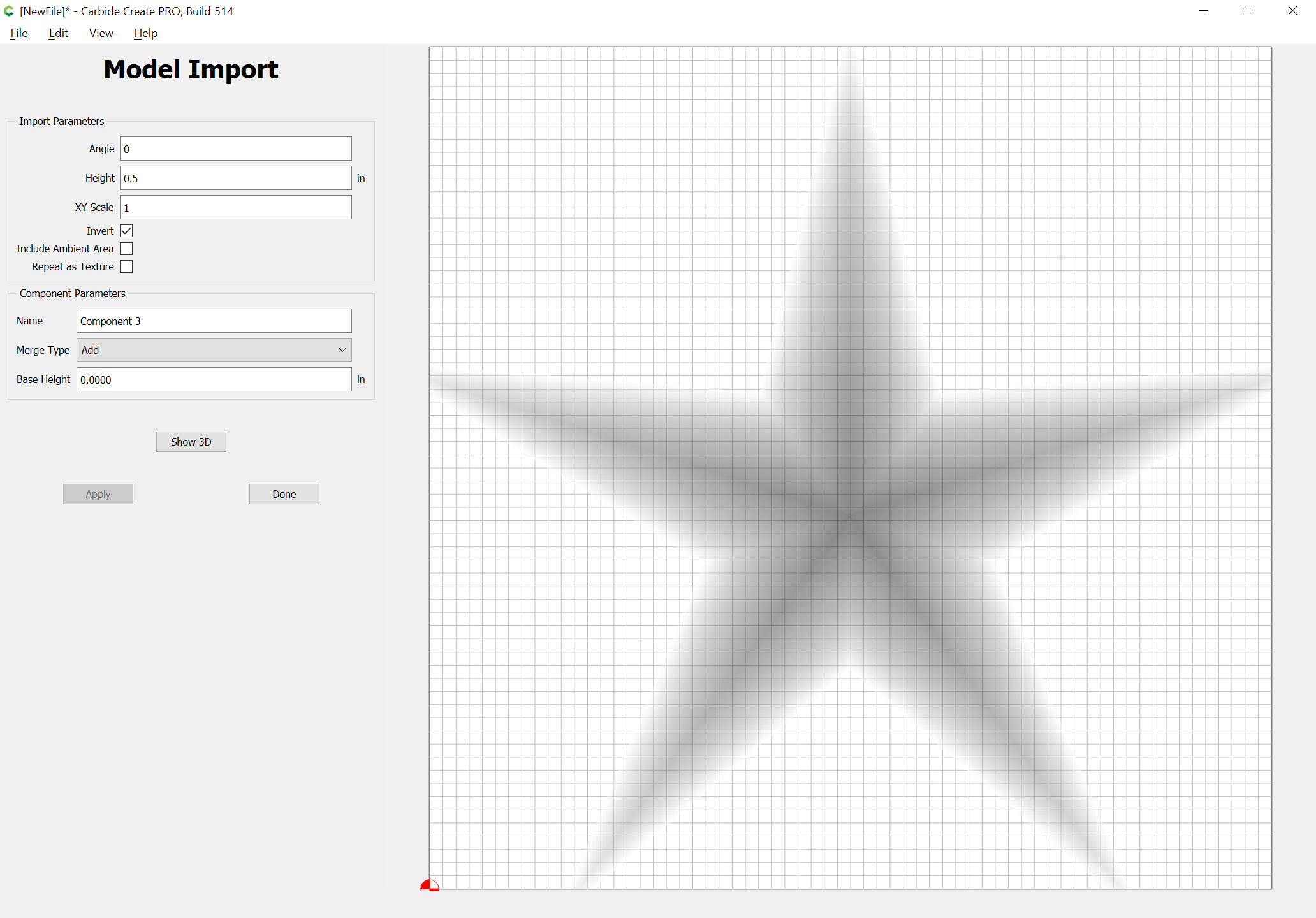
Edward: I want to do something similar, but want my star to be 3D (I think that’s what you’d call it). In other words I don’t want to carve down into the wood to create a star. I want to remove wood so that the star rises out of the wood. I do believe I need to use a .png file, which I have, and in 3D view, looking directly down at the star it looks great, but if you rotate it things don’t look so good. Any advice? Thanks.
William: Haven’t a clue how you do this so fast. YOU ARE GOOD. It’s going to take me considerably more time than you to do this. I’ll get back with you after I am done. Thanks
Andrew: I’m 75 and my eyes are not so good. It wasn’t until I opened your reply again to try working on this star that I noticed you did a very, very kind thing and attached a ready made star for me. I am touched and thankful. I’d like to ask just one more question, if I may. When I opened your attachment I was told that it was made on a newer version of Carbide Create than the one I have. I downloaded my version about two weeks ago, it is a trial version. Is there a newer trial version? Mine is build 474, built of 2020-07-20. Many thanks and blessings.
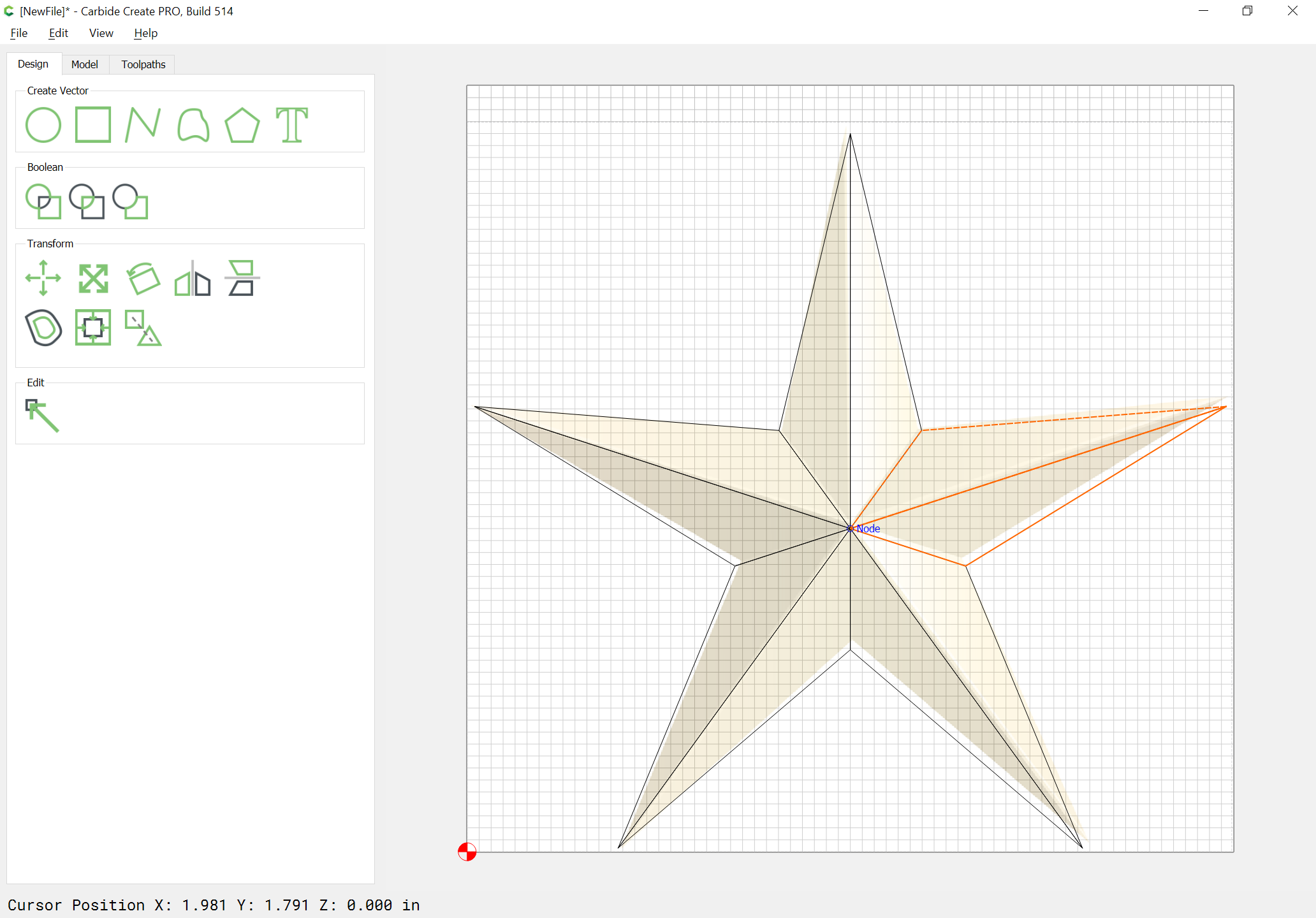
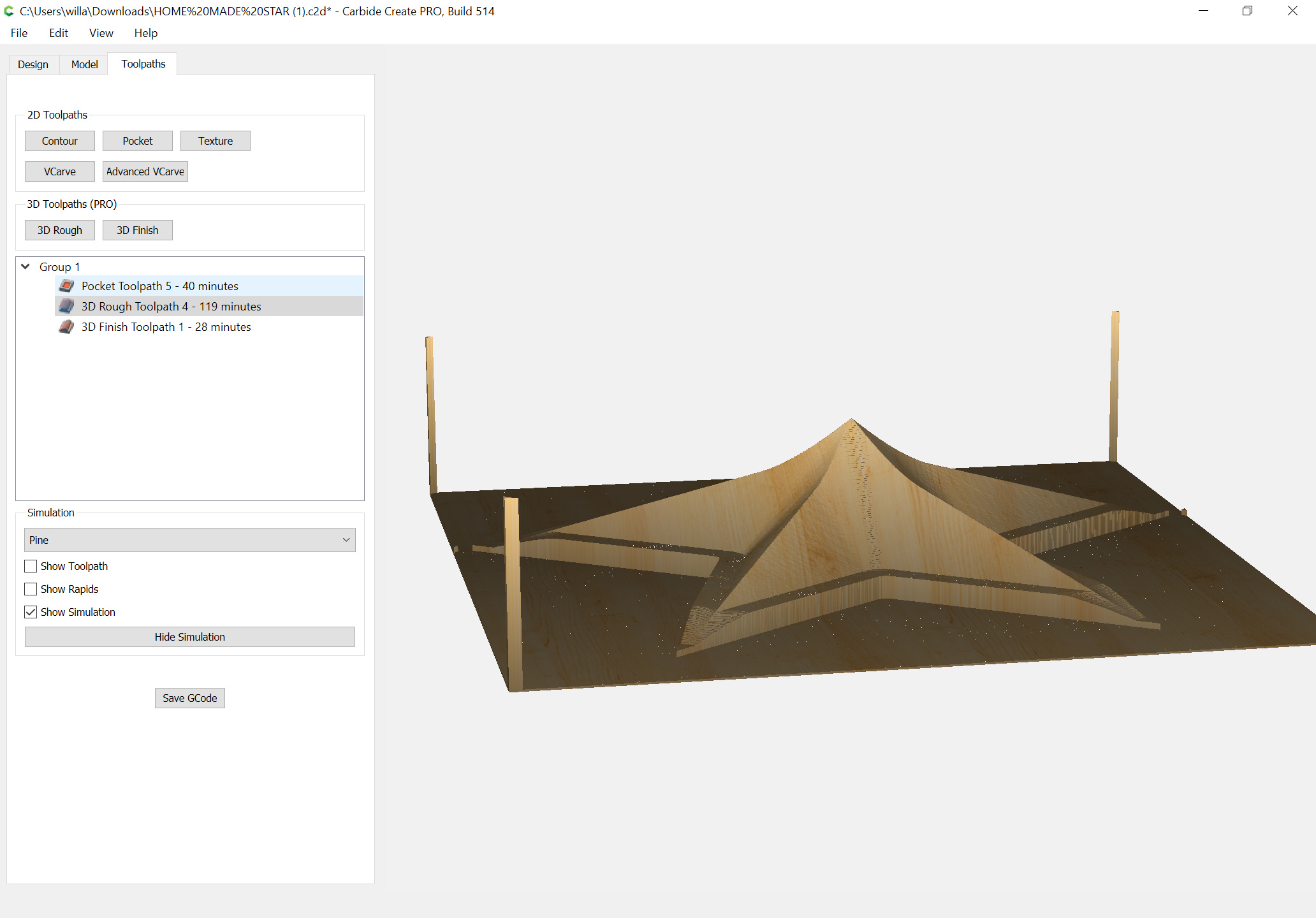
Andrew: I appreciate the star file you sent, but I also wanted to learn how to make it as well. I’ve attached my file and am wondering if you can take a look and comment on it. In the model mode the simulation looks “so so.” The arm are not a nice straight slop and look more like a sagging slope. When I go into the tool path 3D mode the simulation looks a layered 2D.
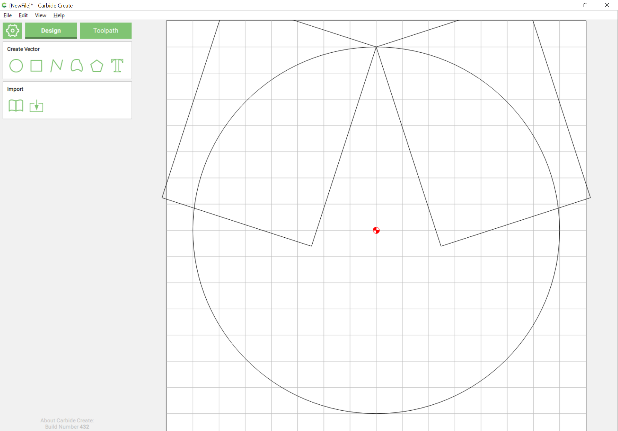
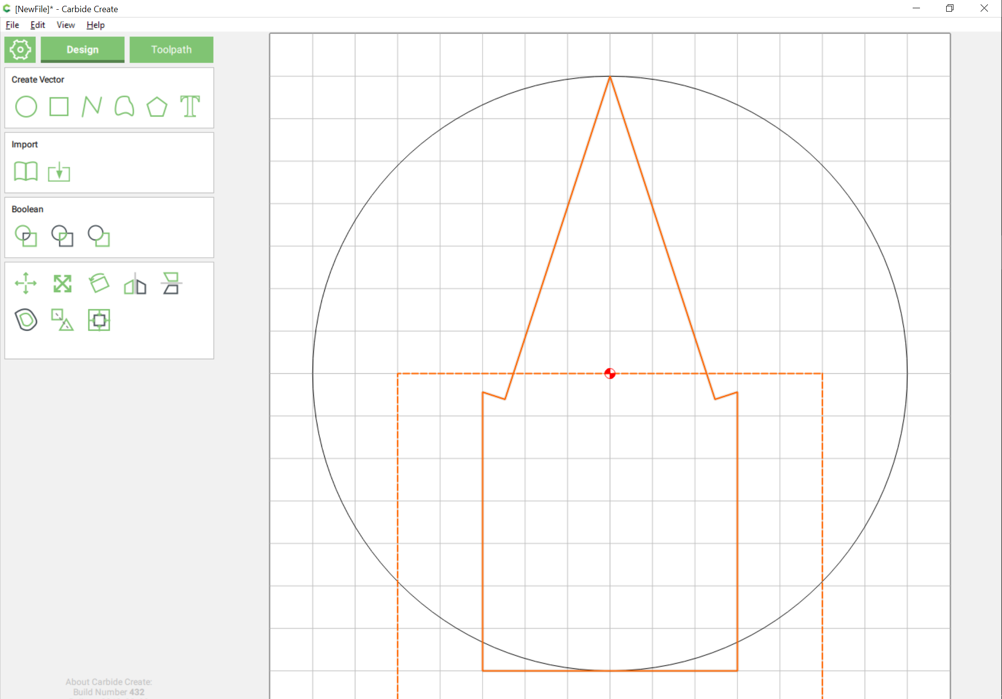
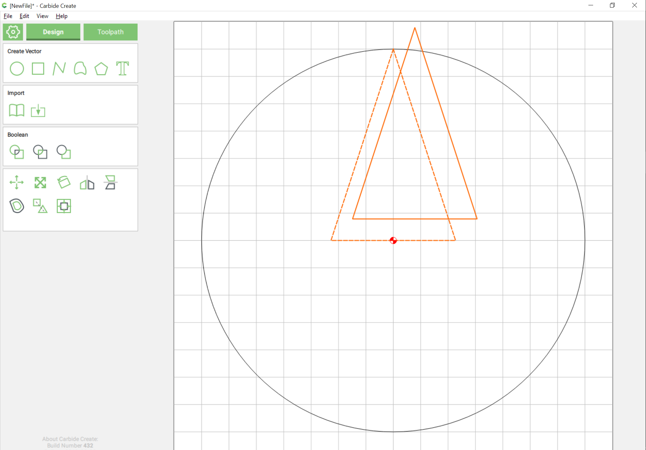
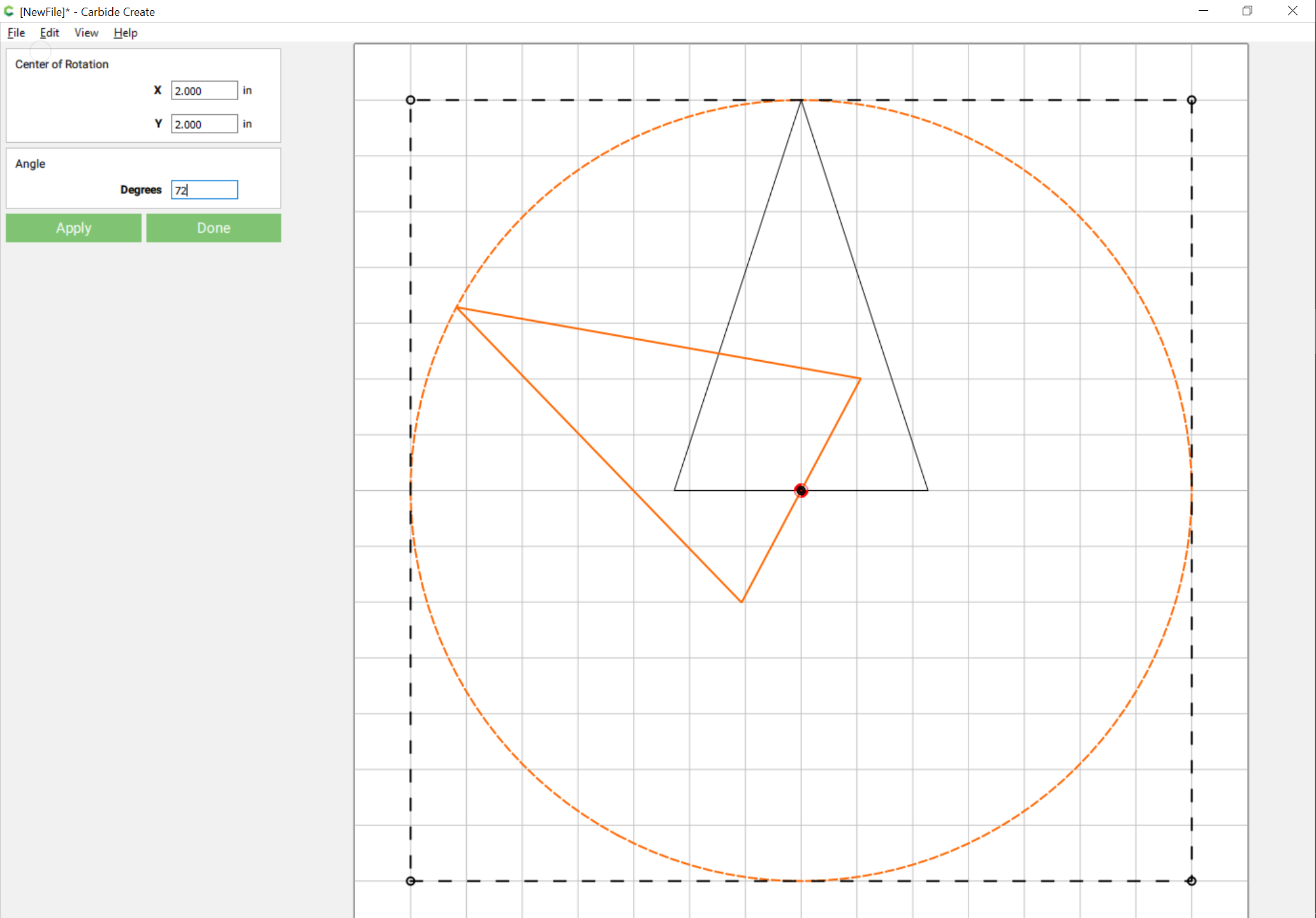
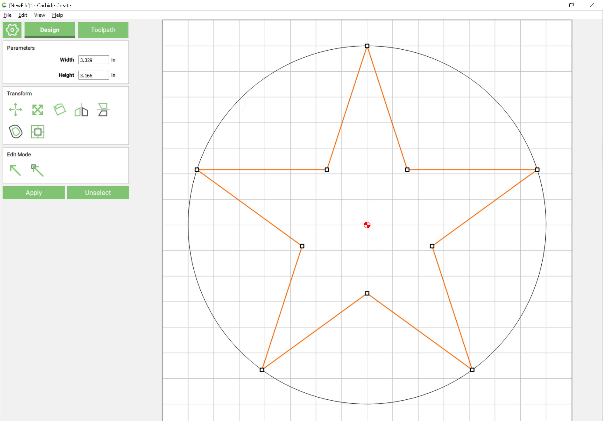
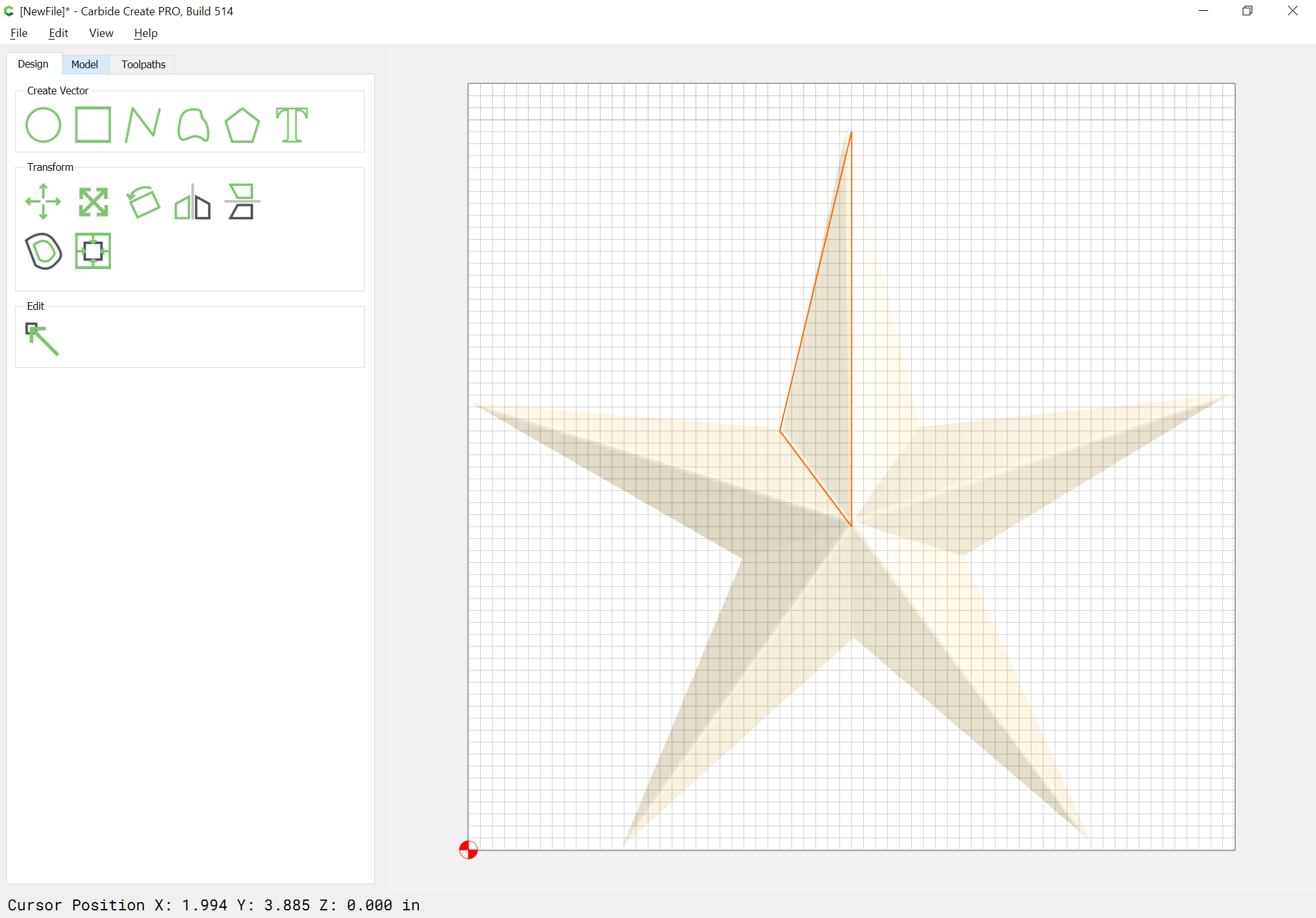
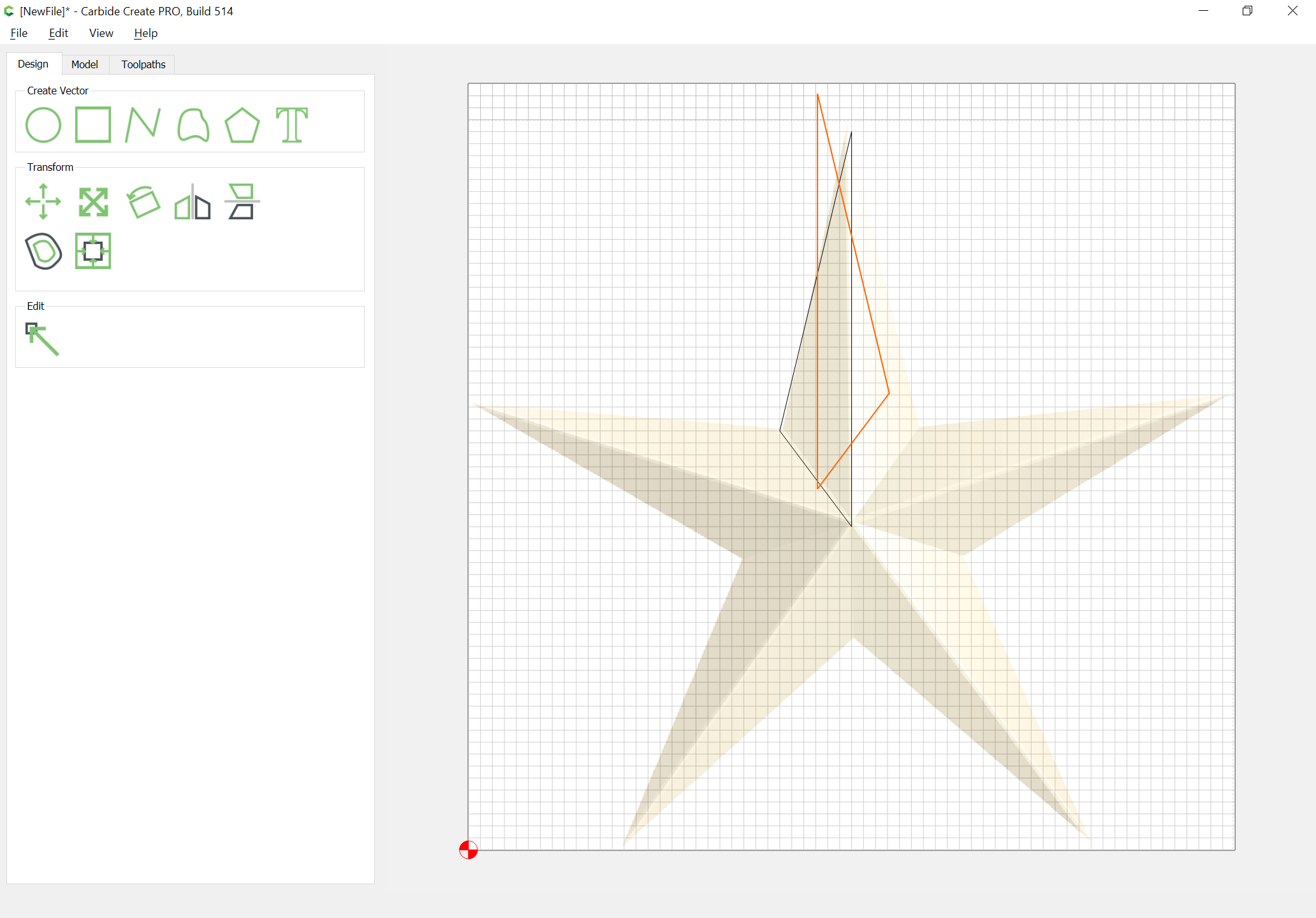
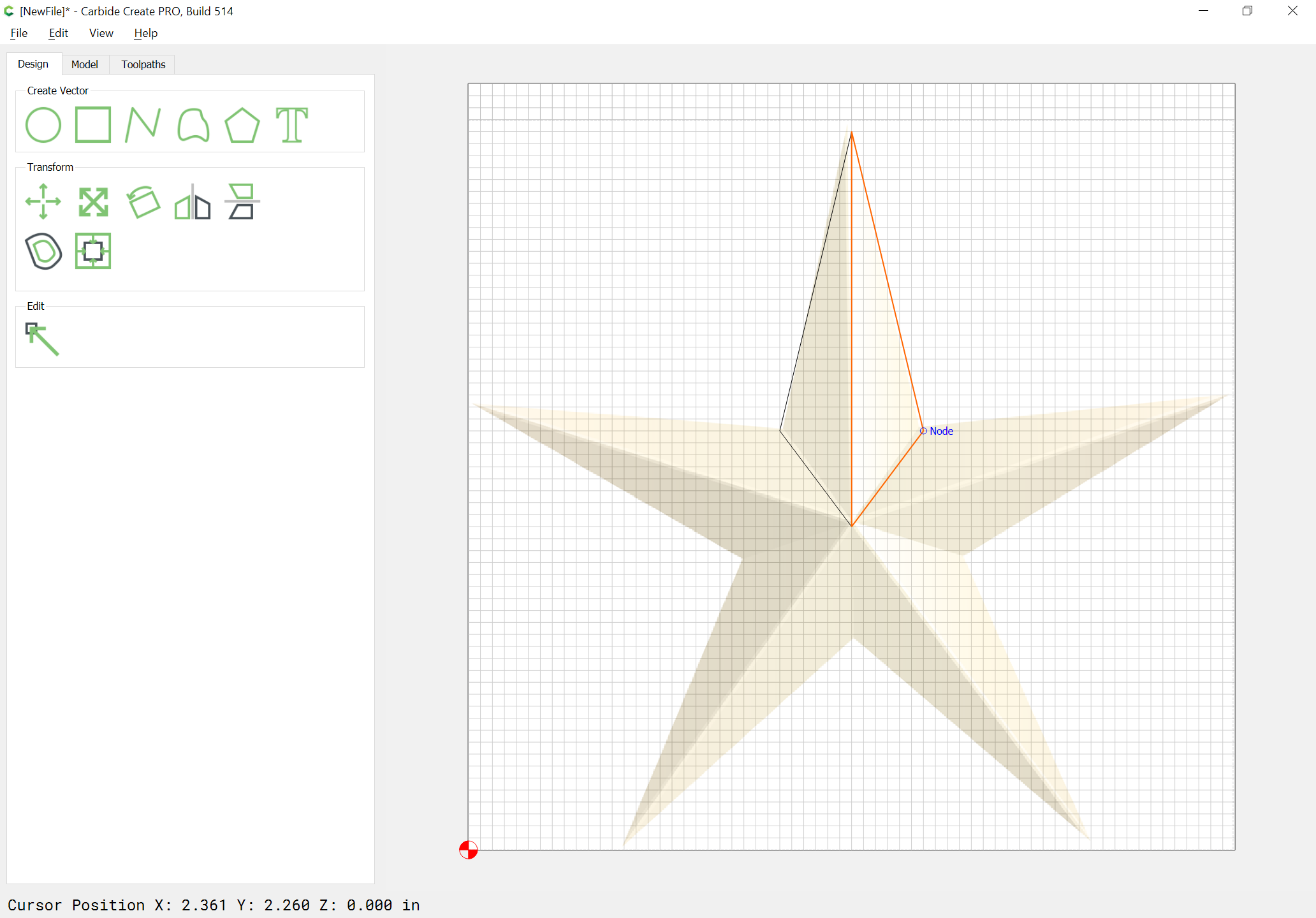
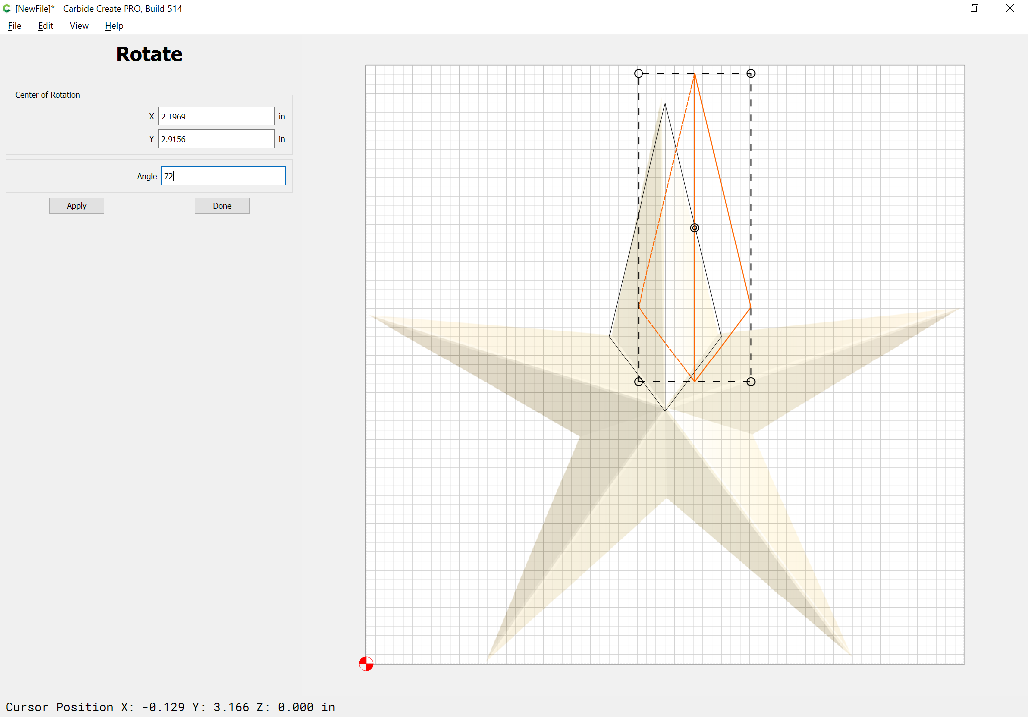
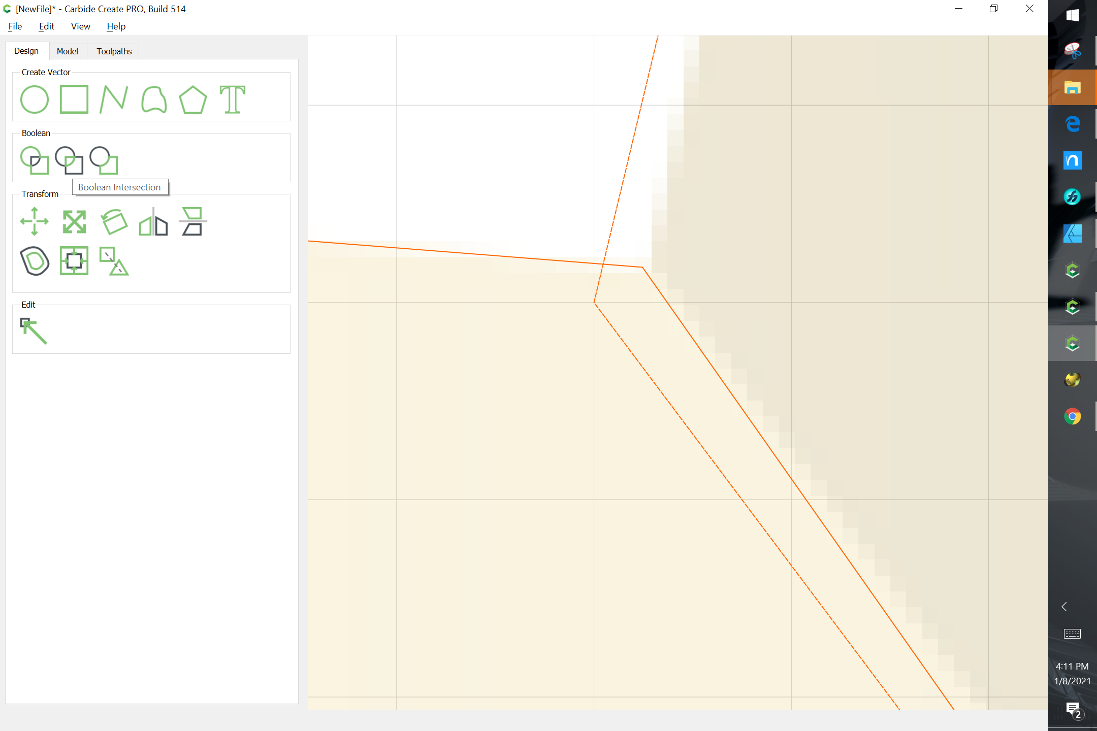
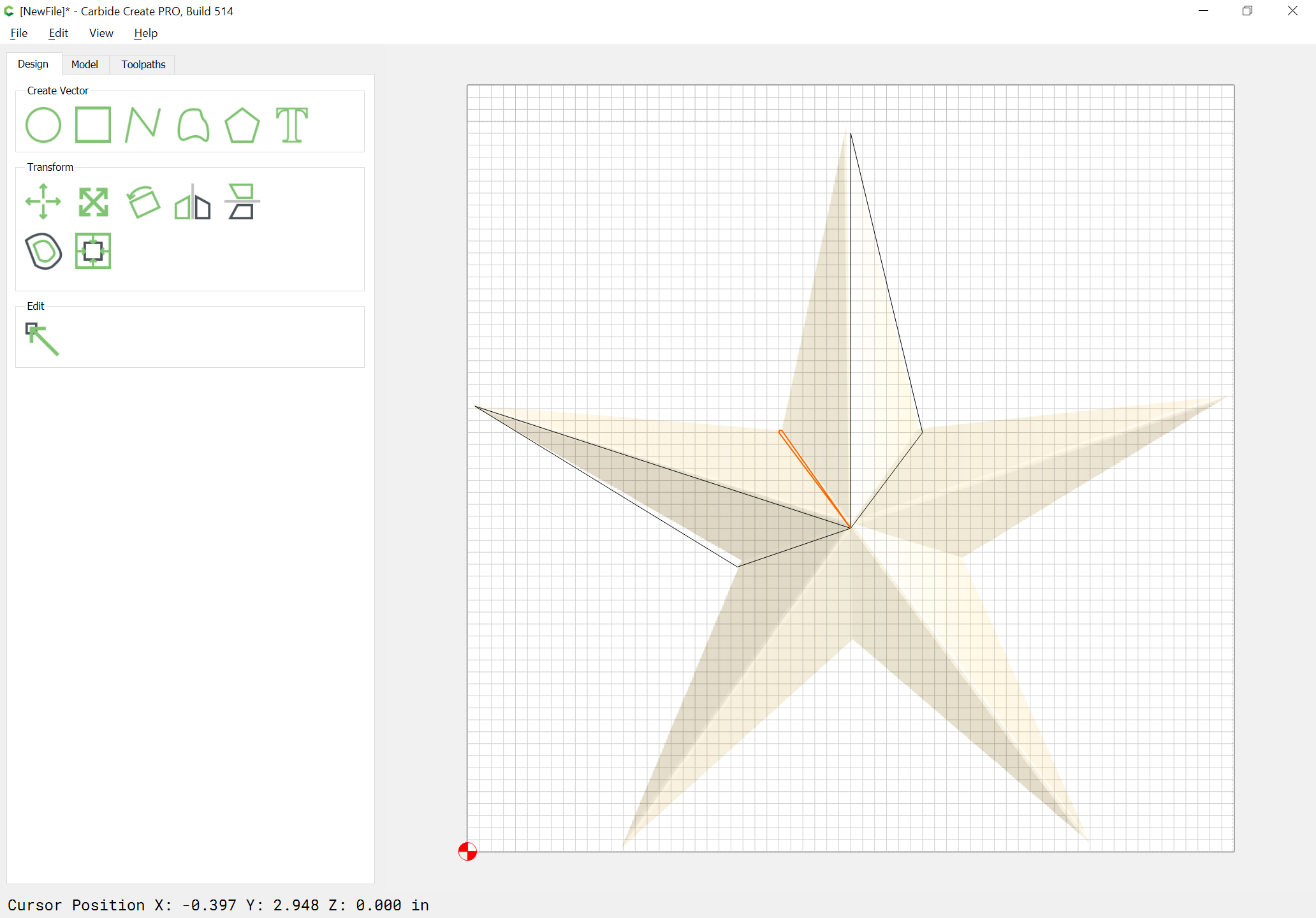
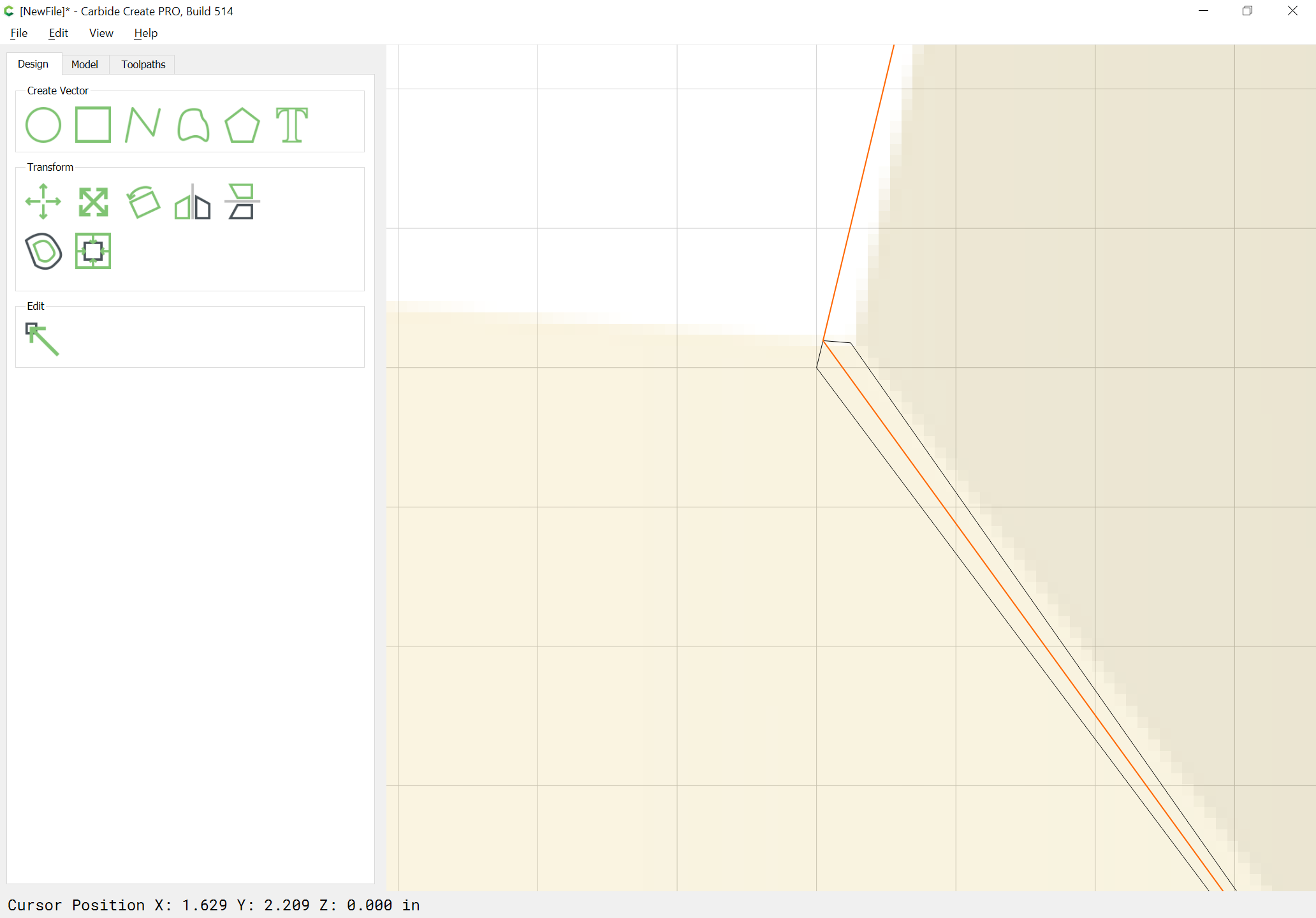
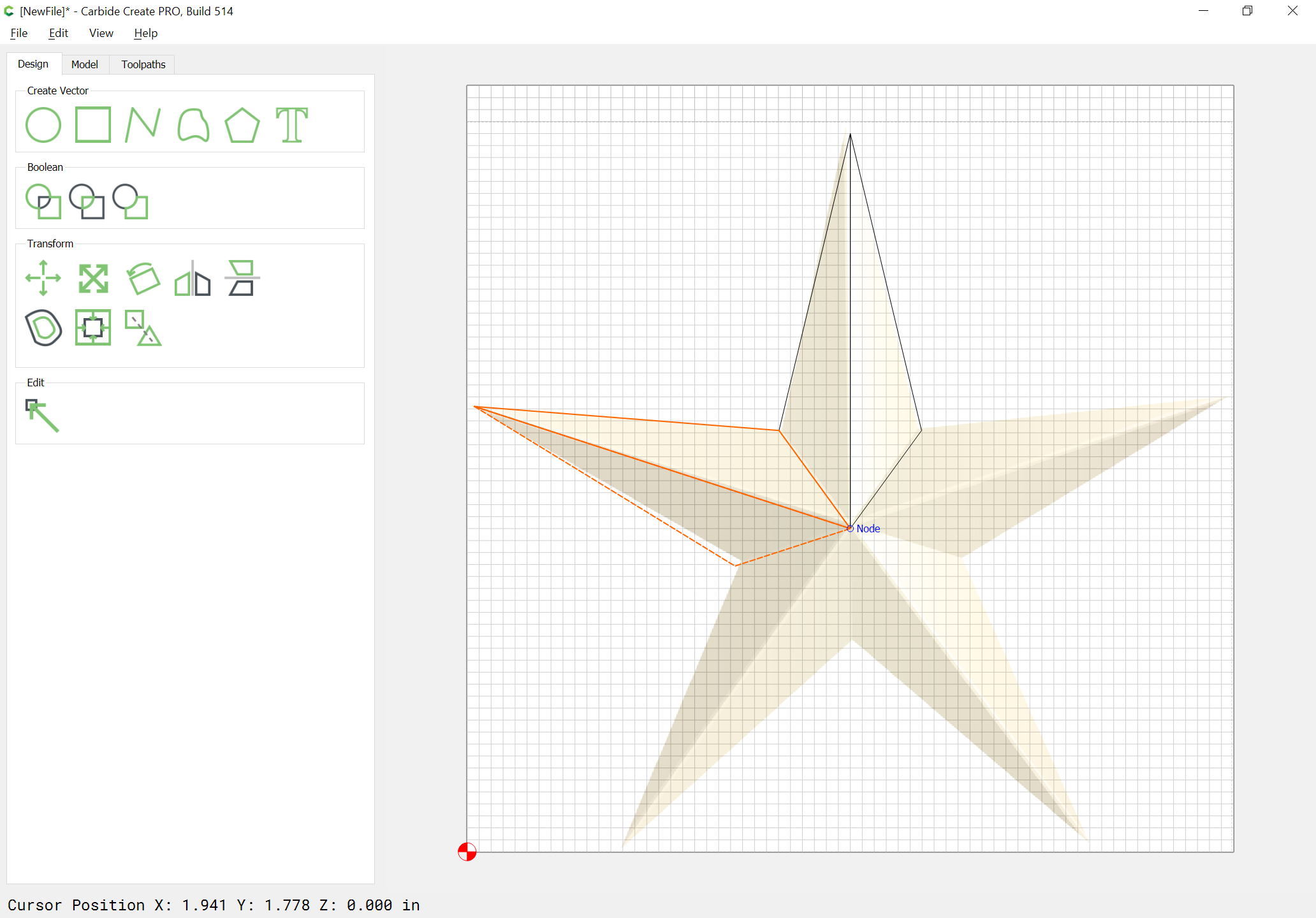
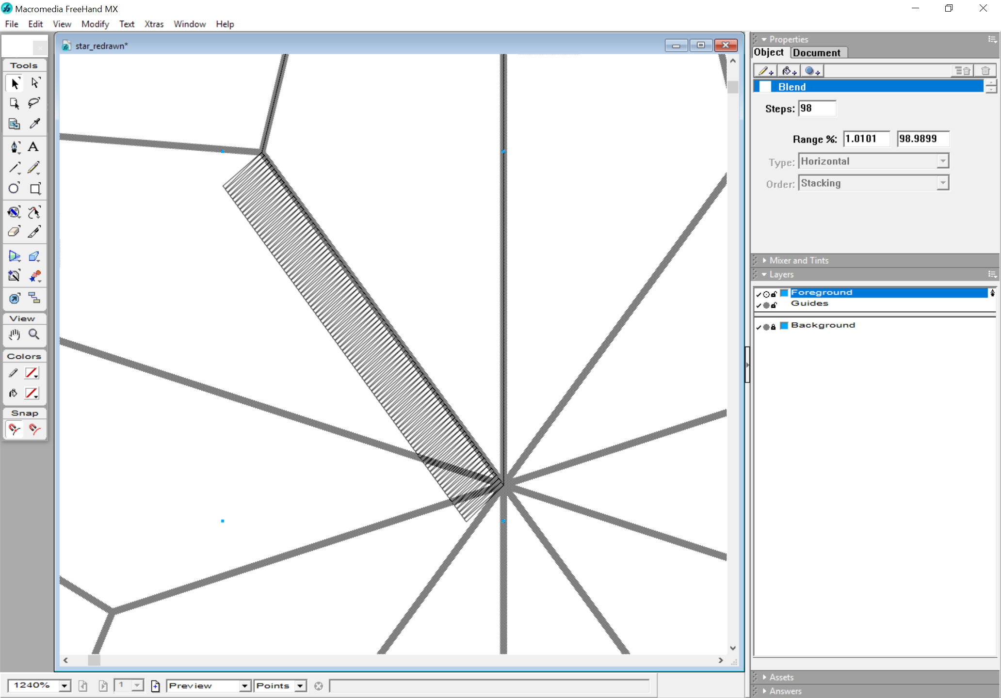
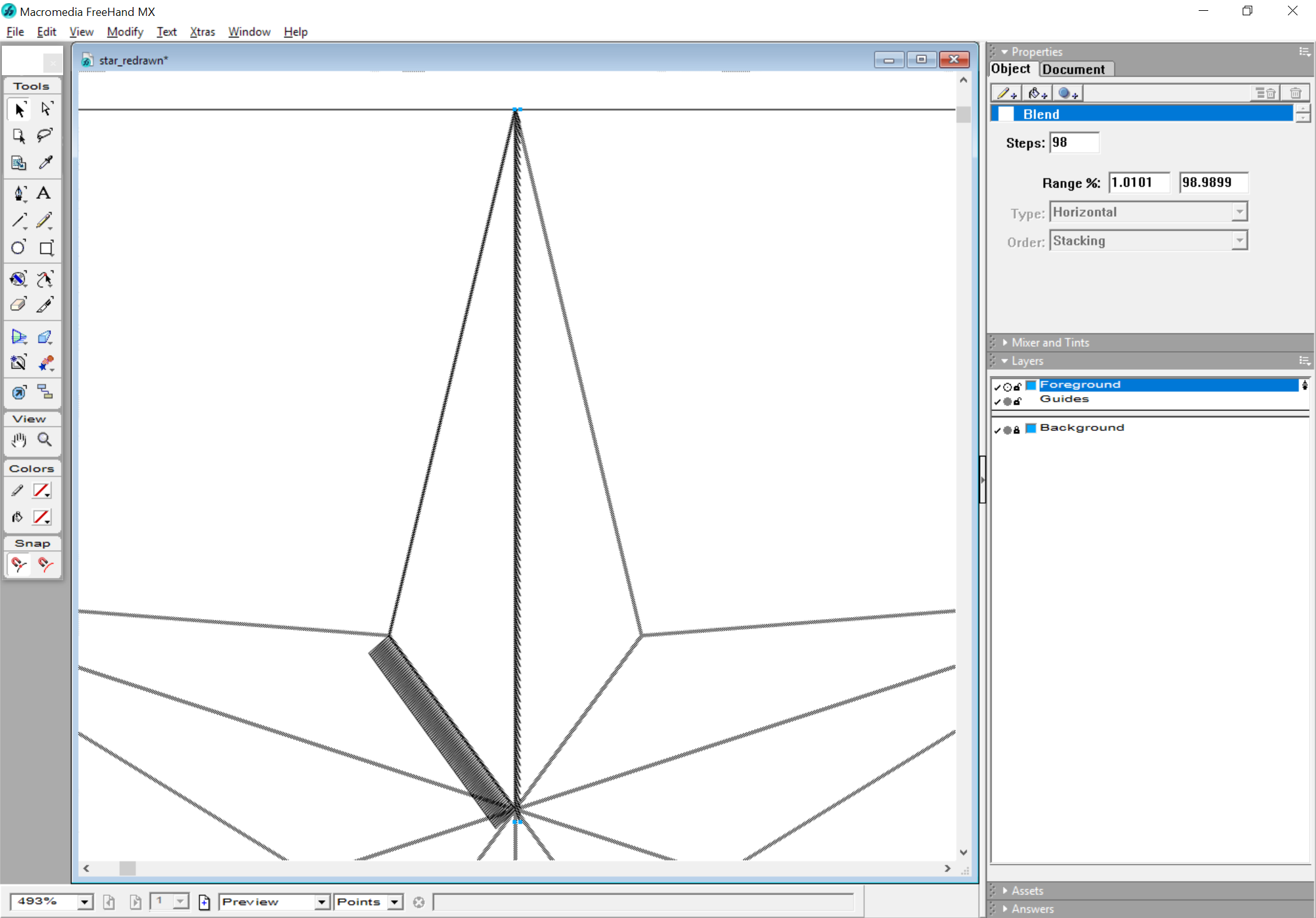
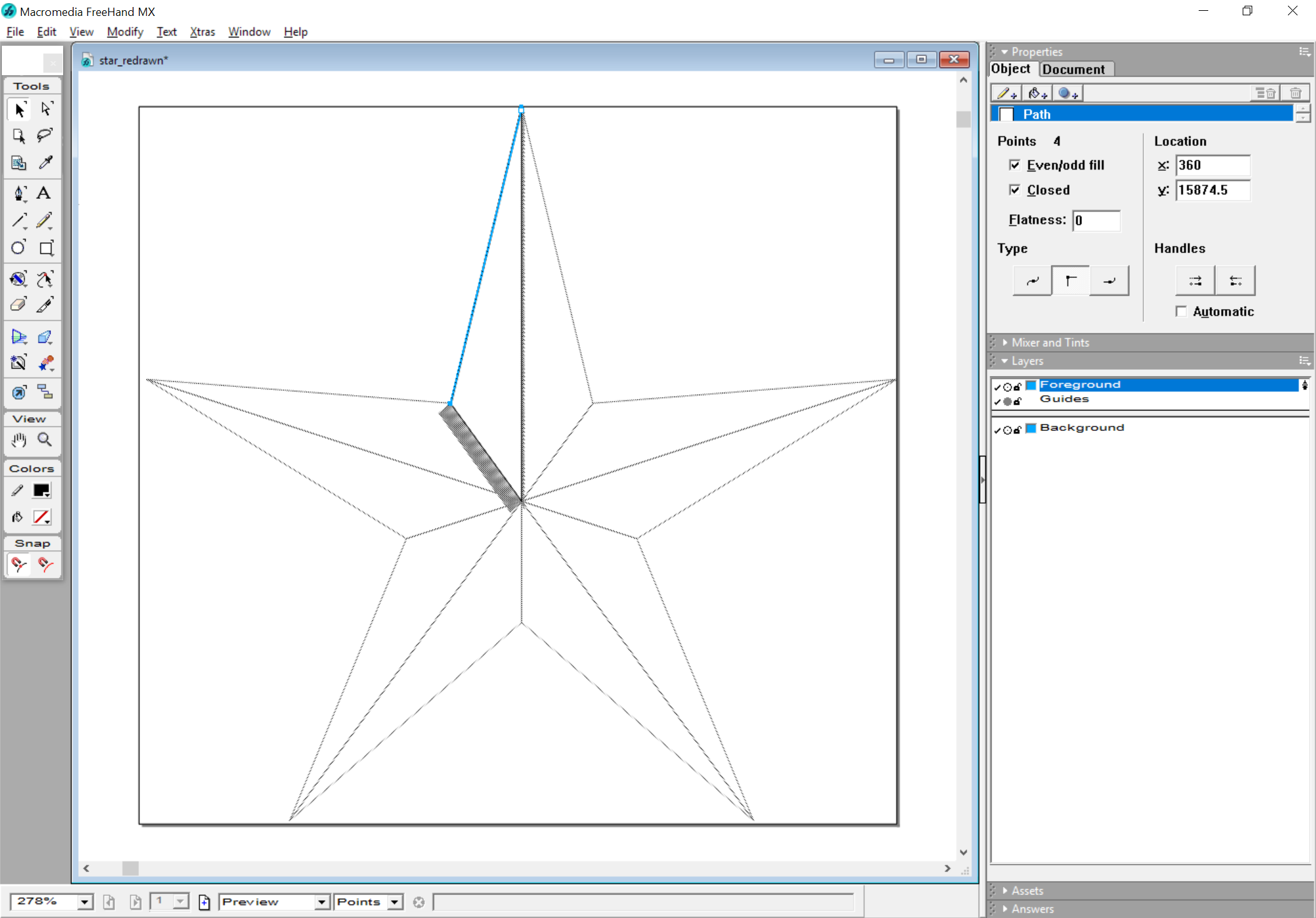
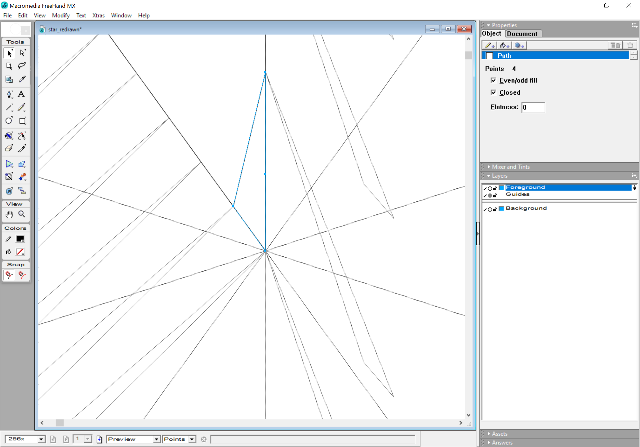
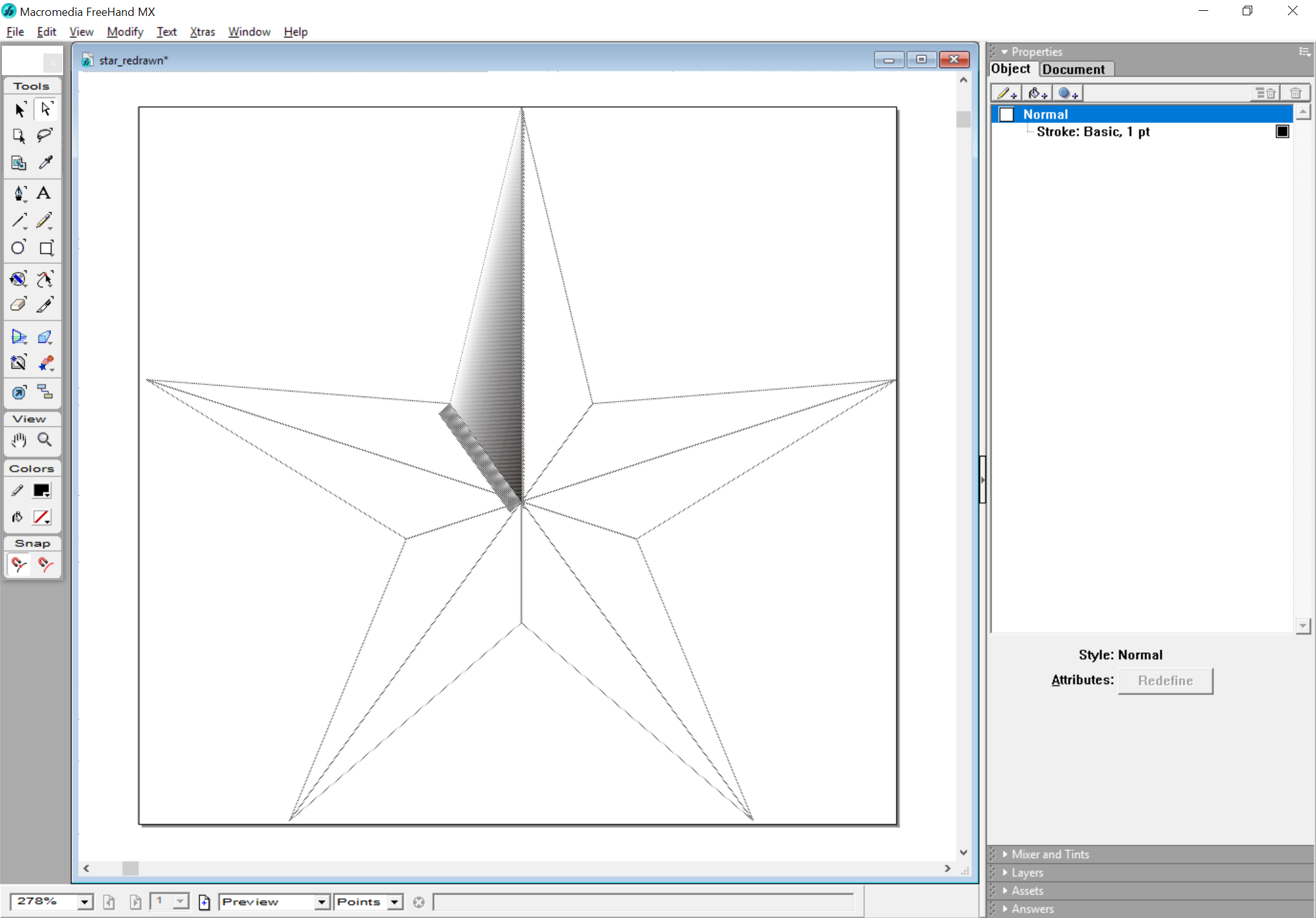
As discussed/shown above, the angles of an even star like that don’t work for the modeling — you need the more acute version to make the angles come out as they ought, but unfortunately Carbide Create doesn’t agree on that, hence my needing to model each step w/ the blend.
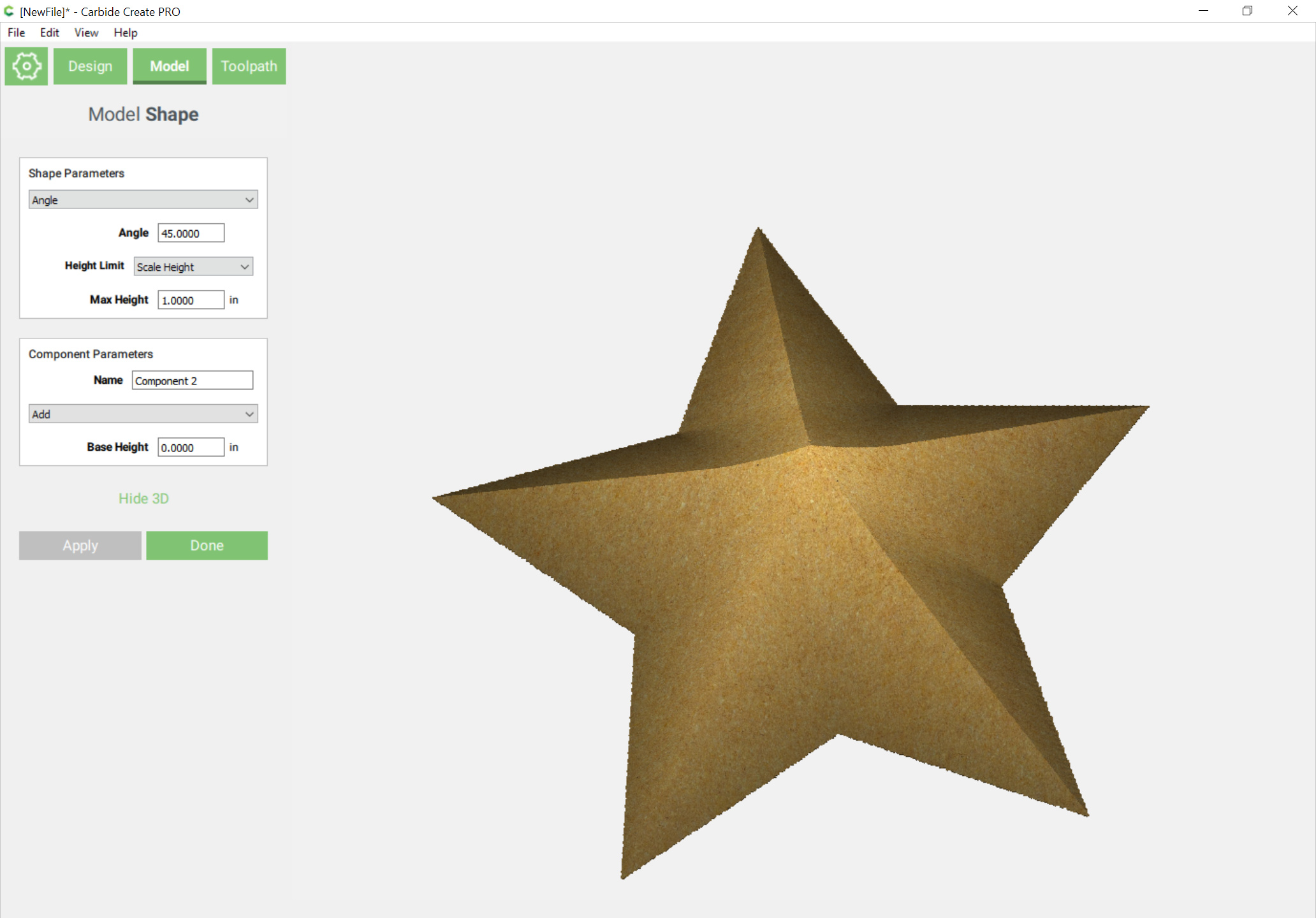
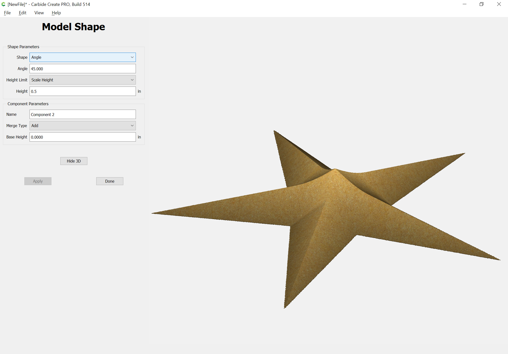
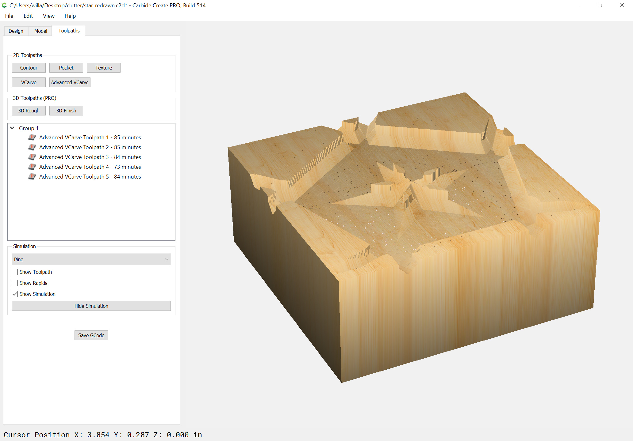
The layered appearance is caused by the component being extruded up higher than the stock thickness:
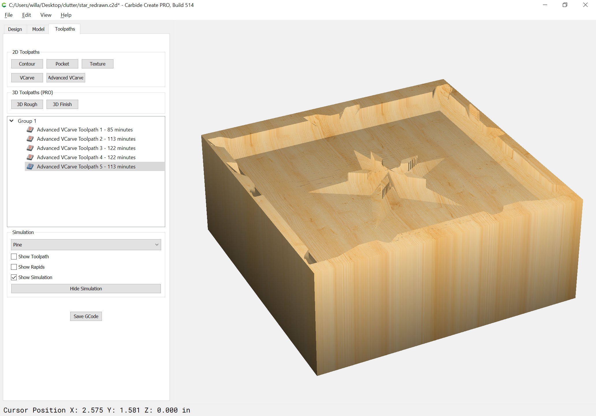
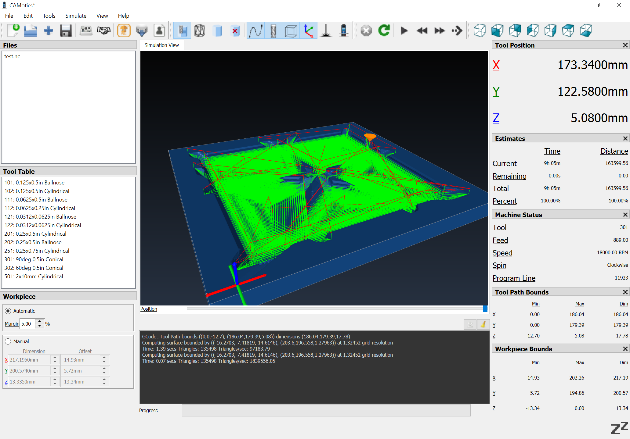
William: I have modified my file to the point that it is acceptable as an experiment that I’d be willing to run, with one exception, the amount of time. I have attached that file and am wondering if you’d take a look at it and tell me if it might be possible to cut down that run time.
And a 3rd party previewer seems to indicate that it is caused by the V endmill being represented as a truncated cone — I believe it would cut correctly.