New user questions

Just learning to use Carbide Create, free version.

When I create a rectangle , I close it up using the nodes and it works fine, turns black.
but when I generate the two long sides with “offset”, then erase the original line, close it up using nodes, it will not turn black. Stays purple.

When drawing a single line, I see the length and angle, but it is not controllable enough, too squirrelly, can’t get exact angles wanted. Is there a way to input the length and angle with keyboard?

Hmm, Not sure what you mean with the rectangle & offset. Can you capture a picture & post it?

To create a line at a specific angle, create it at 0° (horizontal), then rotate it by a specific angle. Then move it into position using the nodes & grids.

Please post the file in question.

I don’t know how to post the file.

I’m drawing a 12 sided polygon with thin rectangles radiating outward. I first drew a line perpendicular (I wish there was a command for that), then offset both ways to make the rectangle. It will not turn black.

I need to be able to input the angle and length–mouse too shaky.

can’t access “setup” after project is started

I’m guessing these are the facts for the free version?

No, the free version doesn’t have any such limitations.

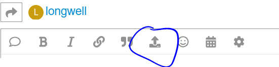
Upload the file using:

image

As noted above, draw the line:

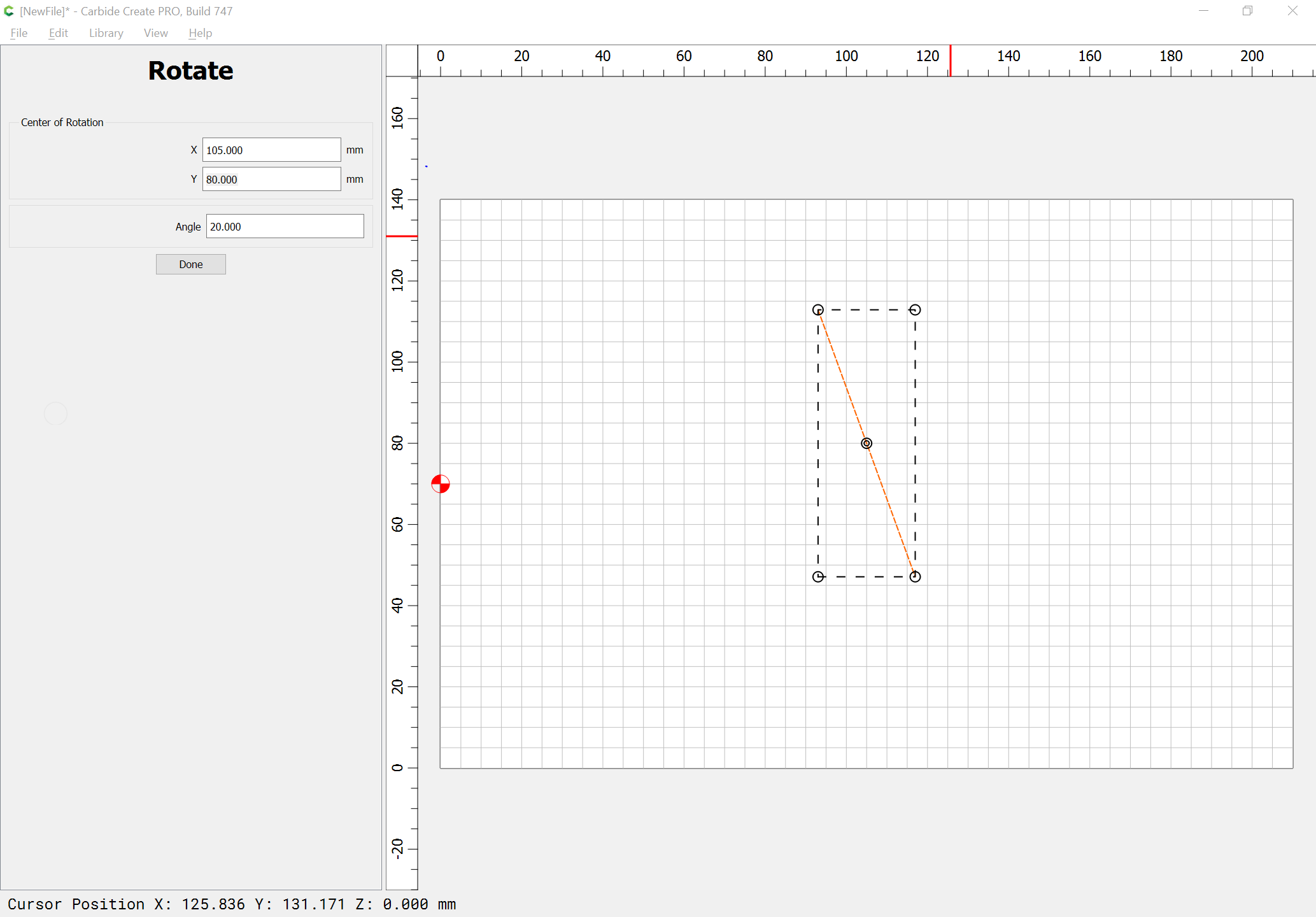
Then use the Rotate command:

It may help to see:

Thanks, nothing to upload yet. I figured out how to rotate a rectangle to any angle. Now I gotta figger how to center it on the dodecahedron facet.

how do I move the grid, so I can zoom in on peripherals?

Ok, if I understand correctly the thin rectangles radiate out from the middle of each edge?

draw your polygon

image

Now rotate it (360 / 12 / 2) 15° to get the top, bottom & sides flat.
Note, DON’T hit enter after typing the angle, just hit Done. (else you’ll do it twice)

image

Now create a horizontal rectangle the size you want

image

Select the midpoint on the left end, and move it to the midpoint on the right side of the polygon

image

Leave it selected, and pick the Circular Array tool
image

Select the center as the same point you used as center of the polygon, and set number of items to 12

Not sure what you want to do here, you could Boolean Weld them into one shape

image

offset the polygon & then weld the outside shape

image

And Setup is only visible when you have no objects selected. (Context sensitive menu)

1 Like

great thanks. the polygon is temporary. your “array tool” is the ticket.

the rectangles will be cut out of 3/4 ply to hold xylophone bars.

so the rectangular holes will be of diminishing lengths.

Need to figger how to draw the spiral that will be the outside edge of the plywood.

Next time lead with this!! :slight_smile: Along with some dimensions :wink:

If you adjust the inside edge of the slots, the outside will still be round :wink:

1 Like

thanks, man, I hope they’re paying you well.

when I zoom in or out, the grid moves sideways? how to put the grid where I want it?

the overall shape will be a spiral, since xylophone bars are of different lengths. I suspect the curve tool will do it?

The Curve tool will allow you to describe/draw a spiral, but it will not allow placing geometry along the spiral.

Please sketch out what you are trying to achieve, label it w/ dimensions, then post a .c2d file showing how far you’ve gotten and we will do our best to walk through this w/ you.

Thanks, It will take me a few days to get it all dimensioned. I still have to find out if your program is compatible with the CNC machine at school. UCF, Orlando Fla

I’m also looking for software to design flutes on the lathe. Holes will be located by tube length plus a radial angle, 0 thru 360. Possible oval hole and maybe undercut?

how can I convert a Jpeg to c2d?

I can’t find “Array”

You would need to model the flutes in 3D, or use a machine w/ a 4th axis and appropriate software.

To convert a JPEG see:

For Array, select something:

Thanks but I’m not finding the toolbar with the “send” arrow.

I figured out “array” but now I see I cannot change the dimensions of individual parts, it’s fused together?

No biggie, I now know how to create each rectangle and put it in place.

Now I’m asking how to move the grid so I can zoom in wherever I want.

Can I email you a jpeg?

Yes, many of the functions in CC are not associative or parametric. Once the object is created, it’s just there.

You can’t move the grid. It’s always positioned from the lower left corner of the workpiece. You can only change the spacing. You can however, move the geometry relative to the grid, work on it then move it back to where it was. You have to get creative sometimes, and it helps a lot if you stayed awake during math/geometry class in school. :laughing:

thanks. the only way I see to zoom, it with the roller on my mouse. When I zoom in, the grid slides to the left, going out of sight. I’ll try to just move the work back into view.

centering the long rectangles on the inner polygon, I see no way to snap node to a center point, will have to align each one by eye. ??

Certain types of objects will have a center point.

You can pan around w/ a right-click-drag

Please see:

https://carbide3d.com/carbidecreate/shortcuts

and