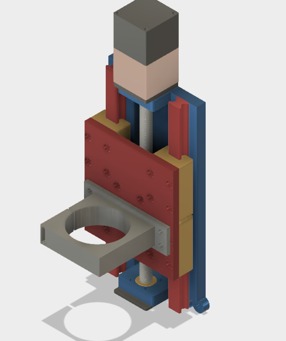
Since posting my original Z upgrade I wanted to improve it (@TommyG showed me up ) From there I decided to learn how to use fusion a bit better. To cut a long story short, I have made a revised design of the linear Z axis for the shapeoko and remove the confusion behind all the designs floating in the original topic.
Now there was nothing wrong with the first design but this is heavy duty… It’s not as pretty as Tommy’s design but functionally it should be spot on.
It uses HGH20/HGW20 sliders - more ridged and smoother operation. longer lasting and less flex.
There are less parts to make - down to 5.
It’s simpler
I removed the confusing upgrade opps later for X axis
You should get 140cm of travel
Tram though front mounted screws and eccentric nuts
Now there are a few things worth noting;
It’s slightly bigger and thicker than my original design - this will generally improve it’s smoothness over the X
The plans will require you to add holes for your HGG20 rails - I don’t have a set to hand to work from - I can walk you though this
There is some two sided milling
You will need to tap some threads
Because I haven’t physically made the design yet, you might find some of the holes slightly too small after milling - I’ve assumed M5, but some might need to be made into M6.
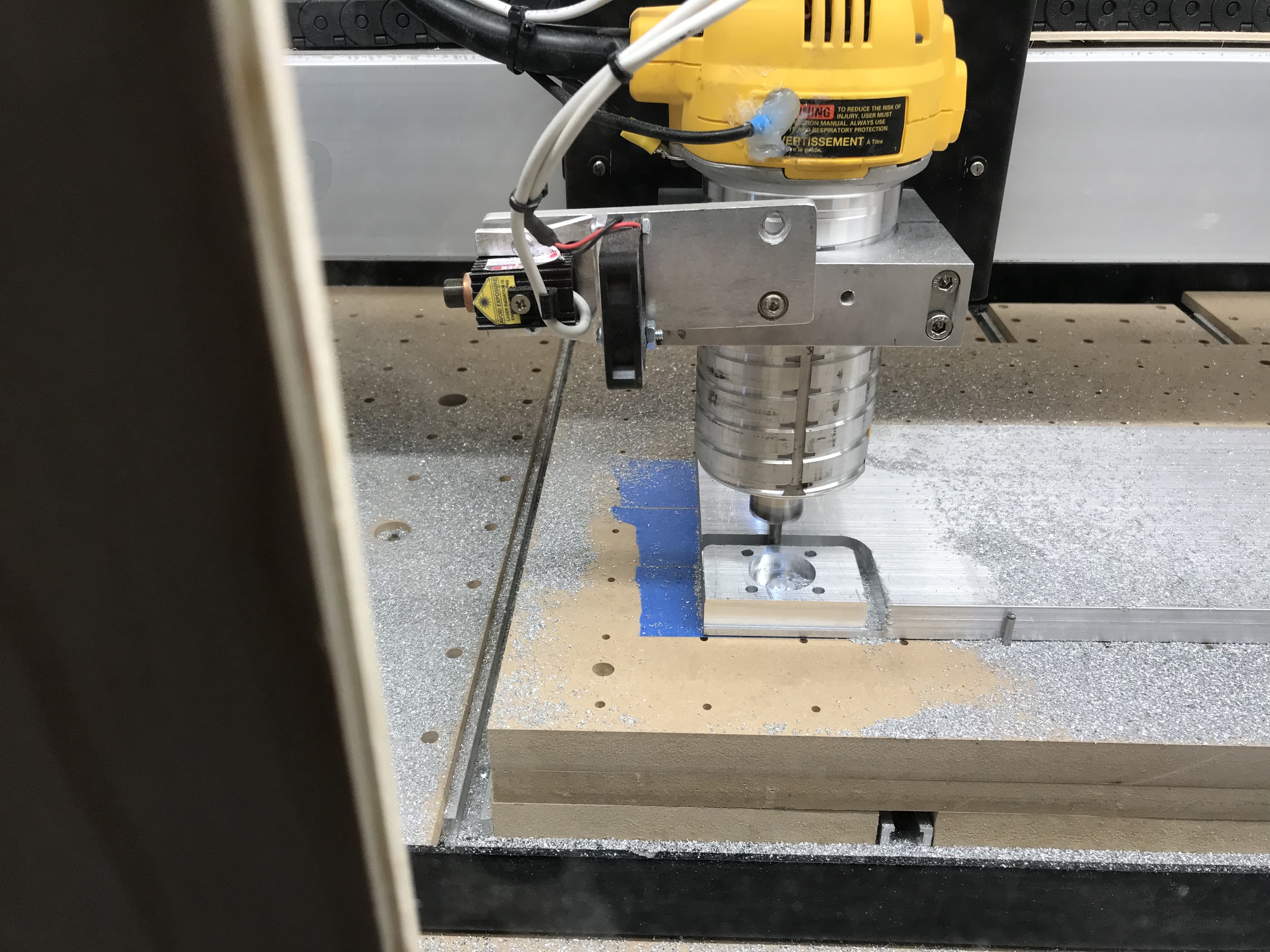
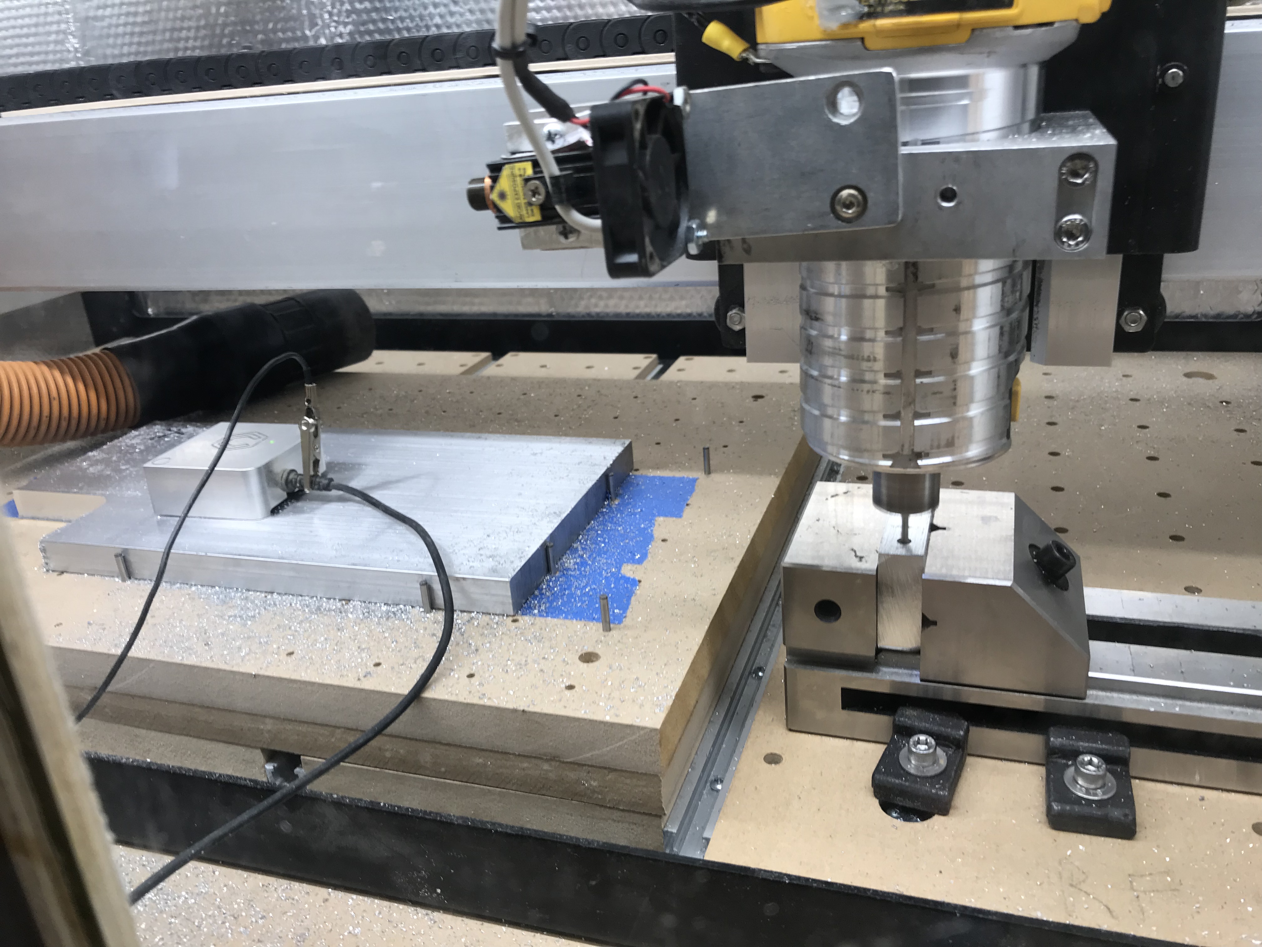
I haven’t added any tool paths - I have a 2.2kw spindle and the speeds I put in were not suitable for many.
Thanks Luke, very interested, keep drinking the coffee…maybe a “Lukeoko”…or a “Beavermatic”…
I always buy the expresso grind for my drip coffee maker, it comes out much stronger, but I’d guess you have a handle on that…how about a “SconeCNC” to celebrate your “Brit” initiative, okay enough “musing”, good job.
“Beaveroid CNC” Jude
checked out your youtube channel Luke, subscribed too.
When the tales of this time come to be written down* in the annals of history, the day I innocently suggested to @Luke that he take another look at the ‘Joint’ function in Fusion 360, that’ll be the day the monster was created.
* Or scribed into holo-crystals **
** or finger-painted onto the walls of caves
I don’t believe that those cave paintings were authentic art work for generations to come… just like we hang our kid’s paintings on the refrigerator the cave mom’s let their kids paint on the cave walls, hence the “bigfoot” cave drawings were really the little one’s best effort at drawing mom and dad. What else did they have to keep them occupied? Some might have been really good but it was still just the kid’s artwork. Don’t get me started on “dinosaurs” musings…but save your sketches Luke, next few generations might see something…Leonardo did…
When I follow your lead, I probably will keep my makita router (no new spindle budget), this would hang out in front of the assembly farther than your 2.2 spindle (I think)? Trying to consider the leverage force on the “v” wheels", but I like your thinking about a second plate in back for 4 more “v” wheels ( 4 front and 4 back sides). It seems your assembly is solid and steady vertically (tram wise) even with the extra weight of the big spindle ? (seems pcsavant had play tram wise in his kit version)…
So a lighter router should poise no problems of stability tram wise. On your utube you mention adjusting the tram with shims and screws… at some point in the future, please note a discussion of this ability. Thanks Luke
Just remember @TommyG - you pushed me over the edge
@Jude, are you saying additional 2 wheels on the rear? If so they could likely be accommodated. Bear in mind my spindle weighs twice a dewalt I’m nut sure it’s needed, but it would make things smoother I guess.
I have been giving tram some thought, the easiest way to add this is to mount it from the front.
Griff
(Well crap, my hypometric precursor device is blown…)
9
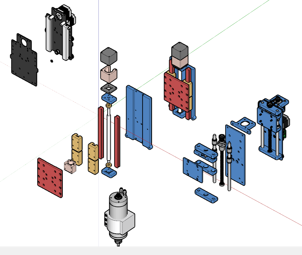
Food for thought… I combined the original S3 Z axis, Luke’s design and Tommy’s design, exploded them for visual reference. It is in sketchup but they are as downloaded from your fusion and all appears intact. So here is a visual reference of the 2 Z Axis Screw Drive Assemblies:
Griff
(Well crap, my hypometric precursor device is blown…)
13
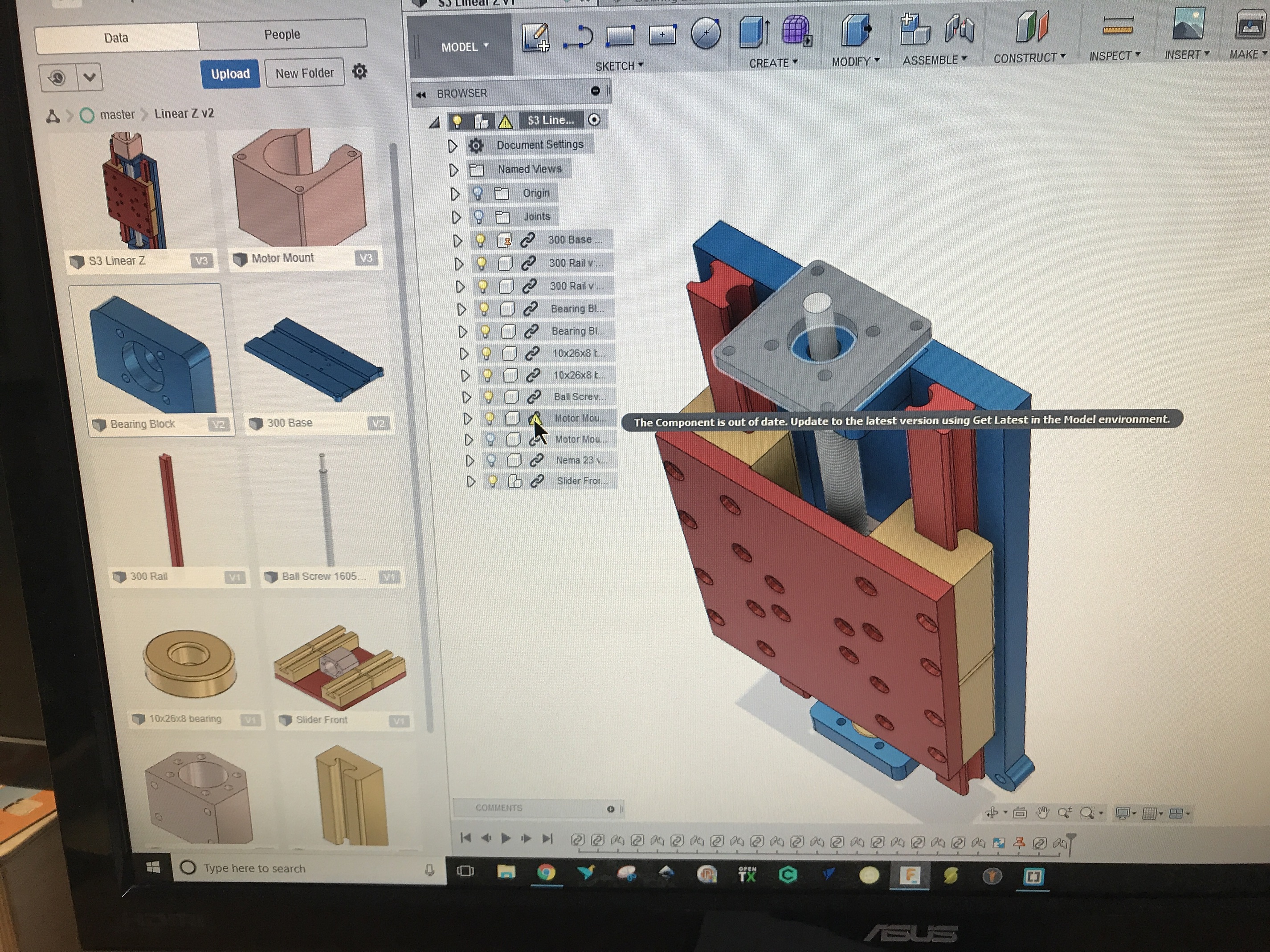
I see the second part of the motor mount in the assembled model but not as a separate part/model. In fact, in the browser it shows as an out of date component.
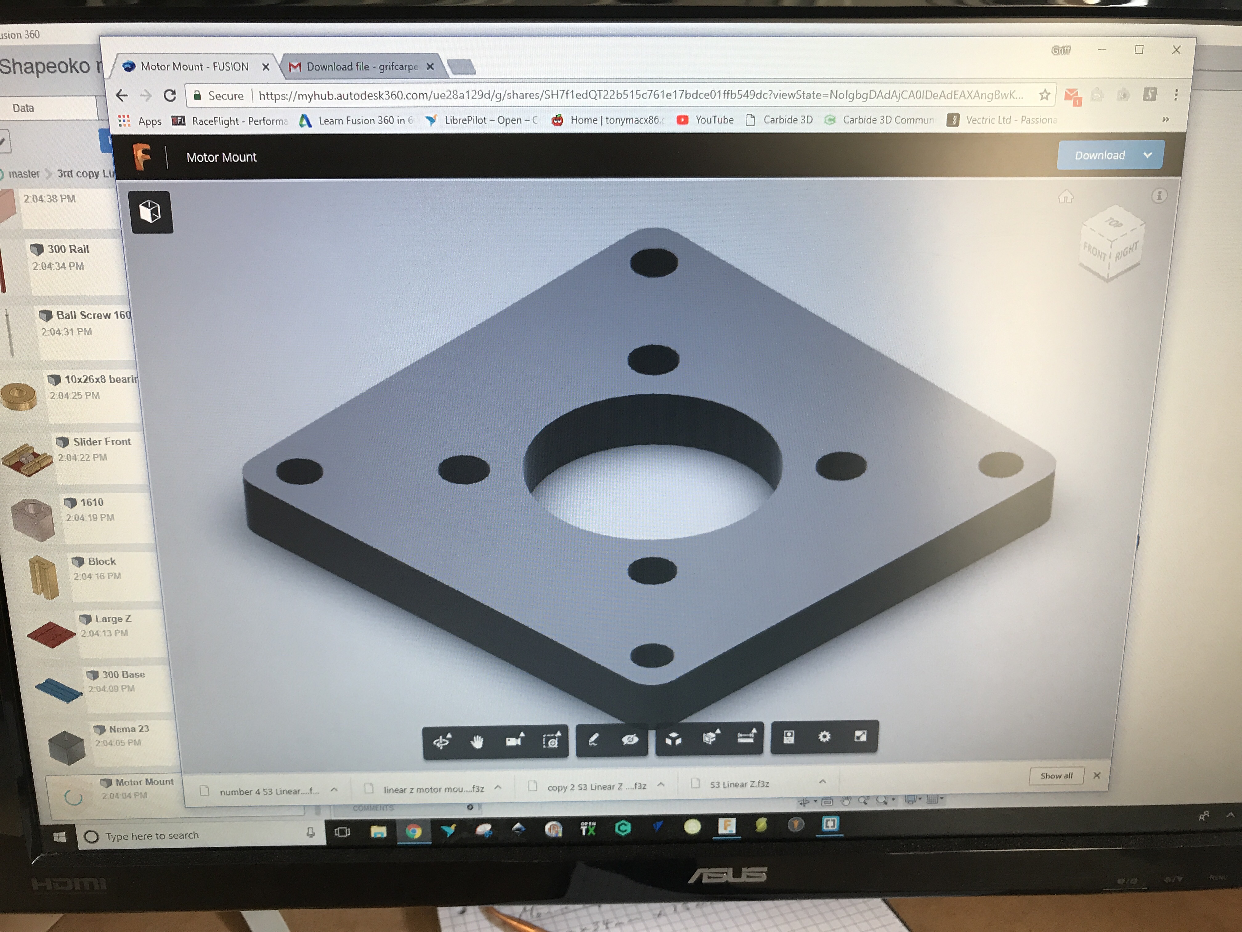
Also, the larger piece of the motor mount is 50 mm thick. I’m not sure I can mill something that thick with accuracy. Not to mention the thickest stock I have on hand is ~26mm. I’d guess making two pieces at 25mm each would be ok?
You only need to make the smaller bit - the 50mm bit is one you buy in - link is above in the first post.
You could also use 50mm spacers.
Griff
(Well crap, my hypometric precursor device is blown…)
16
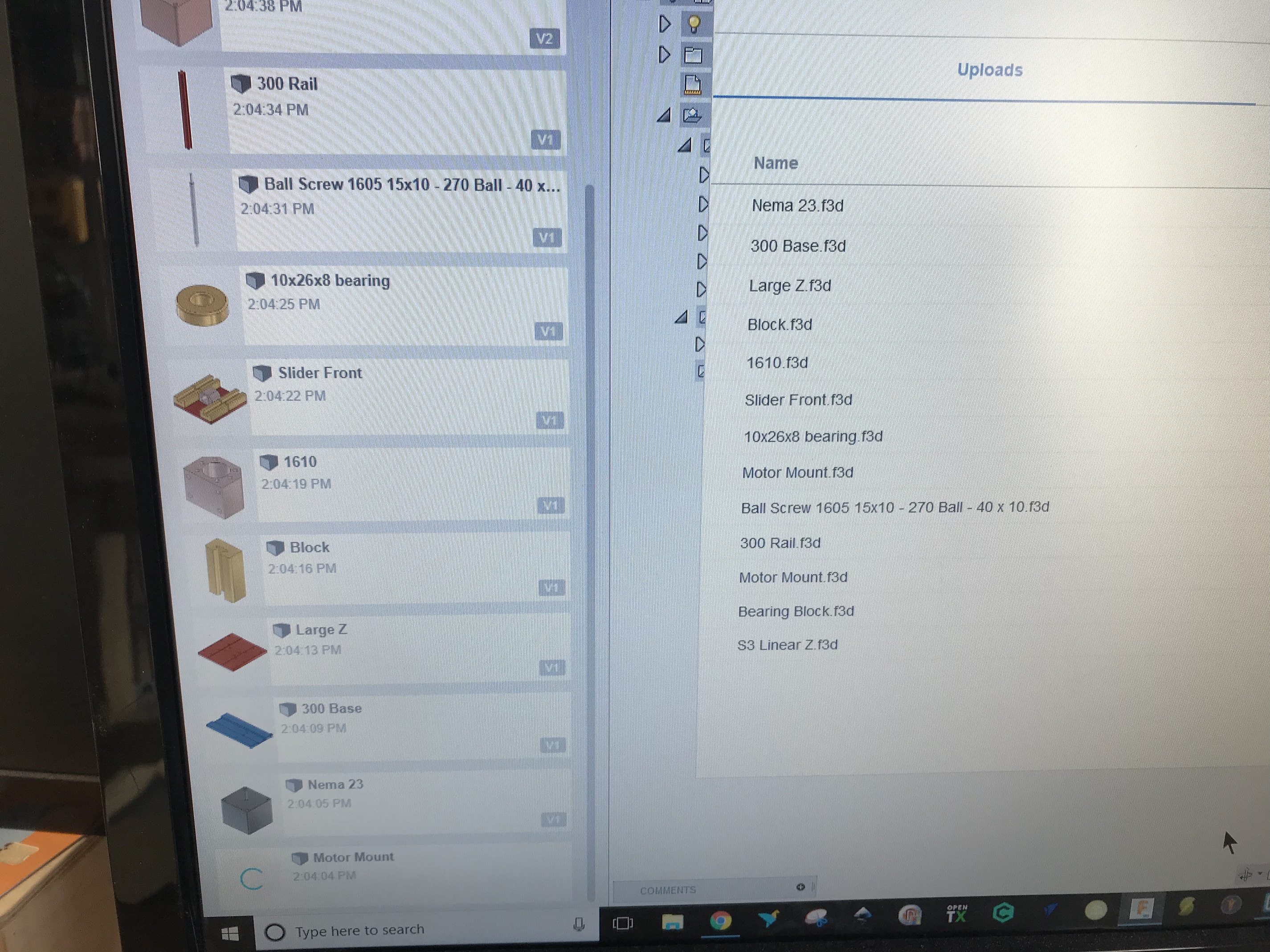
Hmmmm, something funky here. I upload the file you sent above into new folder, watch as the files upload, see one named motor mount with spinning arrow that just disappears eventually. Possibly because there are two files named motor mount?
Sorry to be a pain in the arse!
 ) From there I decided to learn how to use fusion a bit better. To cut a long story short, I have made a revised design of the linear Z axis for the shapeoko and remove the confusion behind all the designs floating in the original topic.