Thanks Griff
I actually laughed out loud at that ![]()
Thanks Griff
I actually laughed out loud at that ![]()
@Luke Thanks for sharing the design! I don’t know that I’ll go down this path, but you’re making it enticing. Are you updating the design on A360? The plate looks like it’s missing some holes. Also, I think the issue with the thin “Motor Mount” plate not appearing might be a naming issue as you have another part named “Motor Mount”. Fusion keeps a version history, and I think the common name is throwing that off.
@Griff Either of you guys made any more progess?
Again, thanks for sharing.
Yep it’s all done in fusion. I didn’t add the vertical holes for the guide rails as I wasn’t sure on the spacing. Whilst @Griff had 30mm from the top and 60mm between I had 25mm from the top and 60mm between. It should be a simple add.
Thanks for the tip on the end stop
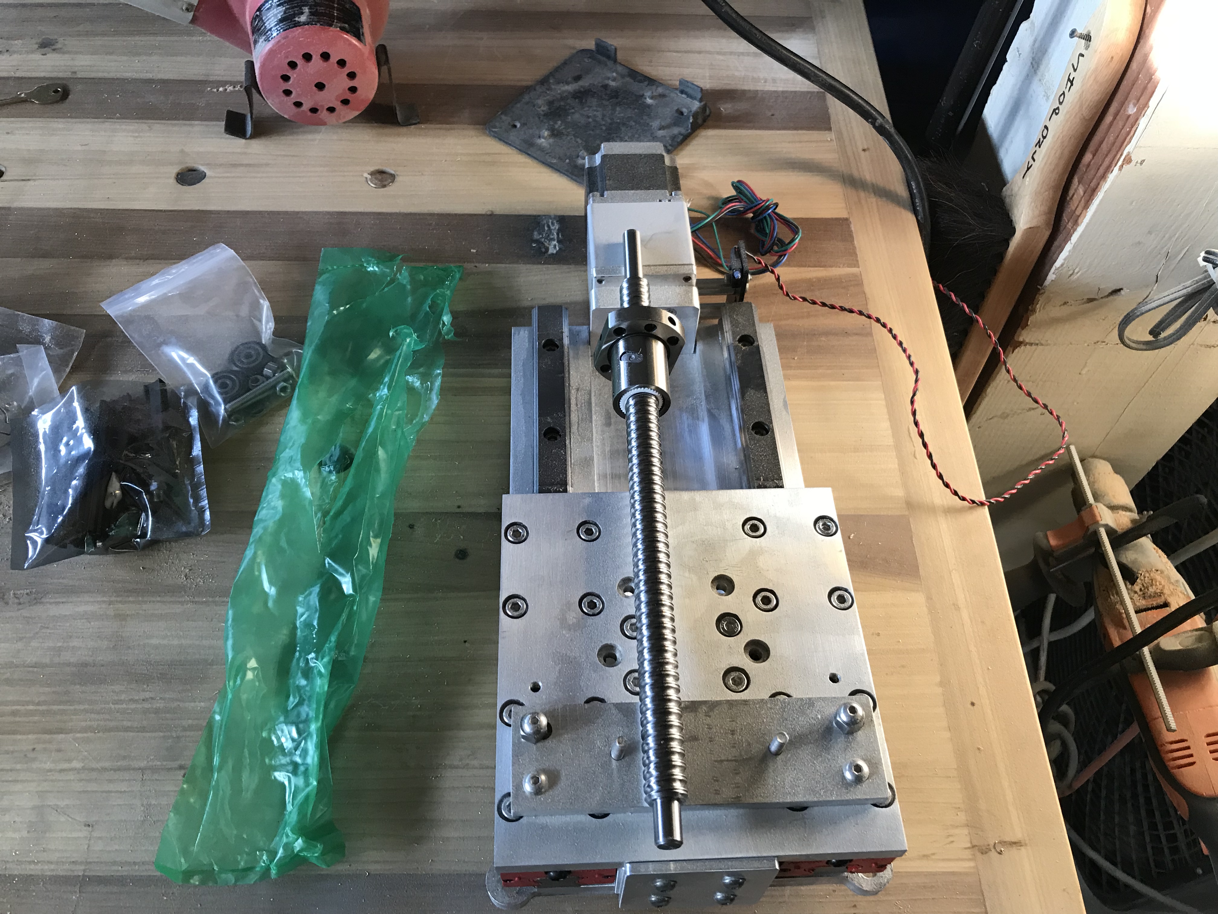
@neilferreri still waiting for my last component, the ball screw. All else is complete.
I added a set of holes to the 611 mount to enable some vertical mount height flexibility.
Really looking forward to installing it and seeing how much of a machinist I am 
Finally!!!
The ball screw delivered. Should have all installed…soon.
I’ve acquired an additional distraction, a Prusa Mk3 3D printer kit.
Although, now that I think about it, is not so much of a distraction…those prints take one hell of a long time!!
Stay tuned…
Yes, they sure do. In my old house I had mine in my “office”, and the stepper motor “whirring” noise just drove me bat $#!+ crazy. Now that I’m doing the CNC router thing at least it’s a more constant sound and the machine time/size of product is more “slowinstantly” gratifying. At work we have a large format printer (meter x meter x 1/2 meter build envelope) and they run prints upwards of 100 hours (and this thing is scary fast). I’ve seen them burn through 3-4 3kg spools on one print, how would you like to wait for that!
Dan
Funny you should mention noise…the Prusa Mk 3 is…very quiet  . Plus, I have it in a box to keep the dust away (it’s in my shop) and to enable ABS and PC prints, which makes it silent, really.
I have an open delta printer (Rostock Max V2) and a closed up Cartesian Makerbot clone. Neither is very loud, actually pretty quiet, but it’s the pitch of the steppers that bugs me. It’s weird, I’ve worked in sheet metal shops for a long time and the sounds of grinders and sanders on metal doesn’t bother me at all (have some midrange hearing loss though). If I’m eating dinner with my kids and someone scrapes a fork on a plate I nearly jump from my skin, it’s similar to the sounds of the 3D printer in my ears, like nails on a chalkboard almost. The ShapeOKO noise doesn’t bother me either unless I have feeds/speeds way off, but I have adopted some hearing protection as of late to save what’s left of my hearing. Anyways, rambling at this point. How is the new Z coming along? I still have my original CNC4Newbies slider sitting on the bench, I may never install it, haha!! The design you and Luke have been working on looks superior to be honest. Very cool stuff!!!
Dan
After some flailing and maybe a curse or three, I’m at the point where I can begin dialing in my new Z.
Thank you Luke, Mr.Beaver for the design.
Congrats, Griff, it looks like all your work has started to pay-off.
Rockin’ and Rollin’ buddy!!! Now get back to making cool stuff so I can live vicariously through your awesome wood projects!
Dan
What software do you use to work .
I’m dabbling with CNCjs and UGS.
Does CNCjs support homing yet?
Awesome work. Time to see the results… How did the tramming bracket work for you?
CNCjs does support probe. In fact, here is a macro @neilferreri kindly provided to me:
This one will probe Z first, so you don’t have to mess with changing distances. You can paste the stuff in parentheses with it as a reminder)
(start with the end mill 15mm ABOVE the plate, about 15mm or less from bottom left corner.)
G21 ;make sure we’re in mm
G91 ;Incremental mode
G38.2 Z-25 F75 ;Probe Z
G10 L20 P1 Z22 ;Set Current Z as 22mm - thickness of your plateG
G0 Z3 ;lift Z 3mm
G0 X-25 ;Move left 25mm
G0 Z-10 ;Move down 10mm, should be 7mm below probe surface
G38.2 X25 F75 ;Probe X to the right 25mm
G10 L20 P1 X-10.175 ;Set current X location as negative half the bit diameter - 7mm thickness
G0 X-10 ;Move left 10mm
G0 Y-25 ;Move forward 25mm
G90 G0 X5 ;Move to X5 (absolute) - will put you 5mm to the right of left edge of stock
G91 ;incremental
G38.2 Y25 F75 ;Probe Y
G10 L20 P1 Y-10.175 ;Set current Y location as negative half the bit diameter - 7mm thickness
G0 Y-10 ;Move Y-10
G0 Z10 ;Move Z up 10mm, should be 3mm above probe plate
G90
G0 X0Y0 ;Go to X0Y0
@neilferreri has also written one for tool length offset, "Automatic" Tool Length Offset
The tram/router alignment design is brilliant. Using machining blocks I was able to level the mount in seconds  . Today I will use the technique you posted to finish up. Then it’s back to doing useful work!
Oh awesome, I didn’t realise it did (I didn’t see the tool pane) I will sure be taking a second look at CNCjs.
I’d love it if if the probing was a feature of the software rather than a macro. I find myself swapping bit sizes all the time. I guess I could have a number of macros for each bit diameter?
I have ran into an issue - I can’t save any macros 
Hit up @neilferreri, he’s the expert here!
No expert…just hacking around.
@Luke What happens when you create a macro?
Also, I believe the developer is working on a probe widget that will allow for an axis other than Z, but I don’t know if it will be a true 3-axis probe.
The really cool thing about the cncjs macros is the ability to use user defined variables. You could do something like below with only one line item to change (NOTE: Untested).
%ENDMILL_DIAMETER = 6.35

(start with the end mill 15mm ABOVE the plate, about 15mm or less from bottom left corner.)
%ENDMILL_RADIUS = ENDMILL_DIAMETER /2
G21	;make sure we’re in mm
G91 ;Incremental mode
G38.2 Z-25 F75	;Probe Z
G10 L20 P1 Z22	;Set Current Z as 22mm - thickness of your plate
G0 Z3 ;lift Z 3mm
G0 X-25	;Move left 25mm
G0 Z-10	;Move down 10mm, should be 7mm below probe surface
G38.2 X25 F75	;Probe X to the right 25mm
G10 L20 P1 X[-7-ENDMILL_RADIUS] ;Set current X location as negative half the bit diameter - 7mm thickness
G0 X-10	;Move left 10mm
G0 Y-25	;Move forward 25mm
G90 G0 X5	;Move to X5 (absolute) - will put you 5mm to the right of left edge of stock
G91 ;incremental
G38.2 Y25 F75	;Probe Y
G10 L20 P1 Y[-7-ENDMILL_RADIUS]	;Set current Y location as negative half the bit diameter - 7mm thickness
G0 Y-10	;Move Y-10
G0 Z10	;Move Z up 10mm, should be 3mm above probe plate
G90
G0 X0Y0	;Go to X0Y0
Quick video showing how to make a macro.
@neilferreri, as a teacher you will appreciate if I say learning has occurred. I am proud to say I have improved my understanding of CNCjs from the level of zero to now being able to set up jobs and easily navigate around the workspace.
I think I deserve a gold star  .
.
Oh, also, your tool change macro works great, thank you.
Thanks for the video, it’s not user error. When I click add it just saves but nothing is saved/added to the macro box