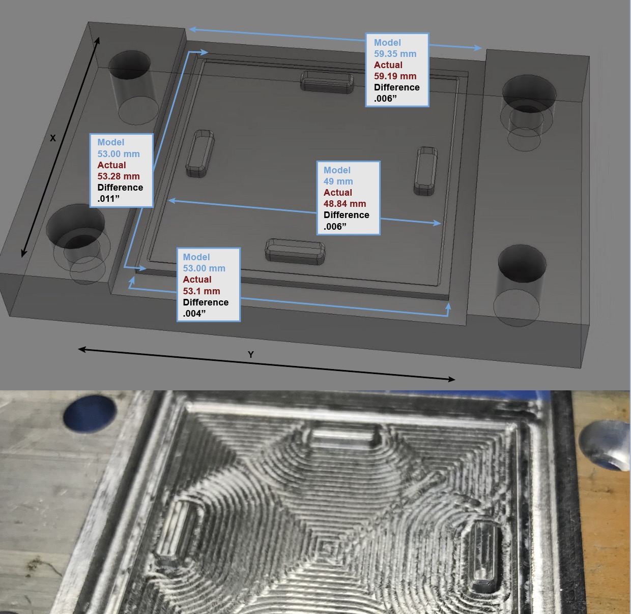
A little disappointed after getting some caliper readings on my latest job.
Is this what I can expect on the Nomad 3 in aluminum?
Any advice into tightening the slop here?
It might be good to check the tool’s true diameter. A tool that is supposed to be 2mm but is in fact 1.95mm will give errors of 0.1mm on that shape.
5 Likes
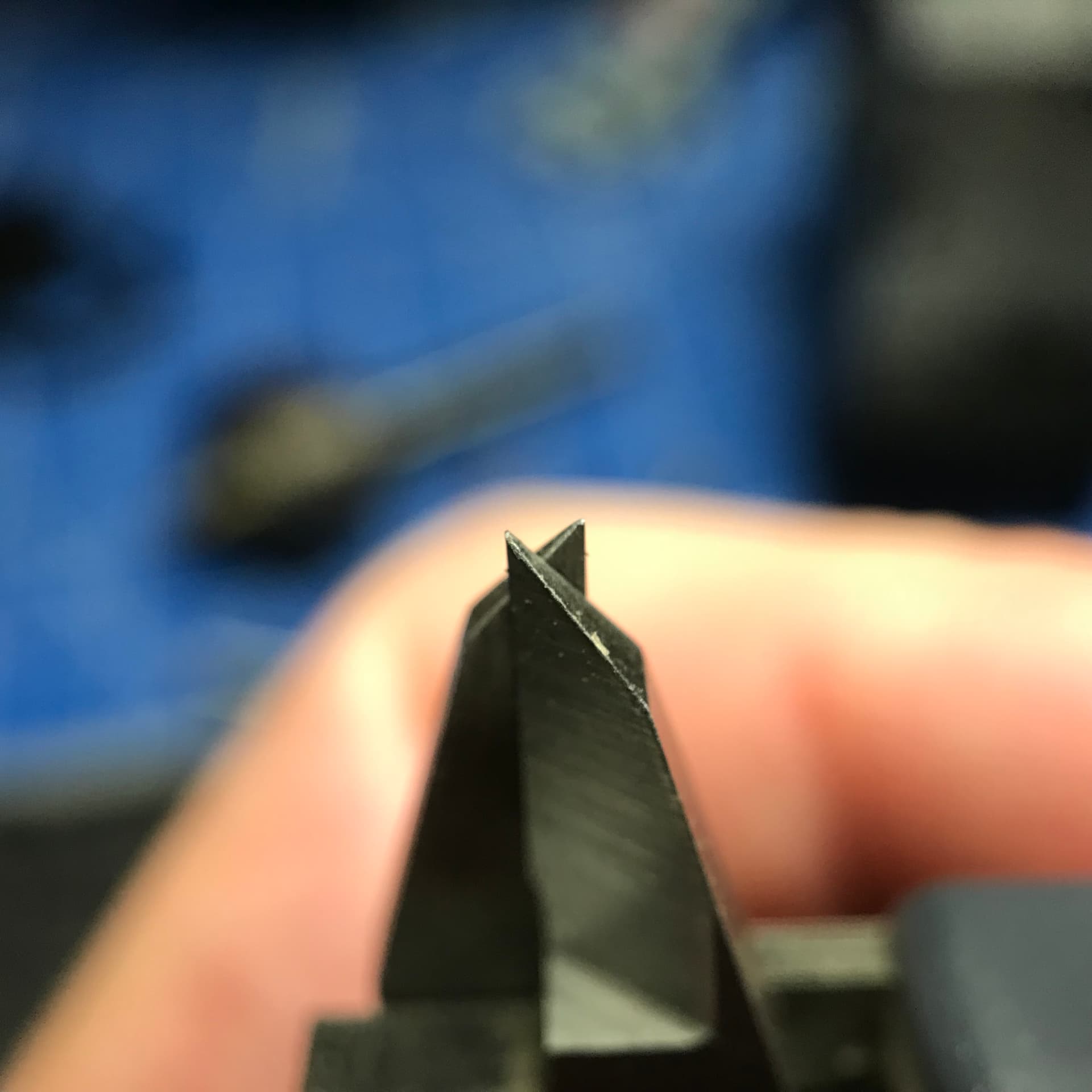
Thanks, that is part of the equation, my 1 flute 1/8" is reading about 2.8mm instead of what I assumed would be 3.175.
I checked the run out and there is none, but I did notice that if I put even slight pressure on the collet that I get about 3 thou in deflection in the spindle bearings… should i be worried about that?
www.dropbox.com/s/ua0gwtccjy6lzxc/IMG_8082.mov?dl=0
As @Moded1952 has discovered, you can’t really measure the diameter of an endmill with calipers - he actually discovered the measurement damages them too.
One way to do it would be to cut a single line as a shallow slot and measure that.
I’m not sure about the deflection or play in the spindle, since I have a Nomad 833, but this thread might be of interest to you if you haven’t seen it yet.
3 Likes
Yeah that was what made me test for bearing deflection… was hoping I’d be lucky and there would be none. Wasn’t sure if static deflection would be the same deviation as a spindle running at speed or if centrifugal forces came to play in the rigidity, guess it’s time for more tests.
I can confirm that it is difficult, if not impossible, to measure an endmill cut width using calipers. A 1/8" single flute #274Z at the widest point of the tip measured 2.8mm with my calipers. I ran a few swipes with it through acrylic using single passes and the resulting cut width is 3.01. That wouldn’t account for run-out, but I had no measurable run-out, with my thousands probe anyway.

I wouldn’t recommend that you try to measure the width of the cut directly (i.e. carve a “valley” and measure the width of the “valley” with for example calipers). Measuring the width of such a small internal feature is really hard to do to the level of accuracy you care about without specialized tools (you certainly can’t get a meaningful reading on a channel that narrow with conventional calipers).
Instead, I’d recommend you machine features that can be measured externally, like square and round pillars. It’s much easier to accurately measure these with a micrometer. Make sure you machine them on all sides and then the width of your endmill is just <nominal diameter> - <actual pillar width> + <expected pillar width>.
4 Likes
But I am trying to measure the width of the cutter itself, are you suggesting that I use the error in the feature against the size programed to determine the width?
I was putting the upper jaws in the channel and getting a consistent 3.01mm from anywhere in the chanel on the x and y, not sure how that is any less accurate that measuring a 3mm wide pillar with the lower jaws
Yes, exactly.
Repeatability != accuracy. The upper jaws on calipers are nigh on useless for the level of accuracy we want here.
The big difference is that the bottom jaws are essentially planes, the top jaws are blades. The bottom jaws naturally align themselves against flat, parallel surfaces, ensuring that you properly measure the distance between them. The top jaws do not. In fact, the thickness of the wedge behind the blades leads them to naturally unalign, throwing off your reading. The blades are also not a constant thickness, they narrow to points, so the maximum depth you can get inside your hole at 3mm is itself around 3mm.
I’m not just speculating and making things up, I’ve learned this through experience. I’ve measured endmill diameters with cuts like yours (horribly inaccurate), with pillars (decent) and with cheap optical sensors (good, with calibration).
Try it and I’ll bet you get a different number.
And don’t get me started on hole diameters… For us hobbyfolk, I think the best option is probably go/no-go gauges.
The pillar doesn’t need to be 3mm. I’d recommend more like 10mm or 20mm to make it easier to handle and get an accurate reading. The size of the pillar itself doesn’t matter so much, only the delta between what you measure and what you expect. You don’t want to go to extremes like 100mm though or you add in error from the Nomad (e.g. imperfections in the lead screws).
2 Likes
In a scenario where I was only trying to find the diameter of the cutting tool I could use the rest of the system to determine the size, but this was the first step into trying to determine the issue of .006 slop overall in my part dimensions. I haven’t eliminated any of the other factors that could be contributing to the issue, like backlash, tool deflection, or a bad spindle.
So how do we isolate the measurement to eliminate it from the equation without an optical comparator… lets pretend it is 1905 in my shop:)
Eliminate those first, then measure the endmill with test cuts.
Fundamentally, there are two ways to measure the diameter of an endmill:
- Optically, not an option without $$$
- Mechanically
- You need a way to turn the endmill with a high degree of concentricity
- You need a way to move something closer to the endmill in high-precision increments, until the endmill touches the thing
Your mill, in theory, has both of these things, in the form of its spindle and linear motion system.
If you have a way of acquiring both things elsewhere, then by all means, do so. Otherwise, you need to validate your mill:
- backlash: Put a DTI on your Z-axis carriage, put the tip against a surface that’s fastened to the machine’s bed, move away 0.1mm, then back 0.05mm. Did the machine actually move 0.05mm?
- tool deflection: When you do your test cuts, make light cuts so there’s not enough force to cause the tool to deflect.
- bad spindle: Measure runout and try pushing on a dowel pin in the spindle to see if there’s slop in the bearings.
Thanks, I’ll get some readings on the backlash. I had checked the runout by hand turning the spindle against a DTI. Run out looked good but bearings… maybe not so much.
also noticed a faint clicking noise as the spindle deflected.
Oh, you’re sure it’s the bearings? That sounds like the loose spindle issue others have seen. Might be worth writing to support.
no, not sure, I had assumed it was the bearings. I will reach out to support.
As Lucas indicates (pun intended), this is going to make measurements hard for you.
The static (low speed) runout on the spindle is not going to be the same as the dynamic (high speed) runout on a spindles this small and fast with wobbly bearings. Any imbalance in the rotating assembly will tend to throw the spindle out radially to the limit of the bearing slack as soon as it spins up, giving you a higher effective runout.
If you then add in the helix of the cutter you’ll get a mathematically elegant curve down the length of the cutter for effective diameter. Machinists would not consider this as elegant or interesting as mathematicians.
2 Likes
Every machine is calibrated before it leaves the shop. That 0.011" off reading looks a little odd, though everything in the X axis looks pretty close. Biggest question to ask is are you running a finish pass? Because if not, that’s probably where the majority of your error is coming from. As you’ve observed, the spindle bearings will allow a small amount of deflection under load despite a bit of preload we put on them, which is why a light final pass will give the best finish and tolerance.
A test cut in a much softer material like HDPE would also be good to verify if it’s a machine calibration issue, or if it’s deflection under dynamic cutting loads.
5 Likes
Thanks Winston
would .003" of deflection with light finger pressure on the collet nut on a static spindle be within calibrated factory preload specs? I’m happy to keep testing but want to eliminate this first, as the machine only has a couple of hours run time on it with very conservative feeds. There is a slight clunk and then that jump of deflection, not a steady deflection from pressure… also I noticed the deflection seems the greatest on the X when pushing towards the left side of the machine… so if the belt was pulling it .003 to the right of the X and I pushed it left I’d get double the reading. Just noting because my errors seem the greatest in the X
I don’t know your exact test scenario, but unless you’ve managed to lock down the entire X-axis, that test of pushing on the spindle nose isn’t going to tell you much about the runout/stability. It could be the spindle bearings yielding, it could be the actual lead nuts/anti-backlash system deflecting. But 0.003" with pressure isn’t a huge red flag, and waaay smaller than what could be causing the 0.011" deviation observed. To confirm, are you running a finishing pass in your gcode?
I was not on that outside diameter pass mainly because that outside groove was the width of the cutter and I was repeating the same pass with multiple doc’s… i figured it would act as a spring pass
How much would you recommend to leave behind for a finish pass in MIC 6 with the single flute #274Z? Oh and while I have your attention… are the side windows on the N3 pollycarbonate or acrylic, my laser wants to know:)