If your step downs are evenly spaced, the cutting force on each pass will be the same, and each pass will see the same deflection. Technically it will be even worse as tiny amounts of wall contact/friction from areas above the active cutting stepdown will try to push the cutter off the walls. That’s why on very deep cuts you may observe a fraction of degree of taper on the walls. But this is really only a factor for like… stock an inch thick.
But bottom line: Unless you run a pass that’s not cutting into additional material in the vertical axis, no that does not count as a spring pass.
I would leave about 0.006" on the floor to clean up, and about 0.008"-0.01" on the side walls. Sometimes I use a little less if my roughing toolpath is more conservative. You basically want to ensure the stock left is greater than any potential deflection. so given what you’re measuring, 0.01" in the horizontal directions would seem appropriate. Z axis is usually pretty good.
Side windows are acrylic. Polycarbonate might technically be more durable, but the spindle isn’t strong enough to require anything “bulletproof” for safety. Also, acrylic is more scratch resistant.
OK I will stet up some tests cut to nail it down, appreciate the help. Are there some g-code calibration files already in existence that I’m overlooking?
Good to know, Acrylic is has better clarity and I figure that was what it was, but I couldn’t find the answer for sure so I made a new window in acrylic to be safe, now I can mod the other one if I need to
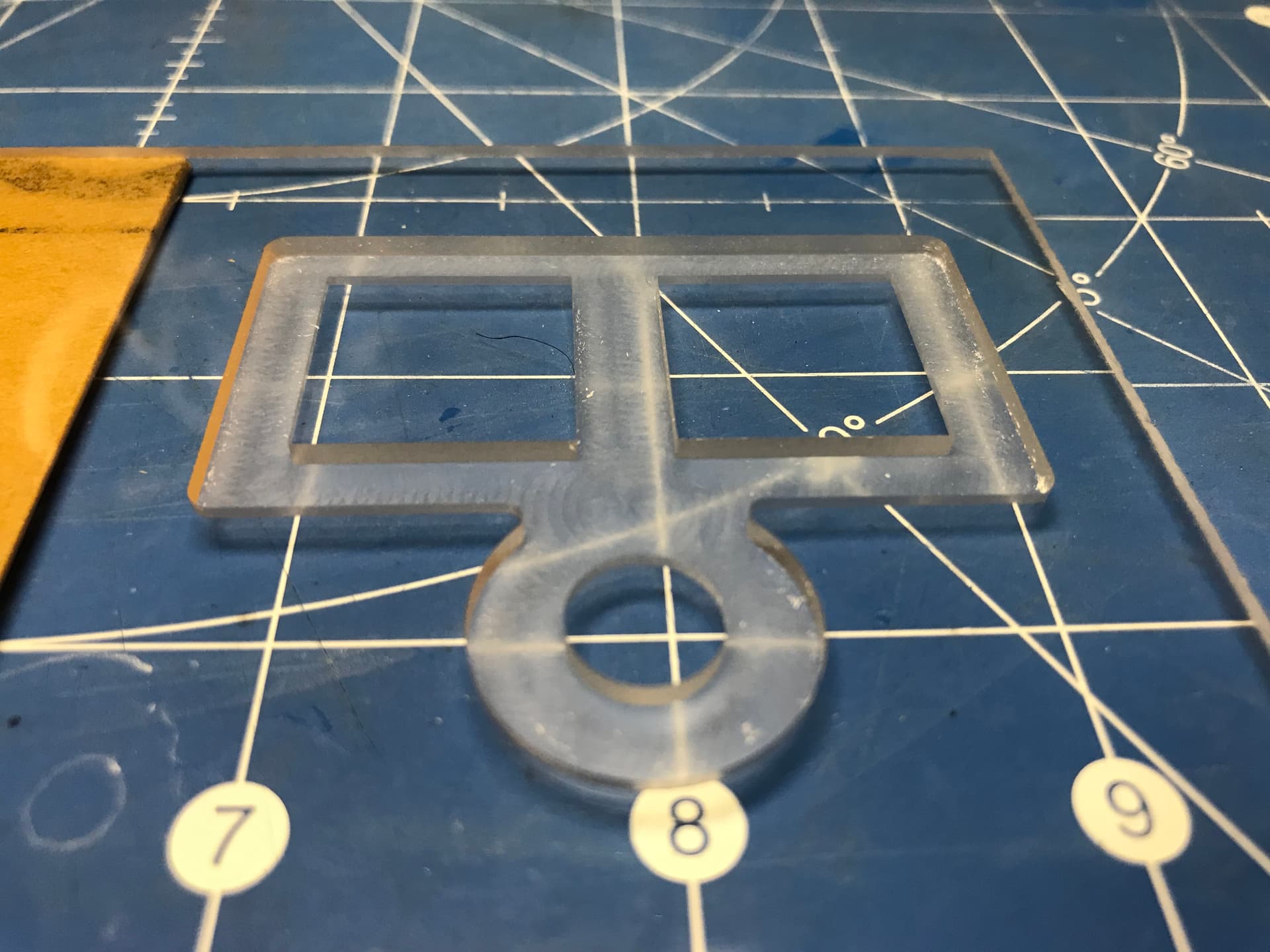
OK so I ran a calibrating test in acrylic with two 20mm squares and one 10mm circle.
Spindle at 20000 RPM
DOC .5mm
Adaptive roughing at 44 in/min for a chip-load of about .02” on a single flute 1/8” end mill
Finish pass of .008 on the sides at half that chip-load.
I estimated the bit width to be 3mm instead of 3.175 based on my “rough” measurements
The resulting squares are 20.01 mm on all sides and the circle is about 9.94 mm
…so for acrylic anyway we are within a .002” tolerance.
The next step is to design a test for aluminum and see if that triggers any major deviation in the spindle under load, but it was nice to have these results.
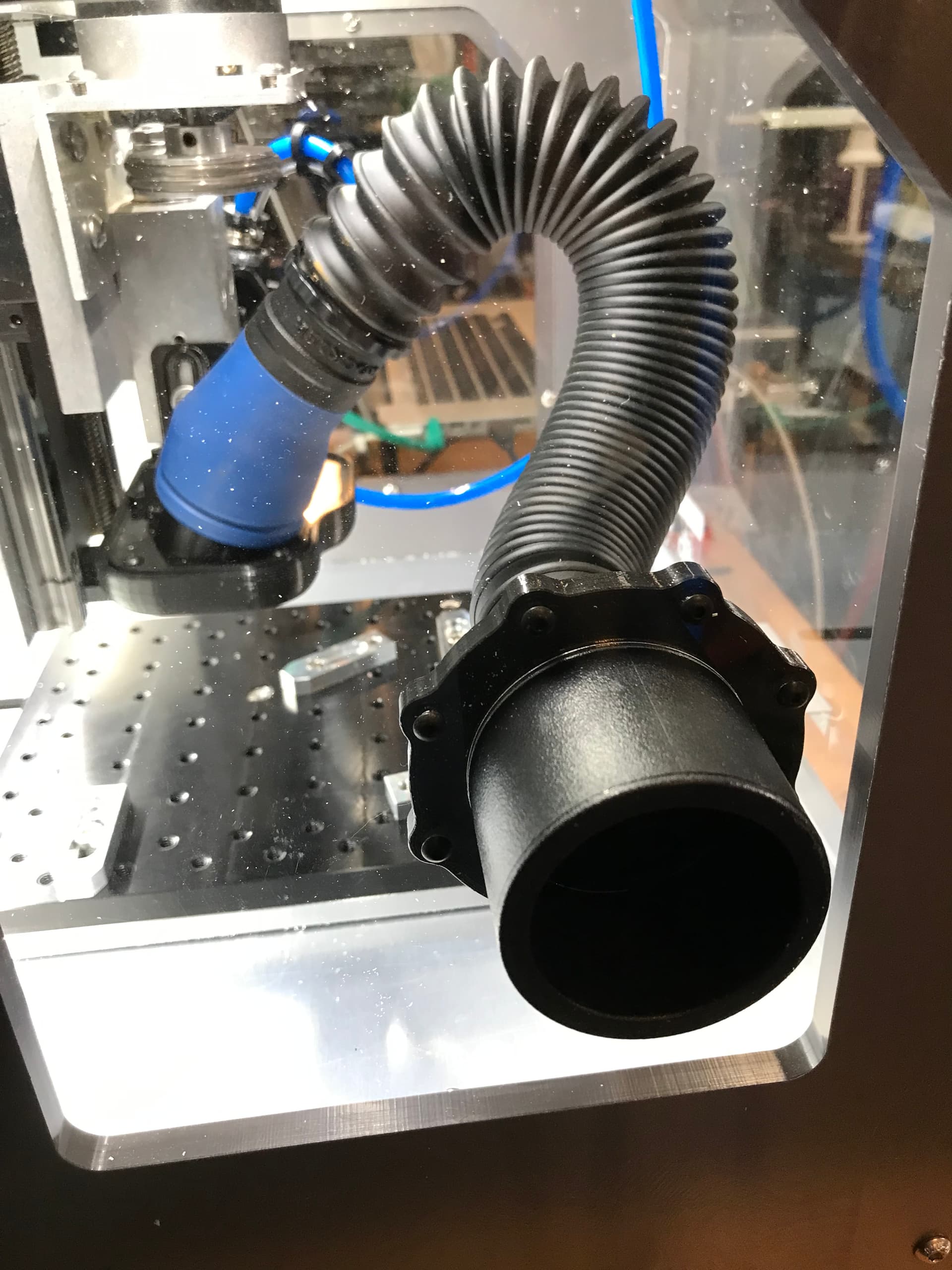
I am also happy to report that the combination of an air needle for pinpointing chip removal and the vacuum boot with the brush works amazing. Cutting acrylic is usually a static cling mess and there were absolutely no chips afterwords. Nmd3Nodust.MOV
That’s after you told CAM the 3.175mm endmill is 3mm?
For me, that’s setting off alarm bells.
If the 274-Z on a Nomad really is making 3mm cuts, I’d talk to support. A couple thou out is one thing but 0.175mm wayyy too much. Something is wrong. Either:
Carbide 3D sent you a defective endmill
They sent you a defective machine
You somehow damaged the endmill such that it makes 3mm cuts (unlikely)
That is indeed the case. I can change it to 3.175 in fusion and re-run the job to see what happens. It may be that I was compensating for run-out instead of actual tool size… but how would I know for sure?
As we all know, it was invented in 1986 by Montgomery Scott in order to transport tanks of water sufficient to hold whales … to the future so they could tell an alien ship that all was well.
At this point, I think the important thing is to talk to support. 0.175mm of error on a Nomad, in plastic is not okay.
That said, if I were to try to handle it myself without support, my ideas are:
If you’re okay hooking up a 24V power supply to something, buy an optical sensor like this and hold it on your machine (e.g. in a vise) and move the endmill towards it to get the diameter optically. This is the method I used in another thread. The sensor costs about $20 and had repeatability of ~2um as far as I could tell. I didn’t quite figure out how to calibrate it though.
Otherwise, buy an endmill that actually has specifications. PreciseBits has some suitable plastic endmills and their diameters are specified to +/- 5 tenths accuracy. Harvey Tool has them at around 2 thou but you need to be careful - the 1/8" endmills are less accurate.
On that last point by the way, if you’re after accuracy, you usually want to avoid endmills with a cutting diameter that matches the shank diameter. One of the guys from PreciseBits elaborated on that a bit here.
Anyhow, those are ways to get an endmill with a known diameter. If you still get weird results, it’s probably not the endmill.
If you’re measuring cut width as a proxy for endmill diameter, make sure you run a spring pass. Not only does plastic have a small degree of elastic deformation where the cut channel closes behind the cutter as it passes, but a single flute endmill can be bounced back and forth between the walls by a certain degree of bearing and cutter deflection. It’s only making contact with one side of the cut channel at a time, vs a 2 flute that has more balanced cutting forces and cannot possibly form a cut less than the distance between two cutting edges.
OK one more test, this time with the supplied 1/8" 2 flute endmill with a finish and spring pass using your settings from Cast Acrylic Machining Guide for the Nomad CNC and a 3.175 tool measurement. Should be enough data to confirm calibration I hope.
Have you tried a circle square diamond test in different materials? Might be interesting to see back to back with and without your dust collection hooked up.
I googled it, so I now know what it looks like but I know nothing of the test. Are there exact parameters it needs to follow to be a valid test? Clearly I’m no machinist as it seems this test has been used for decades to test for accuracy.
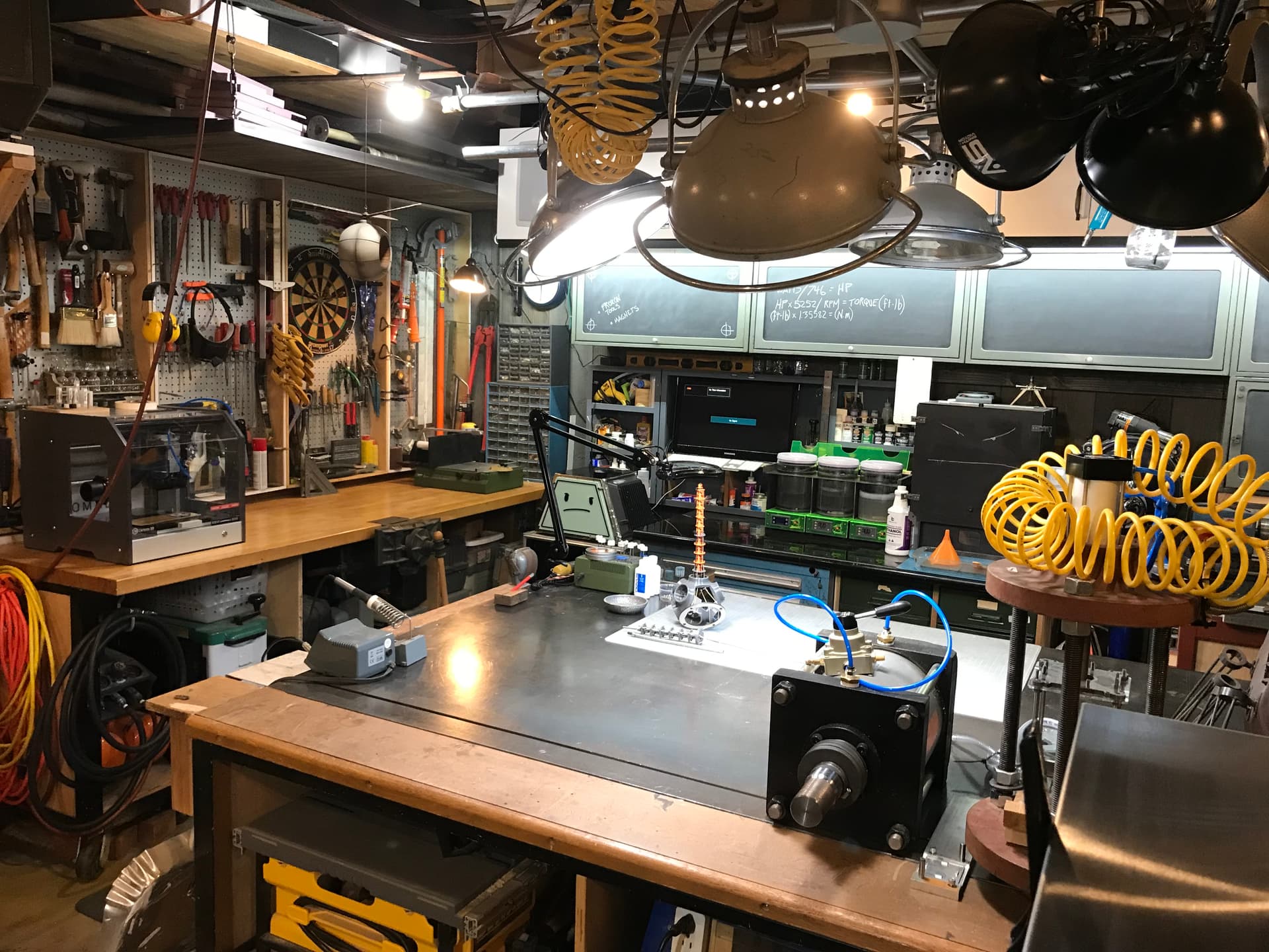
That is a big ass air cylinder what is it for some sort of press? I used to install 3" and 4" air cylinders in cars in place of coil over struts for adjustable air suspension. 150 psi through a 1/2 value to each corner and you could launch a honda civic over a foot vertically in one shot from completely laid out.
You can use any dimensions for the circle diamond square test to fit to your machine and material and measuring gear — just cut the part and then measure and compare the actual measurement/angles to the ideal, then based on that you can adjust for endmill diameter, backlash, &c.
Wicked surplus! 8" bore, about 5000 pounds of force. It was for the top platen of a molding press that I’m building but it might end up in a press for die cutting foam sheet pieces… or a manual injection molding machine. It was more than I needed but I got it for a couple hundred bucks so there is more I can do with it.
Ah ok, I was looking at a more elaborate test with a scalloped diamond stacked on a square then circle bored thru… so I’m just missing the diamond on the test I ran.
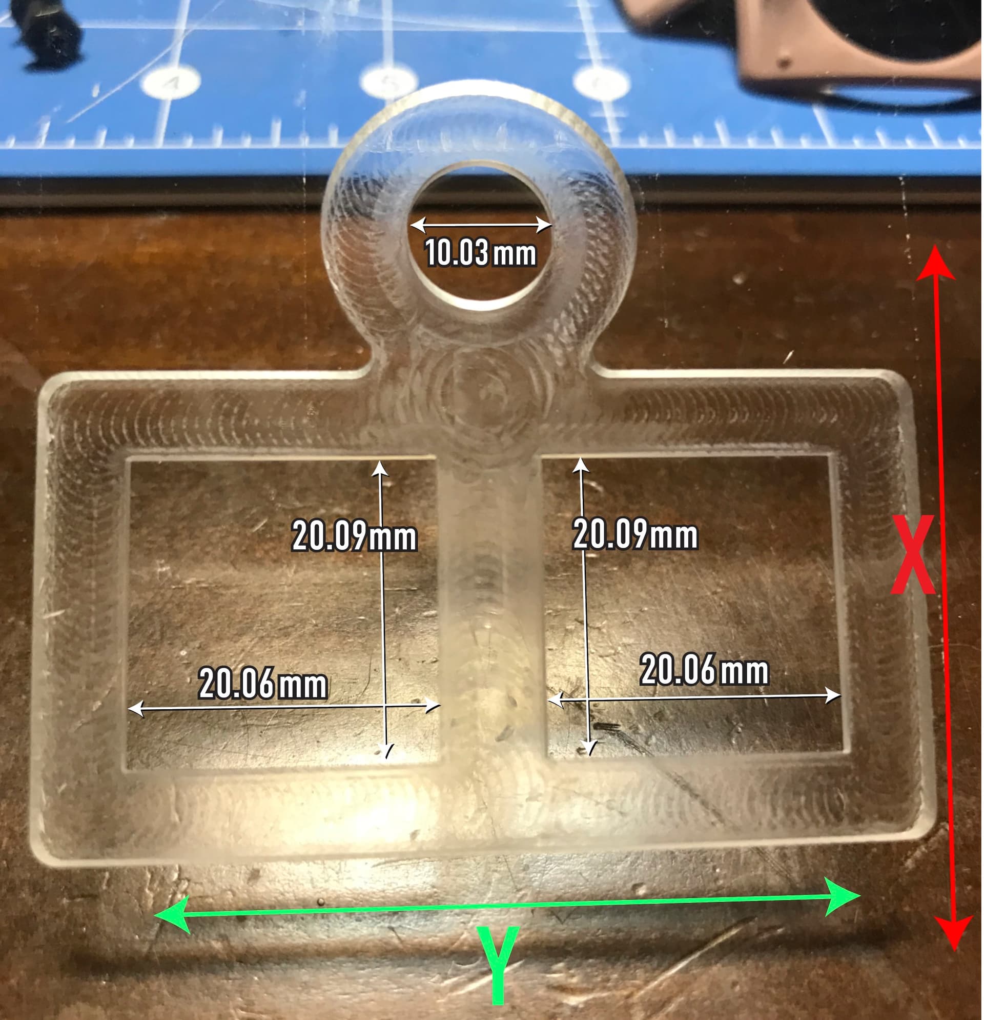
1/8" 2 flute endmill with a finish pass of .008" and a spring pass
Spindle 10000
DOC .5 mm
Travel 44 in/min roughing / 26 in/min finish
So the X is about 3.5 thou off and Y is a little over 2 thou
But this is going to be a best case scenario using acrylic and I was looking for accuracy in aluminum.
Is this within spec for the Nomad 3?
Now that you’re getting down into the tens of micrometers, it might be worth cutting the shapes out fully so that you can measure them a bit more accurately still.
I’d try incrementing your endmill diameter in CAM by another 0.06mm and repeating the cut. If you do that, you should be be able to get dead on on Y and 0.03mm off on X (so about 1thou).
Weird that the circle has different measurements to the two squares though.
The Nomad 3 doesn’t have a spec. The 883 Pro though was specified for 1.5 thou repeatability and 5 thou/ft accuracy so you’re just about there now I think.
As the circle is smaller than the squares, does this suggest a per-tooth distance error which is increasing broadly linearly with distance? If so it suggests over-tight belts, or incorrect steps per unit distance setting in GRBL $$ setup