How are the Nomad Y axes built? I’ve not seen how a Nomad is put together but the Y plates frequently seem to end up being the weak point on machines where flex creeps in. As the Nomad does Y travel on the table you at least have a fixed gantry to stabilise.
The linear motion configuration is very similar to the X-axis: 20mm steel rods with linear bushings embedded in a hefty chunk of Aluminium that has a lead screw going through the middle. The steel rods are embedded in the Aluminium plates at the front and back of the machine. The front and back are also connected to each other with what seem to be the beefiest structural components of the Nomad: 50mm x 25mm x 430mm Aluminium bars. These bars run down the side of the machine.
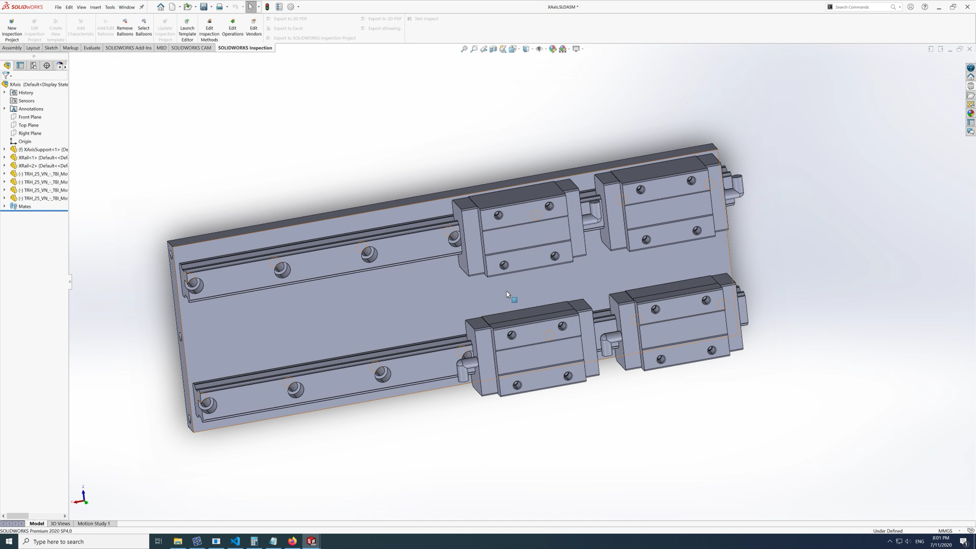
Speaking of the mock by the way, here’s what that plate looks like with the 25mm rails and their carriages attached to it, it’s a tad cramped, the carriage would have to be around 180mm wide and I don’t have anywhere to put the ballscrew with this size:
Then yes, 0.12mm seems like a reasonable deflection for that small piece of armour plating
Aha, in conjunction with some pics from the Carbide getting started guide for the Nomad, that’s pretty chunky.
If it was me, I’d be getting my dial gauge out and measuring deflection between various parts for consistent applied forces to understand what deflects notably and what is not a problem. It’s much easier if you only fix things that are actually ‘broken’.
To nobody’s surprise, I think Vince’s list of upgrades is a good place to start. I know those leadscrews can be sloppy, even with spring loaded nuts. I personally am not a fan of those round rod linear bearings, they allow too many degrees of freedom for my liking and pairs of them work as cantilevers when forces are applied. They just don’t have the inherent stiffness of a beam. That being said, they’re pretty short on the Nomad and if you measure up the wall thickness (rods or tubes?) you can easily calculate the deflections and I suspect they are quite small.
I’d be interested to see how much side to side flex of the gantry is allowed by those vertical plates. The backplate for the X beam should stop the worst of the flex there but they still might deflect notably.
I’d also be interested to see whether the base of the machine is rigidly square or whether it flexes into a trapezoid when viewed from below. Bolting the front and rear members to a flat plate would address that if it is present.
I did a quick check and put a DTI in the vice and put the tip on the Z-axis carriage and pushed various parts of the machine as hard as I could comfortably push with one hand (scientific, I know):
Measuring X deflection:
Push on Z-axis carriage: 0.15mm deflection
Push on bed: 0.1mm deflection
Measuring Y deflection:
Push on Z-axis carriage: 0.05mm deflection
Push on spindle tip: 0.03mm deflection
Push on bed: 0.05mm deflection
So the Y-axis is okay but the X-axis is pretty wobbly.
I’ll try probing some other parts of the machine tomorrow.
I used a combination of a 5kg weight on a string with a pulley and a cheap digital luggage scale from Amazon for repeatable 5kg pulls on the Shapeoko. But my machine doesn’t have side walls…
That’s correct, but don’t forget that that plot is in the non-rotating workpiece coordinate system. The endmill will obviously still “see” forces that change direction all the time in its own (rotating) reference frame. You can switch between coordinate systems from the context menu (right-click).
Sort of, but here you assumed fixed boundary conditions left-and-right, while there are in fact somewhat flexible columns there… Anyway, I agree that a backing plate like this in itself will not contribute much to the flexibility of the machine. For a chain of serially connected stiffnesses k_i, the total stiffness k is given by
which means that the weakest link in the chain (smallest k_i) dominates the behaviour of the whole.
In other words, going for @Vince.Fab “low-hanging fruit” first can be very effective.
The ARC 15MS carriages are only 41 mm long. That may give you some of your travel back. At 34 mm width, it should be possible to fit two rails and a 1204 ballscrew on 130 mm width.
If you go for a 4-carriage layout, I don’t think you need to be too concerned with load ratings. Single-rail - that’s different. Also, I have seen cheap knock-off linear rail carriages that came delivered with play. That is a problem because play is usually adjusted by choosing the ball size; not something you can fix yourself.
Would there be any value in showing them both in the same plot? Would it be helpful to minimize the variation in force in both reference frames?
Yeah, I think I’m going to take @LiamN’s advice and try to figure out where the flexibility is. I should also probably do it with the steppers actually turned on…
Interesting, looks like they’re selling these. The catalog page there though puts them at 46.5mm though, including the oil nozzle.
Speaking of those oil nozzles, does anyone know if it’s possible to remove them when not in use?
I think the main here factor is going to be the width of the Z-axis carriage though. If I get say this spindle holder, the Z-axis carriage is going to be at least 120mm wide anyway, so as long as the blocks are less than 60mm long, no travel is lost. In that case, I could go up to the 20mm rails.
I was also reading this guy though and he made a good point: the surface that you mount the rails to has to be more rigid than the rails themselves, otherwise the rails end up bending the mounting surface instead of the mounting surface bending the rails flat.
So 15mm rails seem to be the right choice here. Overly beefy steel rails are just going to bend my Aluminium plates and I want accuracy more than an insane load rating.
Thanks, that’s helpful information. I was looking at the numbers and seeing ratings in the kN but I have this bias against buying the smallest of anything.
Related question: if a linear rail is rated at 7.7kN, is it really possible to hang a 700kg weight from it?
I saw that that was a possibility in the datasheets but I was going to go for preloaded rails with say 4/µm of play. If I order them like that they should come like that, right?
Okay, I did a bunch more measurements, this time the stepper motors were turned on:
Measure 6mm rod in spindle, deflection parallel to Y:
Pull 6mm rod in spindle: 0.2mm
Rotate Z-axis carriage: 0.1mm
Push Z-axis carriage: 0.05mm
Push X-axis carriage: 0.07mm
Push bed: 0.1mm
Push vertical supports: 0.04mm
Measure 6mm rod in spindle, deflection parallel to X:
Pull 6mm rod in spindle: 0.2mm
Rotate Z-axis carriage: 0.05mm
Push Z-axis carriage: 0.1mm
Push X-axis carriage: 0.1mm
Push bed: 0.07mm
Push vertical supports: 0.05mm
Lower steel rod on X gantry, deflection parallel to Y:
Pull 6mm rod in spindle parallel to Y: 0.03mm
Pull 6mm rod in spindle parallel to X: 0.01mm
Rotate Z-axis carriage around X: 0.01mm
Rotate Z-axis carriage around Y: 0.03mm
Lower steel rod on X gantry, deflection parallel to Z:
Pull 6mm rod in spindle parallel to Y: 0
Pull 6mm rod in spindle parallel to X: 0
Rotate Z-axis carriage around X: 0
Rotate Z-axis carriage around Y: 0
Left vertical support, height around lower X steel rod, deflection parallel to Y:
Pull 6mm rod in spindle parallel to Y: 0.01mm
Pull 6mm rod in spindle parallel to X: 0.02mm
Rotate Z-axis carriage around X: 0
Rotate Z-axis carriage around Y: 0
Push X-axis carriage: 0.02mm
Left vertical support, height around lower X steel rod, deflection parallel to X:
Pull 6mm rod in spindle parallel to Y: 0.0
Pull 6mm rod in spindle parallel to X: 0.03mm
Rotate Z-axis carriage around X: 0
Rotate Z-axis carriage around Y: 0
Push X-axis carriage: 0.04mm
So for me the conclusion is:
Structural elements: Rigid enough. The steel rods and structural Aluminium elements deflect ~30µm, which I think is fine?
ACME screws: Force applied on the carriages, parallel to the guide rails results in ~100µm of deflection at the spindle, so there’s more evidence in favour of @Vince.Fab’s ballscrew recommendation.
Steel rods: The rods themselves are quite rigid and deflect very little but pushing perpendicular to the carriages still results in ~70µm of deflection, which is close to the amount that seems to result from the ACME screws.
So ballscrews seem to be the lowest-hanging fruit but it looks to me like linear rails should also be quite an effective upgrade. With those two upgrades, the deflection should be largely limited to the frame, which already seems quite good.
With original HIWIN carriages, the nipples can be screwed out and replaced by a screw. You can then carefully drill through the plastic holes at the sides of the carriages (2 mm drill) to open a port that is accessible laterally.
Yes, if that is the static rating, they won’t fail instantly - but probably not last very long. Note that the load rating for bearings concerns failure and service life, not stiffness. Stiffness of rolling bearings is a function of preload, number and size of balls in contact.
Preload implies zero play (maybe that datasheet was giving a range). The level of preload is usually specified as a fraction of load rating C, so 0.05 (medium) preload with C = 10kN means the balls press into the races with 500 N (because they are ever so slightly larger than the space between the races) when no external load is applied.
Regarding the measurements, it may be not so easy to repeatedly apply exactly the same force by hand (unless some other means were used?) so I would probably not make a decision based on a 30% difference, but the broad trends seem to support what you suggest. The is one thing to remember when pushing against the drive (screw) is that you may be loading the stepper. At least that is the case with ballscrews: Push the nut and the screw turns, so your force is counteracted by the servo/stepper holding torque, and a stepper doesn’t produce a holding torque unless you force it out of position - like a spring. With ACME screws I’m not so sure, they may be self-locking for small pitch angles under static loading.
Ah, you’re right! I was misreading the datasheet. For some reason I thought Z0 meant no clearance but apparently it means no preload.
It’s definitely not a repeatable amount of force but the thing I’ve noticed is that the deflection in the Nomad isn’t anywhere close to linear. If you were to plot force vs. deflection you’d get a curve with a very very steep section where very little force results in a lot of deflection but then you’d hit a plateau where it’s hard to move the machine at all.
What I’m trying to measure with my very unscientific method is where that plateau starts for various parts of the machine. I want to find the parts responsible for the jelly-like segment of the force/deflection curve and replace them.
True and a good point but it takes a good amount of force to reach that point. With the steppers off (and so providing no torque), I can apply a decent amount of force to the carriages before the carriage is able to move. I’m guessing that’s due to the braking effect of the lead screw.
Hmm, can you elaborate? I thought steppers did have holding torque, at least that’s how they’re specified.
There are aspects of that on the Shapeoko too, what you’re probably measuring is a staged series of backlash & slack then turning to deflection in the structure (it’s different on the Shapeoko but that’s for another time).
The backlash and slack are the slop in the leadscrews, bearings for the ends of the leadscrews, any slack in the linear bearings etc. These will all move initially for not much force and are probably where a lot of that rattling vibration comes from when the machine chatters in a cut.
After that you’ve used up the slack and the leadscrews etc. have turned into rigid members and now you’re deflecting the frame with force, this will be closer to linear.
Like any non-servo motor a Stepper has magnetic fields that repel and attract, the no load position is like the bottom of a valley where there’s no net force in either direction and that’s where your coils and magnets are attracted to. As you try to rotate the rotor away from that position you’re moving ‘up the hill’ of the magnetic field where the rotor is maximally repulsed by the coils, this is max or ‘holding’ torque. If you go too far you get over the hill into the next valley and this is a missed step.
If your steppers are also 200 steps per rev like the Shapeoko then that’s 1.8 degrees per step so 0.9 degrees to max torque, multiply that by the pitch of the leadscrew (mm per rev), let’s say 4mm (that’s a guess), would give you 0.01mm to holding torque and chunking over to the next step.
If you go servo then, so long as your encoder has many more steps per rev then the controller can start varying coil currents to try to create torque to resist displacement. This is all still very dependent upon the underlying physics of the motor though and is my no means a magic wand cure.
Like spargeltarzan says, a consistent force is quite important here. Measuring my Shapeoko I used a luggage scale and went 1kg, 2kg, 3kg, 5kg force on the spindle in four compass directions whilst measuring deflections, this identified whether things were linear and also what measurements were repeatable.
Things like taking out the backlash in one direction before measuring in that direction make a big difference measuring at these scales.
Also, being very consistent and clear about the deflection between which two parts is key. Measuring between the Y travelling build plate and the spindle tells you about the achieved cutter to workpiece deflection but not necessarily where the components that make it up come from.
Don’t tempt me… The main thing keeping me away from them is the size. Even the smaller ones are nearly 100mm long, which I don’t think I can accommodate.
Generally I agree but in this case I’m not really looking for an accurate quantitative measurement (how wobbly the parts are) but more a qualitative one (are the parts wobbly).
I’d try the luggage scale idea again (I did it earlier) but it’s quite difficult to measure most of these parts using it in my environment.
I’d love to mount the DTI to various other surfaces but I’m not sure how to mount it to anything other than the bed (where I can use a vise) and a rod sticking out of the spindle (which has an unfortunate habit of rotating, making it not very useful).
Given that constraint, I’ve been trying to isolate different parts of the machine by applying force to different parts of the machine. For example if I have the DTI mounted to the bed with the tip on the spindle and push on the spindle tip, that will include the deflection from the spindle, the Z-axis bearings, the X-axis bearings, the steel rod, the vertical supports and the bed itself. However if I push on the steel rod, that should eliminate the effects from everything preceding it.
I know it’s not perfect, especially for a good quantitative measurement but I think it’s enough for me right now. Do you disagree?
I’m not sure they’ll be any better on this machine even if they do fit.
Ah,
I found places to clamp the base of my dial indicator to such as the X beam or Y plate and then measure deflection between parts such as X beam to Z carriage, Y plates to baseboard etc.
If you remove some of the covers from the Nomad you should be able to mount to those big base rails, the Y plates etc. to start isolating what flexes where.
All those measurements were done with the force applied in a consistent place, the cutter in the spindle, as that was the most representative of cutting forces applied to the machine.
This sounds very plausible to me. Because the actuators look like integrated stepper+leadscrews, there is little chance getting at the axial bearing. So then, the key modifications (low hanging fruit…) would not so much concern increasing the stiffness of the contraption but rather to eliminate backlash - decent ballscrews can do that. I wonder whether the leadscrews are the only source, though.
(Now, how to account for backlash in millalyzer… )
Stepper was Nomad. Pretty easy to disassemble the thing.My ballscrews are actually solid coupled to leadscrew nubs.
AB nuts are only good until a certain limit, then they just bounce around.
Nema17s will provide enough force for this size machine. I understand going all the way…but just like feeds and speeds, there’s a certain sweetspot where this machine will accel.